Because I already made a game for my midterm project, I wanted to make my final project more of an artistic immersive experience. Specifically, I wanted to build off of the musical instrument that we made recently for one of our assignments. Instead of an instrument, however, this will be more focused on being a soundscape, with dynamic visualizations. However, instead of musical notes, I want to use sounds. The user will generate sounds based on physical input. Essentially, I want the user to be able to switch between two soundscapes – day and night – which will be based on the light of the room. And then by using force sensors and/or pressing buttons, the user will be able to generate sound.
hardware:
a light sensor, force sensor, buttons
p5.js code:
I hope to use the p5.js that produces visualizers similar to this and this, except based on user input from the Arduino.
arduino code:
The Arduino IDE will collect the data from the sensors, i.e. how much light in the room to define the colours, and the force sensors/buttons mapping to the sound being produced.
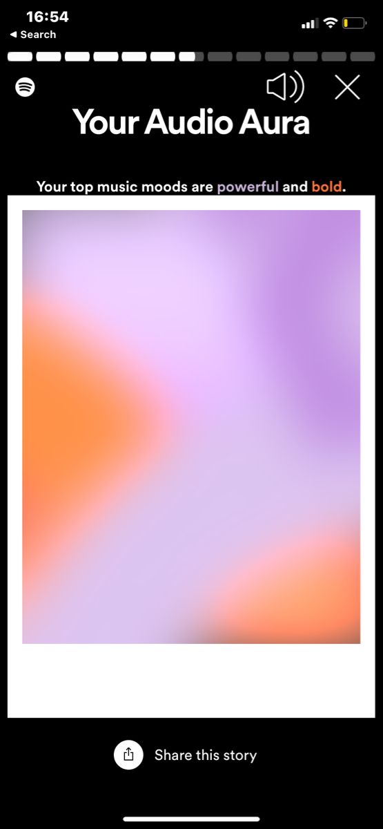
As I was thinking about my idea (and as Spotify Wrapped came out), I remembered last year’s Spotify’s Wrapped element where the application generated a gradient based on the top music moods. Here is an image of what I am referring to:
Therefore, I decided to stick to the colors but to change the purpose and the idea of the game. Instead of making it a game, I want my project to be a personalized experience for the user. The users will be prompted to input colors that represent different emotions to them, such as happiness, sadness, anger, etc. The input will happen with the help of 3 potentiometers, where each potentiometer will represent Red, Green and Blue. After the input is done, a personal color or a gradient will be generated, that perhaps with a click of a button can be downloaded and then sent to the user’s personal device.
Arduino Program:
Arduino setup:
3 potentiometers (I saw we have bigger potentiometers in the IM Lab, perhaps I could use those)
buttons (for progressing through the game and the download of the result)
Arduino Program:
The Arduino program will receive the values from the potentiometers and map them to the color range from 0 to 255. It will also receive the input from the buttons and send them to P5js.
P5 Program:
P5 will be responsible for displaying the correct screens and stages of the experience (such as in the midterm project). It will also be responsible for providing real-time feedback on the color being generated by receiving the values from potentiometers and Arduino. P5 will store the input colors and use them to generate the final result.
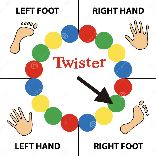
Board games have always captured my interest, and for my final project, I’ve decided to reimagine the classic multiplayer game, Twister, by transforming it into an engaging solo experience. In this adapted version, I aim to introduce interactive elements, to enhance the traditional Twister setup.
Game Components:
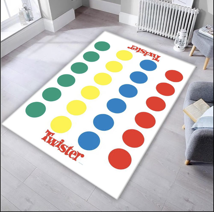
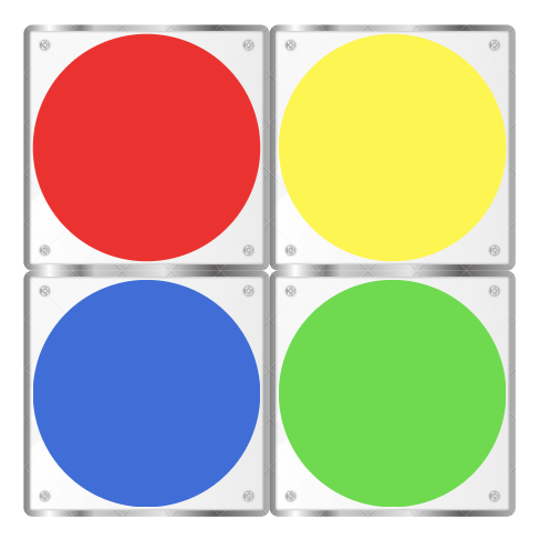
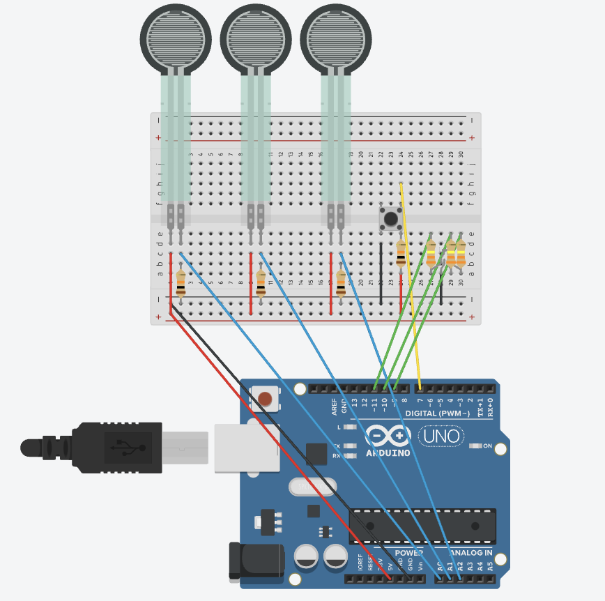
In the standard version of the game, participants spin a wheel to determine a color and a designated body part (hands or feet). Subsequently, players must position the indicated body part onto the corresponding colored circle on the Twister mat. The objective is to avoid losing balance, and if the player falls down, they lose. For the physical setup in my version, I plan to craft the Twister mat using acrylic sheets. Under each colored circle, I will integrate force sensors to detect whether a player has placed their palm or foot on the designated spot. This modification eliminates the need for multiple players while retaining the essence of the original game.
Spinning wheel
Digital Interface with p5js:
Utilizing the p5js interface, I intend to create a virtual spinner that dictates the next move for the player. p5js will not only control the wheel spinning but also manage the game score and determine win/loss conditions and the start & end of the game.
Additional Gameplay Elements:
To introduce a new challenge, I plan to incorporate ultrasonic sensors. In the classic game there is one option on the wheel that if landed on, the users have to keep their body part in the air. In this version, When the wheel lands on a specific option, players must extend their hands or feet to a particular distance, as detected by the sensors.
Wheel Spinning Mechanism: Considering the physical nature of the game that actively uses the player’s hands, I’m exploring two potential options for spinning the wheel through p5js instead of directly clicking it on the laptop. One approach involves a switch on the Twister mat that, when pressed, triggers the p5js interface to spin the wheel. Alternatively, I’m considering a voice-activated mechanism where saying the word ‘spin’ initiates the wheel rotation.
Twister mat with acrylic sheets
Arduino Circuit: The Arduino circuit will be straightforward, connecting switches and force sensors to the Twister mat. However, I’m intrigued by the possibility of incorporating flex sensors/motors to introduce more complexity and fun to the game. These additions could potentially respond to the player’s movements, making the experience even more interactive.
Considerations:
While developing the game, I recognize the need to redefine the losing condition for a single-player setup. Unlike the traditional game where a player falls to signify defeat, I aim to explore alternative practical criteria that maintain the challenge and excitement without relying on physical falls in a solo context. By combining physical and digital elements, along with creative twists to the gameplay, I hope to transform Twister into a captivating and entertaining game experience.
For my final project of the semester, I want to incorporate my love for music, inspired by an idea I had worked on before in a different class last semester. In Making Music, we had an assignment to create a drum kit out of “everyday” sounds. It was really interesting to listen to music tracks created purely out of “everyday” sounds. For my project I want to create an interactive drum kit, where the user presses on a button to choose one of the multiple themes available. Then the user can use their fingers to hit the “drum plates”, which are going to be placed on force sensors. Depending on which theme they are on, they would get different sounds from each plate.I will include one regular drum kit and multiple unusual ones. Additionally, I want to include a feature where a user can record up to 10 seconds of music as well. When the recording is complete it is attached to previous users’ recordings so that at the end of the night, I have a recording of different people playing different drum kits each using their own style. I also would like to include a feature that allows users to listen to the cumulative recording at any point. My idea is to mix everyday sounds, to sound like unusual drum kits, and allow users to improvise for a bit and mashup their improvisation later on to have a piece of music that is reflective of our different personalities. My idea is to implement it as a virtual studio, each room in the studio has a different theme and a different drum kit.
Input from Arduino: Force sensors, button
Output from Arduino: RGB LED that displays different colors depending on what theme they are on
Arduino code:
The Arduino code will read values from the sensors and send them to p5js, it will also change the color of the RGB LED by receiving a value from p5js and acting accordingly
Input from P5js: Space bar to record a short performance, if possible. Enter to return to homepage.
Output from P5js: Sounds, screen display
P5js code:
The P5js code will control the display of the themes by reading the switch values sent from the Arduino. It will also trigger sound files according to the data sent from the force sensors by the Arduino. Additionally, it would control the recording process and the playback of the recordings.
Schematic:
Arduino schematic
This is the initial design of my home p5js screen, but I have not designed the other themed screens yet, so I am not sure if I would stick with the same vibe for my project. I might change it if necessary when I am implementing the other screens as well:
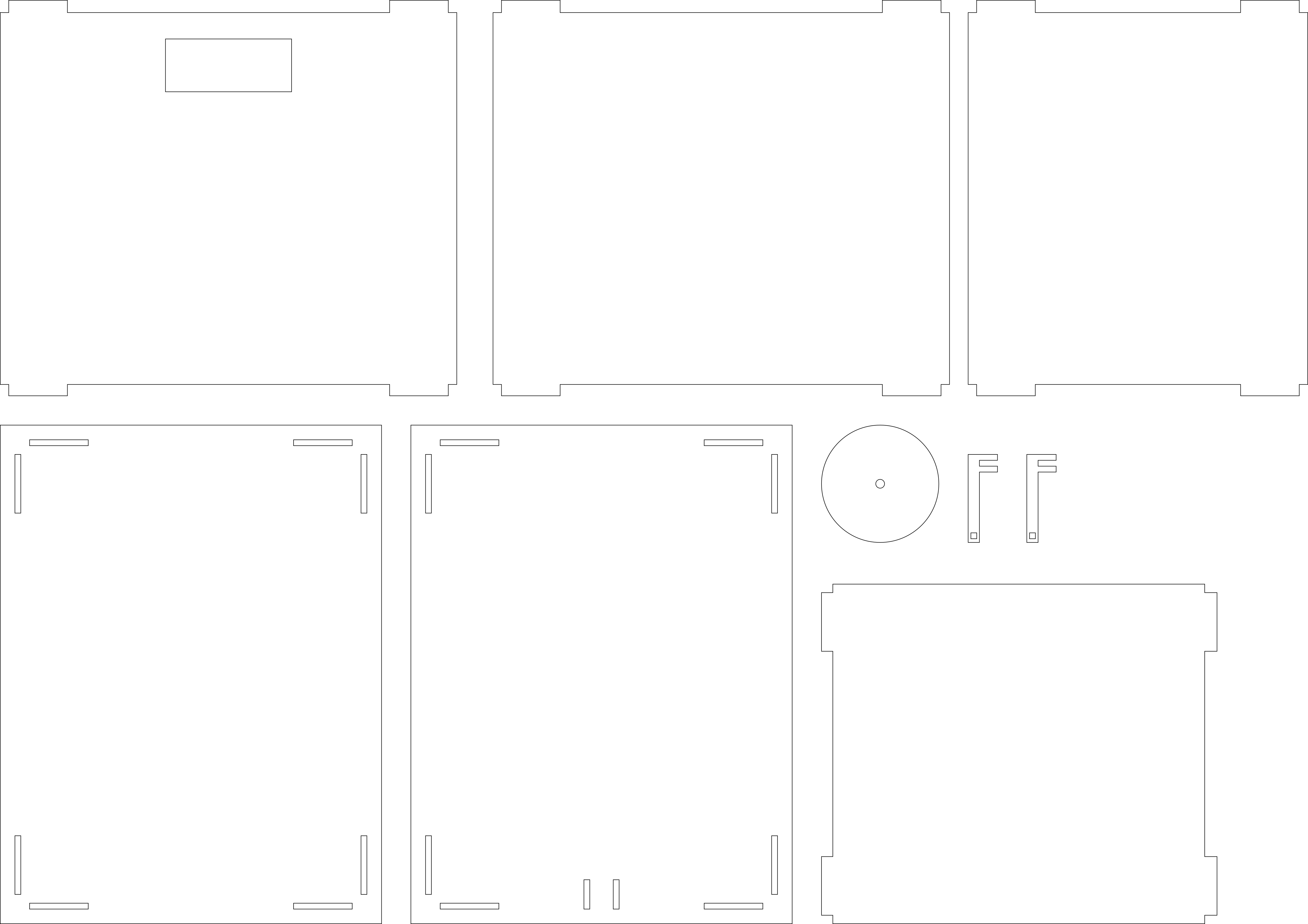
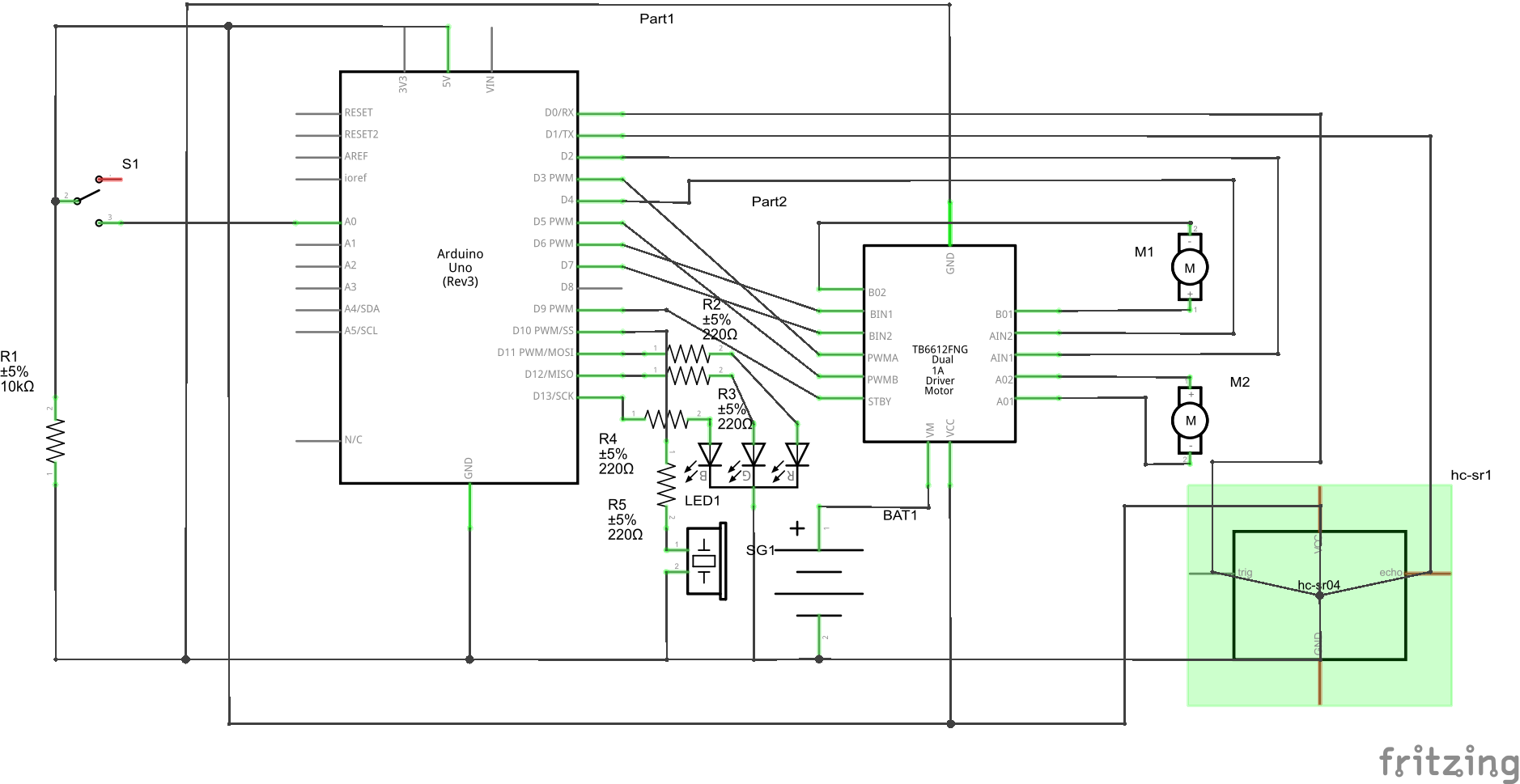
For the final project, I plan to make a “Cyber-Pet”. I have always wanted a pet but my parents won’t let me, so I want to make one (or as close as it can get XD). This pet can get different emotions when the user interacts with it through typing in prompts. Its emotions are generated through services provided by OpenAI’s GPT 3.5 API. The emotions of the pet are scaled from 1 to 10, with 1 being very unhappy and 10 being very happy. When the pet gives back a response, the buzzer will run and make sounds. The angrier the pet is, the buzzer sounds will be higher pitched and more rapid. But if the pet is happy, the sounds will be more calm and pleasant (as pleasant as a buzzer can be). The pet will be equipped with 2 motors that allow the pet to move. It will also be equipped with a distance sensor. If the user inputs a certain command, it will trigger a condition. If the pet is happy, the pet will move towards the user as if looking for a hug. Otherwise, the pet will attempt to run away from the user while making loud noises with the buzzer.
The Arduino board can be put inside a box made of wooden planks, and apart from the two back wheels driven by motors, it should also have another assistive wheel so that it can stand upright. The CAD drawing for the laser cutting of the board is shown below:
Below is the schematic for the Arduino board:
I will start cutting out the outer boards tomorrow, and then assemble and program the board.
I really love cars and driving, which is why I’m super excited about creating a car for my final project. My solidified idea is to build a remotely controlled car using p5.js. The main goal is to replicate the experience of driving a manual car by providing complete control through the p5.js sketch.
In this project, I plan to incorporate a webcam, giving users a live video feed in the sketch that mimics a car window. This way, it feels like you’re actually inside the car while controlling it remotely. The sketch will also feature a gear stick, allowing users to adjust the speed as if they are accelerating in a real car.
The cool thing about this project is that it aims to seamlessly bring in a webcam, providing users with a live visual experience on p5.js. This goes beyond physical boundaries, allowing for easy remote control, even if the car is far away. I’m also thinking of adding a distance sensor to enhance safety by alerting users about potential collisions.
Here’s a basic visualization of what the sketch might look like initially:
Arduino Program:
Input:
Distance sensor sending distance values to the P5JS to check for possible collisions.
Output:
Motors rotating wheels based on the received instructions from P5JS.
Leds turning on/off based on the received instructions from P5JS.
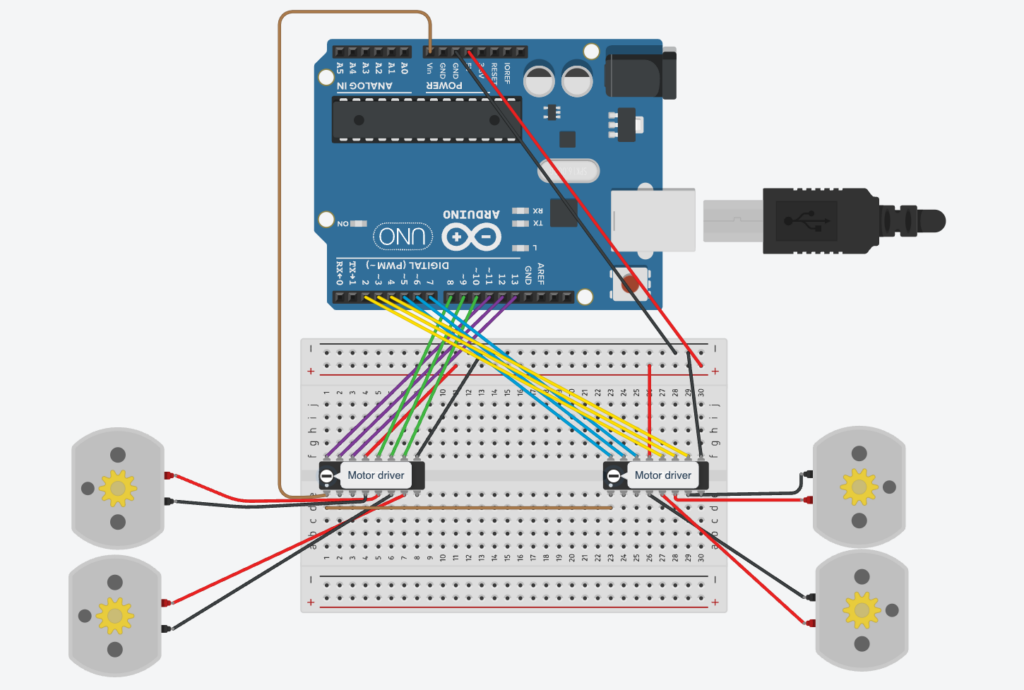
Also, I have designed an initial circuit for controlling the four wheels of the car:
Circuit
P5JS Program:
Input:
Gear value that changes the maximum speed of the car.
Keyboard controls that move the car.
Output:
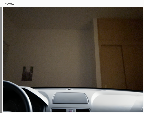
Road view stream of the car displayed using a webcam covered by a car window as shown in the following figure.
A car in my dorm
Alert triggered when the distance from the car becomes less than a certain threshold.
Perhaps additional elements will be incorporated as I progress through the implementation process.
Reading this book section, something that catches me is about glasses. Before it never occurred to me that glasses were used instead of worn. They were so common that I forgot they were for disabilities in the eyes. Also, the design for glasses right now focuses more on aesthetics than practicality. It has come to the point that some people wear fake glasses that don’t really do anything because it makes them look better. It is interesting to see how this can be applied to hearing aids or even prosthetics. However, I think this is unlikely to be the case. I believe that this transition from a tool to a fashionable decoration is not replicable for other tools used to address disabilities. Apart from simply being something to fix disabilities, glasses also suggest that the person is smart or knowledgeable because reading a lot makes people’s eyesight decrease. But for other prosthetics or disability aids they do not suggest such meaning. others might even say they are being careless. Therefore subconsciously, people will not think having such things is good, and thus have negative feelings about it no matter how fashionable they are.
As mentioned later, the iPod part also was very interesting. The author used the iPod to demonstrate appliances. However, I think the iPod is just a product that got stuck between sound quality and portability. For the sound quality, the iPod is obviously not even close to as good as other big professional speakers and stuff. For portability, it is just a tiny bit smaller in size compared to that of a cell phone. Therefore I think this product is not successful and cannot be used as an example of a successful appliance. Maybe only mentioning cutlery would be better:)
I used a photoresistor as input to control the position of the sphere.
p5js:
let xcord = 0;
let left=0;
let right=0;

function setup() {
  createCanvas(640, 480);
}

function draw() {
  background("white");

  if (!serialActive) {
    text("Press Space Bar to select Serial Port", 20, 30);
  } else {
    text("Connected", 20, 30);

    ellipse(xcord,height/2,100,100);
    console.log(xcord);

  }

}

function keyPressed() {
  if (key == " ") {
    // important to have in order to start the serial connection!!
    setUpSerial();
  }
}

function readSerial(data) {


  if (data != null) {

    let fromArduino = trim(data);

    xcord = int(fromArduino);

  }
}
Arduino:
int inPin = A0;

void setup() {
  // Start serial communication so we can send data
  // over the USB connection to our p5js sketch
  Serial.begin(9600);

  pinMode(LED_BUILTIN, OUTPUT);
  pinMode(inPin, INPUT);
}

void loop() {

  digitalWrite(LED_BUILTIN, HIGH);  // led on while receiving data


  int sensor = analogRead(A0);
  delay(5);
  Serial.println(sensor - 300);

  digitalWrite(LED_BUILTIN, LOW);
}
2.
p5js:
let ycord;

function setup() {
  createCanvas(640, 480);
  textSize(18);
}

function draw() {

  if (!serialActive) {
    text("Press Space Bar to select Serial Port", 20, 30);
  } else {
    text("Connected", 20, 30);

  }

  if (mouseIsPressed) {
    ycord=mouseY;
    console.log(ycord);
  }
}

function keyPressed() {
  if (key == " ") {
    // important to have in order to start the serial connection!!
    setUpSerial();
  }
}

function readSerial(data) {

  if (data != null) {
    let fromArduino = trim(data);

    let sendToArduino = ycord + "\n";
    writeSerial(sendToArduino);
    console.log("sent");
  }

}
Arduino:
int inPin = A0;
int outpin = 8;

void setup() {
  // Start serial communication so we can send data
  // over the USB connection to our p5js sketch
  Serial.begin(9600);

  pinMode(LED_BUILTIN, OUTPUT);
  pinMode(inPin, INPUT);
  pinMode(outpin, INPUT);
}

void loop() {

  digitalWrite(LED_BUILTIN, HIGH);  // led on while receiving data

  int brightness = Serial.parseInt();
  if (Serial.read() == '\n') {
    digitalWrite(outpin, HIGH);
    delay(brightness/100);

    digitalWrite(outpin, LOW);
    delay(4.80-brightness/100);
  }
  Serial.println(brightness);
}
3. It works but the lag is insane.
Arduino:
int inPin = A0;
int outpin = 8;

void setup() {
  // Start serial communication so we can send data
  // over the USB connection to our p5js sketch
  Serial.begin(9600);

  pinMode(LED_BUILTIN, OUTPUT);
  pinMode(inPin, INPUT);
  pinMode(outpin, INPUT);
}

void loop() {
  digitalWrite(LED_BUILTIN, LOW);

  while (Serial.available()) {
    // led on while receiving data
    digitalWrite(LED_BUILTIN, HIGH);
    int left = Serial.parseInt();
    if (Serial.read() == '\n') {

      int sensor = analogRead(A0);
      Serial.println(sensor);
    }
    if (left >= 350 && left <= 360) {
      digitalWrite(outpin, HIGH);
    } else {
      digitalWrite(outpin, LOW);
    }
  }
  int sensor = analogRead(A0);
  Serial.println(sensor);
}
P5:
let velocity;
let gravity;
let position;
let acceleration;
let wind;
let drag = 0.99;
let mass = 50;

function setup() {
  createCanvas(640, 360);
  noFill();
  position = createVector(width/2, 0);
  velocity = createVector(0,0);
  acceleration = createVector(0,0);
  gravity = createVector(0, 0.1*mass);
  wind = createVector(0,0);
}

function draw() {

  background(255);
  applyForce(wind);
  applyForce(gravity);
  velocity.add(acceleration);
  velocity.mult(drag);
  position.add(velocity);
  acceleration.mult(0);
  ellipse(position.x,position.y,mass,mass);
  if (position.y > height-mass/2) {
      velocity.y *= -0.9;  // A little dampening when hitting the bottom
      position.y = height-mass/2;
    }
}

function readSerial(data) {
    ////////////////////////////////////
    //READ FROM ARDUINO HERE
    ////////////////////////////////////

    if (data != null) {
    // make sure there is actually a message

    let fromArduino = trim(data);

    //console.log(fromArduino);
    let sensorVal = int(fromArduino);

    if (sensorVal < 600){
      wind.x=1;
    }
    else if(sensorVal >= 600 && sensorVal < 800){
      wind.x = 0;
    }

    else {
      wind.x = -1;
    }
//           //////////////////////////////////
//           //SEND TO ARDUINO HERE (handshake)
//           //////////////////////////////////
  }
  else{
    console.log("empty input");
  }
//height of ball sent to arduino to check if ball on floor or not
  let sendToArduino = position.y + 0.5 * mass + "\n";
  writeSerial(sendToArduino);

}

function applyForce(force){
  // Newton's 2nd law: F = M * A
  // or A = F / M
  let f = p5.Vector.div(force, mass);
  acceleration.add(f);
}

function keyPressed(){
  if (keyCode==LEFT_ARROW){
    wind.x=-1;
  }
  if (keyCode==RIGHT_ARROW){
    wind.x=1;
  }
  // if (key==' '){
  //   mass=random(15,80);
  //   position.y=-mass;
  //   velocity.mult(0);
  // }
  if (key == " ") {
    if (!serialActive) {
      setUpSerial();
      console.log("serial")
    }
    mass=random(15,80);
    position.y=-mass;
    velocity.mult(0);
  }
}
While going through the text, a specific passage that took my attention is the discussion about hearing aids. Unlike glasses, whose design has undergone comparatively less change, the writer highlights the evolving nature of hearing aids, emphasizing not only the modifications in their appearance but also the constant transformation of their discreet placement.
And in the part where, ‘Simple meets universal’, the author explores the complexities of designing for special needs, especially when dealing with a minority of the population. On one hand, there is a compelling business argument against further fragmenting the market by tailoring designs for small percentages of users. The concern here is that such a specialized approach might limit the product’s reach and economic viability.
Conversely, the concept of inclusive design, also known as universal design, introduces a principle-based contention. Inclusive design, by definition, aims to cater to the entire population. This definition intertwines two critical aspects: the acknowledgment that individuals possess varying abilities, and a recognition that people may have diverse needs and preferences regardless of their abilities. The former is commonly addressed through multimodal interfaces, incorporating visual, audible, and tactile cues to accommodate those with impaired touch, hearing, and/or sight. Meanwhile, the latter is often managed through multifunctional platforms, incorporating numerous features to appeal to a broad range of users.
A central question raised by the author is whether the pursuit of universal design, aiming to accommodate a diverse user base, might inadvertently lead to overly complex designs. There is a tension between the goal of inclusivity and the risk of creating designs that are intricate and potentially challenging to use. This prompts a consideration of how truly inclusive such designs are, and whether there are insights to be gained from navigating these design complexities.
Something that uses only one sensor on Arduino and makes the ellipse in p5 move on the horizontal axis, in the middle of the screen, and nothing on arduino is controlled by p5.
P5JS code
let redValue = 0;
let transparency = 255;

function setup() {
  createCanvas(640, 480);
  textSize(18);
}

function draw() {
  if (key == " ") {
    initiateSerialConnection();
  }

  background(map(redValue, 0, 1023, 0, 255), 255, 255);
  fill(255, 0, 255, map(transparency, 0, 1023, 0, 255));

  if (!isSerialActive) {
    text("Press Space Bar to select Serial Port", 20, 30);
  } else {
    ellipse(redValue / 2, 240, 100, 100);
  }
}

function keyPressed() {
  if (key == " ") {
    initiateSerialConnection();
  }
}

function readSerial(data) {
  if (data != null) {
    let fromArduino = split(trim(data), ",");
    if (fromArduino.length == 2) {
      redValue = int(fromArduino[0]);
      transparency = int(fromArduino[1]);
    }
  }
}
Arduino code
void setup() {
 Serial.begin(9600);
 pinMode(LED_BUILTIN, OUTPUT);
// start the handshake
 while (Serial.available() <= 0)
{
   Serial.println("0,0"); // send a starting message
   delay(300);            // wait 1/3 second
 }
}
void loop()
{
 // wait for data from p5 before doing something
   while (Serial.available())
{
   digitalWrite(LED_BUILTIN, HIGH); // led on while receiving data
 // Read sensor value
 int sensorValue = analogRead(A0);
  Serial.print(sensorValue);
 // Map sensor value to screen width
 int screenValue = map(sensorValue, 0, 1023, 0, 800);
 // Send mapped value to p5.js
 Serial.println(screenValue);
 delay(50); //    for stability
}
digitalWrite(LED_BUILTIN, LOW);
}
Exercise 2
Something that controls the LED brightness from p5. LED’s brightness is changed by mouseX and the other’s by mouse Y.
P5JS code
let rVal = 0;
let alpha = 255;
let left = 0; // True (1) if mouse is being clicked on left side of screen
let right = 0; // True (1) if mouse is being clicked on right side of screen
function setup() {
 createCanvas(255, 255);
 textSize(18);
}
function draw() {
 // one value from Arduino controls the background's red color
 background(map(rVal, 0, 1023, 0, 255), 255, 255);
 // the other value controls the text's transparency value
 fill(255, 0, 255, map(alpha, 0, 1023, 0, 255));
 if (!serialActive) {
   text("Press Space Bar to select Serial Port", 20, 30);
 } else {
   text("Connected", 20, 30);

   // Print the current values
   text('rVal = ' + str(rVal), 20, 50);
   text('alpha = ' + str(alpha), 20, 70);
 }
 // click on one side of the screen, one LED will light up
 // click on the other side, the other LED will light up
 if (mouseIsPressed) {
   if (mouseX <= width / 2) {
     left = 1;
   } else {
     right = 1;
   }
 } else {
   left = right = 0;
 }
}
function keyPressed() {
 if (key == " ") {
   // important to have in order to start the serial connection!!
   setUpSerial();
 }
}
// This function will be called by the web-serial library
// with each new *line* of data. The serial library reads
// the data until the newline and then gives it to us through
// this callback function
function readSerial(data) {
 ////////////////////////////////////
 //READ FROM ARDUINO HERE
 ////////////////////////////////////
 if (data != null) {
   // make sure there is actually a message
   // split the message
   let fromArduino = split(trim(data), ",");
   // if the right length, then proceed
   if (fromArduino.length == 2) {
     // only store values here
     // do everything with those values in the main draw loop

     // We take the string we get from Arduino and explicitly
     // convert it to a number by using int()
     // e.g. "103" becomes 103
     rVal = int(fromArduino[0]);
     alpha = int(fromArduino[1]);
   }
   //////////////////////////////////
   //SEND TO ARDUINO HERE (handshake)
   //////////////////////////////////

   let sendToArduino = mouseX + "," + mouseY + "\n";
   writeSerial(sendToArduino);
 }
}
Arduino code
int leftLedPin = 2;
int rightLedPin = 5;
void setup() {
 // Start serial communication so we can send data
 // over the USB connection to our p5js sketch
 Serial.begin(9600);
 // We'll use the builtin LED as a status output.
 // We can't use the serial monitor since the serial connection is
 // used to communicate to p5js and only one application on the computer
 // can use a serial port at once.
 pinMode(LED_BUILTIN, OUTPUT);
 // Outputs on these pins
 pinMode(leftLedPin, OUTPUT);
 pinMode(rightLedPin, OUTPUT);
 // Blink them so we can check the wiring
 digitalWrite(leftLedPin, HIGH);
 digitalWrite(rightLedPin, HIGH);
 delay(200);
 digitalWrite(leftLedPin, LOW);
 digitalWrite(rightLedPin, LOW);
 // start the handshake
 while (Serial.available() <= 0) {
   digitalWrite(LED_BUILTIN, HIGH); // on/blink while waiting for serial data
   Serial.println("0,0"); // send a starting message
   delay(300);            // wait 1/3 second
   digitalWrite(LED_BUILTIN, LOW);
   delay(50);
 }
}
void loop() {
 // wait for data from p5 before doing something
 while (Serial.available()) {
   digitalWrite(LED_BUILTIN, HIGH); // led on while receiving data
   int posX = Serial.parseInt();
   int posY = Serial.parseInt();
   if (Serial.read() == '\n') {
     analogWrite(leftLedPin, posX);
     analogWrite(rightLedPin, posY);
     int sensor = analogRead(A0);
     delay(5);
     int sensor2 = analogRead(A1);
     delay(5);
     Serial.print(sensor);
     Serial.print(',');
     Serial.println(sensor2);
   }
 }
 digitalWrite(LED_BUILTIN, LOW);
}
Exercise 3
Bouncing ball: potentiometer is used as the analog sensor to control the breeze.
P5JS code
let velocity;
let gravity;
let position;
let acceleration;
let breeze;
let drag = 0.99;
let mass = 50;
let heightOfBall = 0;
function setup() {
  createCanvas(640, 360); // Create a canvas of 800x400 pixels

  noFill();
  position = createVector(width/2, 0);
  velocity = createVector(0,0);
  acceleration = createVector(0,0);
  gravity = createVector(0, 0.5*mass);
  breeze = createVector(0,0);
}
function draw() {
  background(215);
  fill(0);

  if (!serialActive) {
    text("Press the space bar to select the serial Port", 20, 30);
  }
  else
  {
    text("Arduino is connected! Press b to jump.", 20, 30);

  applyForce(breeze);
  applyForce(gravity);
  velocity.add(acceleration);
  velocity.mult(drag);
  position.add(velocity);
  acceleration.mult(0);
  ellipse(position.x,position.y,mass,mass);

  if (position.y > height-mass/2) {
      velocity.y *= -0.9;  // A little dampening when hitting the bottom
      position.y = height-mass/2;

    heightOfBall = 0;

    }
    else {
      heightOfBall = 1;
    }
  }
}
function applyForce(force){
  // Newton's 2nd law: F = M * A
  // or A = F / M
  let f = p5.Vector.div(force, mass);
  acceleration.add(f);
}
function keyPressed() {
  if (key == " ") {
    // important to have in order to start the serial connection!!
    setUpSerial();
  }
  else if (key=='b'){
    mass=random(15,80);
    position.y=-mass;
    velocity.mult(0);
  }
}
// this callback function
function readSerial(data) {
    ////////////////////////////////////
    //READ FROM ARDUINO HERE
    ////////////////////////////////////

     if (data != null) {
    // make sure there is actually a message

    let fromArduino = split(trim(data), ",");

       // if the right length, then proceed
    if (fromArduino.length == 1) {
//sensor value is the input from potentiometer
      let sensorVal = int(fromArduino[0]);

//potentiometer value ranges from 0 - 1023
//for values less than 400,wind blows to right
      if (sensorVal < 400){
        breeze.x=1
      }
//if value between 400 and 500, wind stops so ball stops
      else if(sensorVal >= 400 && sensorVal < 500){
        breeze.x = 0
      }
//if value greater than 500, wind blows to left
      else {
        breeze.x = -1
      }
          //////////////////////////////////
          //SEND TO ARDUINO HERE (handshake)
          //////////////////////////////////
    }
//height of ball sent to arduino to check if ball on floor or not
    let sendToArduino = heightOfBall  + "\n";
    writeSerial(sendToArduino);
  }
}
Arduino code
const int poten_pin = A0;
const int ledPin = 2;
void setup() {
 Serial.begin(9600); // Start serial communication at 9600 bps
 pinMode(LED_BUILTIN, OUTPUT);
 pinMode(ledPin, OUTPUT);
 pinMode(poten_pin, INPUT);
 // start the handshake
 while (Serial.available() <= 0) {
   digitalWrite(LED_BUILTIN, HIGH); // on/blink while waiting for serial data
   Serial.println("0,0"); // send a starting message
   delay(300);            // wait 1/3 second
   digitalWrite(LED_BUILTIN, LOW);
   delay(50);
 }
}
void loop()
{
 // wait for data from p5 before doing something
   while (Serial.available())
   {
     digitalWrite(LED_BUILTIN, HIGH);
     digitalWrite(ledPin, LOW);
//read the position of ball from p5
     int position = Serial.parseInt();

     if (Serial.read() == '\n') {
       // Read potentiometer value
     int sensorValue = analogRead(poten_pin);
     //send value to p5
     Serial.println(sensorValue);
     }
//if ball is touching the ground i.e. height is zero, turn LED on
     if (position == 0)
     {
       digitalWrite(ledPin, HIGH);
     }
     else{
       digitalWrite(ledPin, LOW);
     }
   }
     digitalWrite(LED_BUILTIN, LOW);
   }