Concept)
There were two conditions I wanted to meet when creating this instrument
– it should involve both hands
– it should be able to play different notes separately (i.e. the sound is not continuous)
It naturally made sense to have one of the hands be responsible of how long a note should be played, and the other hand to specify the note. I saw different videos for inspiration and saw instruments that use the distance to decide the note to be played.
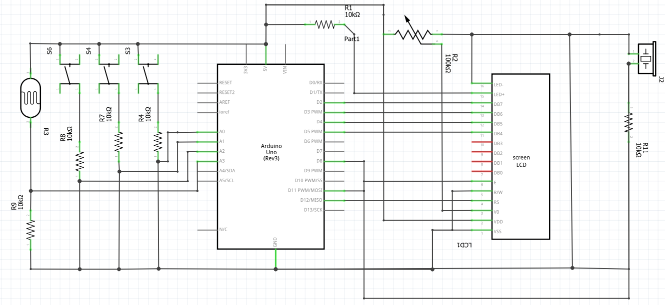
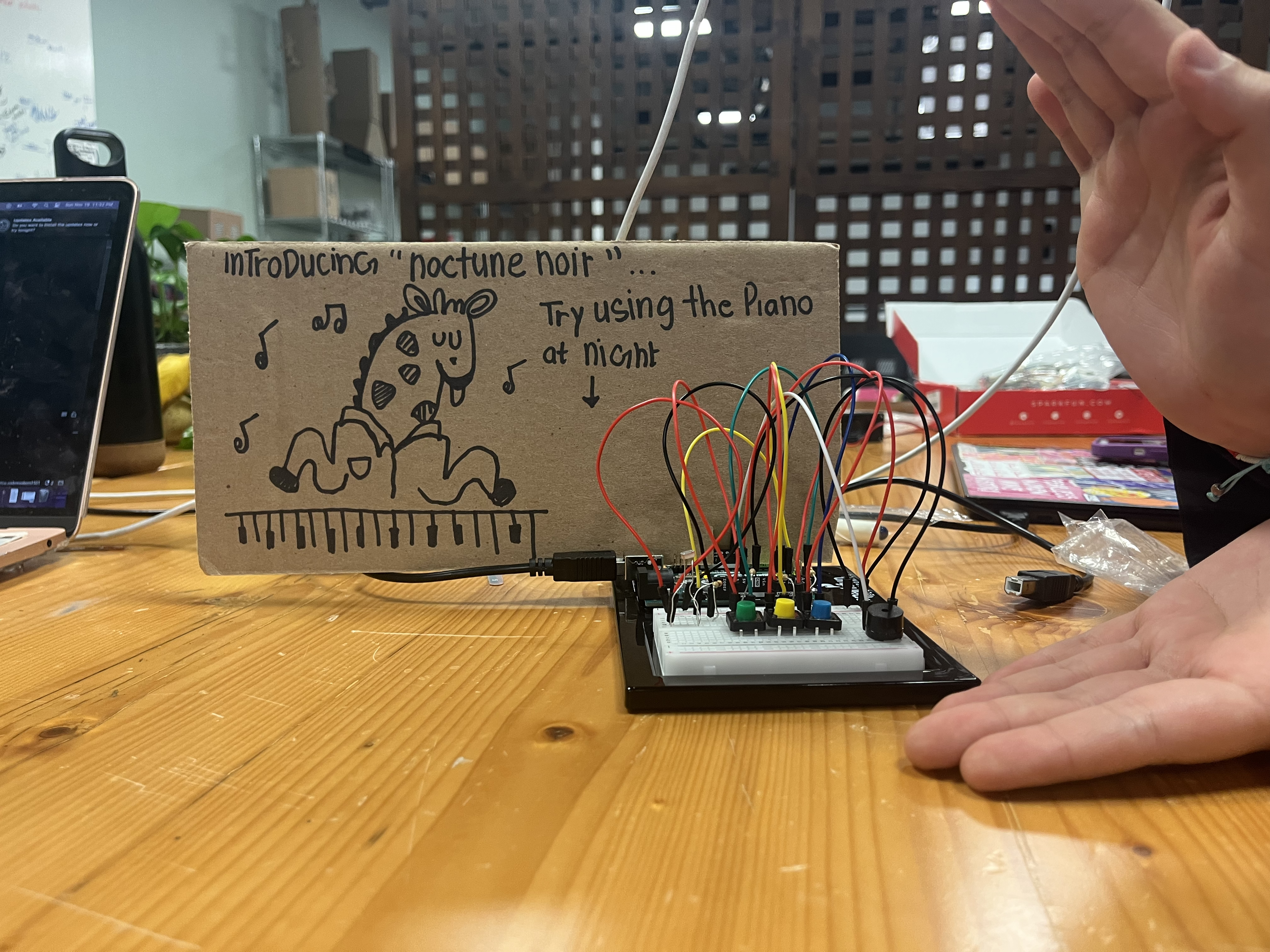
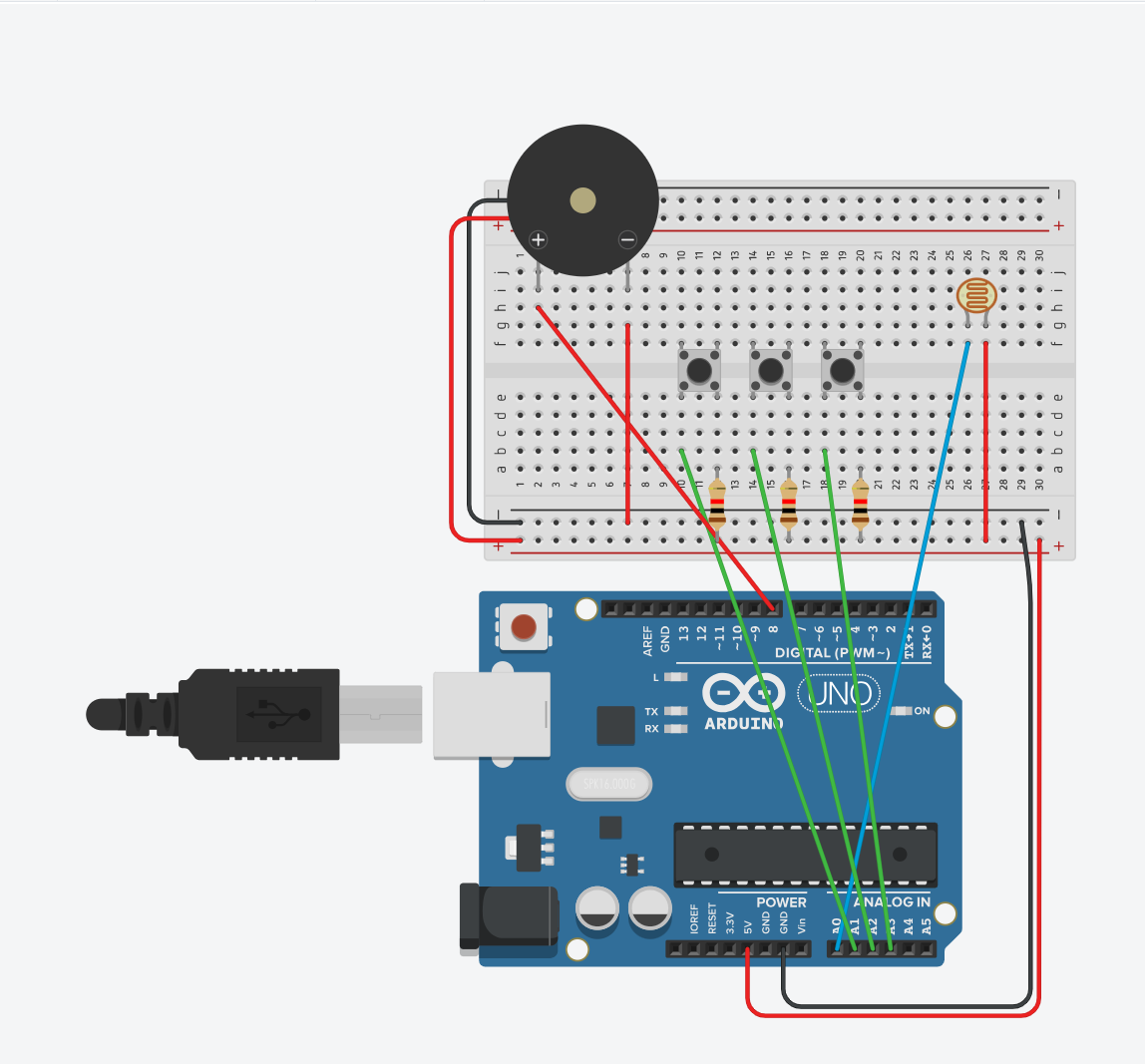
Production)
Code)
int trig = 10;
int echo = 11;
int light = 5;
long  duration;
long  distance;
int   buttonState;


void setup() {
  pinMode(echo, INPUT);
  pinMode(trig, OUTPUT);
  pinMode(light, OUTPUT);
  Serial.begin(9600);
}

void loop() {
  digitalWrite(trig, LOW);
  delayMicroseconds(2);
  digitalWrite(trig, HIGH);
  delayMicroseconds(10);
  digitalWrite(trig, LOW);
  duration = pulseIn(echo, HIGH);
  distance = (duration / 2) * 0.0344;
  /*
    duration = time it took for ultrasonic pulse to travel to and back from the object
    distance equation: conversion from duration to distance
    because the duration includes the travel time to and back from the object,
      divided by 2
    multiplied by 0.0344: speed of sound in air (in room temperature
                            = 343 m/s ==> convert to cm
  */


  int notes[7] = {261, 294, 329, 349, 392, 440, 494};
  //C, D, E, F, G, A, B

  buttonState = analogRead(A1);

  int sound;

  if (distance < 0 || distance > 50 || buttonState < 100) {
      sound = -1;
  } else if (distance <= 5) {
      sound = 0;
  } else if (distance <= 10) {
      sound = 1;
  } else if (distance <= 15) {
      sound = 2;
  } else if (distance <= 20) {
      sound = 3;
  } else if (distance <= 30) {
      sound = 4;
  } else if (distance <= 40) {
      sound = 5;
  } else {
      sound = 6;
  }

  if (sound != -1) {
      digitalWrite(light, HIGH);
      Serial.println(sound);
      tone(12, notes[sound]);
  } else {
      noTone(12);
      digitalWrite(light, LOW);
  }

}
I think the most interesting part of this code was figuring out how to convert the duration to distance, and the distance to different notes.
Future Improvements)
I think it’s be interesting if I can connect a force censor, for instance, to create the beat on the background. Then, it would have a simple instrument that consists of the base beat (like a drum) and the melody part through the hands.