New Concept:
In the true spirit of being a bit indecisive, I’ve opted for a puzzle game. It all started with the certainty that I’d be dealing with a joystick in my physical computing adventures. So, brainstorming around this joystick, the idea of a picture puzzle game struck me. The concept is simple: solve the puzzle using the joystick. To add a personal touch, I thought it’d be cool to let players use their own pictures for the puzzle. I mean, puzzles can be dull, right? So, why not make it more fun by solving a puzzle of yourself?
P5.js Code:
I’ve made some progress in coding the game using P5.js. The groundwork includes screens for welcoming players, providing instructions, selecting difficulty levels, activating the camera, and of course, the puzzle screen itself. The code varies in complexity since it’s still a work in progress. Here’s a snippet that deals with turning a captured picture into a puzzle, which excites me the most.
function captureAndSetupPuzzle(video) {
  if (video) {
    source = video.get();
    source.loadPixels(); // Ensure pixels are loaded
 if (source.width > 0 && source.height > 0) {
    // Resize the source image to fit the canvas
    source.resize(width, height);
    video.hide();

    w = Math.floor(width / cols);
    h = Math.floor(height / rows);

    for (let i = 0; i < cols; i++) {
      for (let j = 0; j < rows; j++) {
        let x = i * w;
        let y = j * h;
        let img = source.get(x, y, w, h); // Get a portion of the image for each tile

        if (i === cols - 1 && j === rows - 1) {
          board.push(-1);
          puzzle.tiles.push(new Tile(-1, img));
        } else {
          let index = i + j * cols;
          board.push(index);
          puzzle.tiles.push(new Tile(index, img));
        }
      }
    }

    puzzle.board = board.slice();
    puzzle.simpleShuffle(puzzle.board);

    currentScreen = 'game';
    puzzle.startTimer();
  } else {
    console.error("Error loading the video source");
    }
  }
}

function setup() {
  createCanvas(600,400);
  //createCanvas(displayWidth, displayHeight);

  video = createCapture(VIDEO);
  video.size(400, 400);
  video.position(0, 0);
  video.hide();


  let timerDuration ;
  let level;

  puzzle = new Puzzle(cols, rows, timerDuration, level); // Example level: 3x3 grid, 600 seconds timer
}
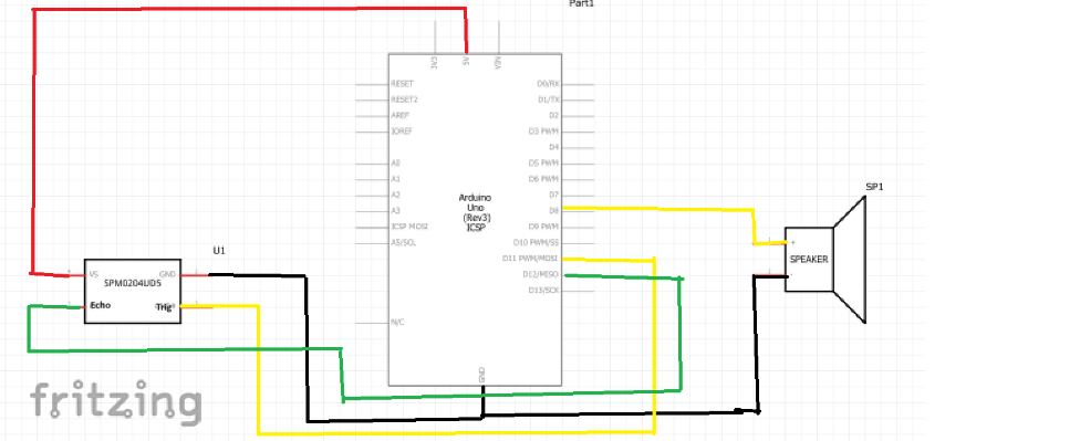
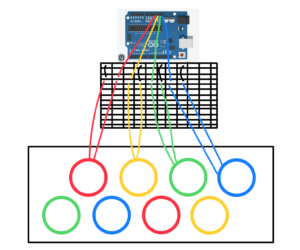
Arduino Code:
Additionally, I’ve been working on Arduino code. It seems mostly complete for now, though I might tweak it as my P5 code progresses. The aim of this code is to control the button movements and the movements of the puzzle tiles using the joystick.
const int XbuttonPin = 2;
const int SbuttonPin = 3;
const int TbuttonPin = 4;
const int CbuttonPin = 5;
const int joystickXPin = A0; // Analog pin for joystick X-axis
const int joystickYPin = A1; // Analog pin for joystick Y-axis
const int threshold = 50; // Threshold for joystick sensitivity
//bool isDifficulty = false;

void setup() {
  Serial.begin(9600);
  pinMode(XbuttonPin, INPUT_PULLUP);
  pinMode(SbuttonPin, INPUT_PULLUP);
  pinMode(TbuttonPin, INPUT_PULLUP);
  pinMode(CbuttonPin, INPUT_PULLUP);
}

void loop() {
  if (digitalRead(XbuttonPin) == LOW) {
    Serial.println("MOUSE_CLICK");
    delay(1000); // Debounce delay
  }

  if (digitalRead(SbuttonPin) == LOW) {
    Serial.println('2');
    delay(100); // Debounce delay
  }

  if (digitalRead(TbuttonPin) == LOW) {
    Serial.println('1');
    delay(10000); // Debounce delay
  }

  if (digitalRead(CbuttonPin) == LOW) {
    Serial.println('3');
    delay(100); // Debounce delay
  }

  if (digitalRead(TbuttonPin) == LOW) {
    Serial.println('C');
    delay(100); // Debounce delay
  }

  int xVal = analogRead(joystickXPin); // Read X-axis value
  int yVal = analogRead(joystickYPin); // Read Y-axis value

  if (xVal < 512 - threshold) {
    Serial.println("LEFT");
    delay(100); // Debounce delay
  } else if (xVal > 512 + threshold) {
    Serial.println("RIGHT");
    delay(100); // Debounce delay
  }

  if (yVal < 512 - threshold) {
    Serial.println("DOWN");
    delay(100); // Debounce delay
  } else if (yVal > 512 + threshold) {
    Serial.println("UP");
    delay(100); // Debounce delay
  }
}
Challenges popped up, especially when translating mouse movements to joystick actions. Initially, I aimed to use mouse clicks and key presses in my P5.js code, thinking I could easily convert them to buttons and switches. But handling joystick movements, considering up, down, left, and right, turned out more intricate than merely clicking a mouse to move a tile.
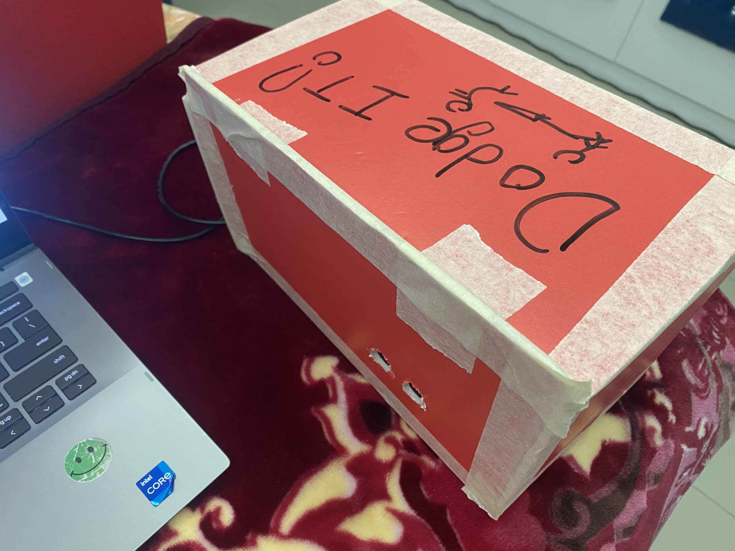
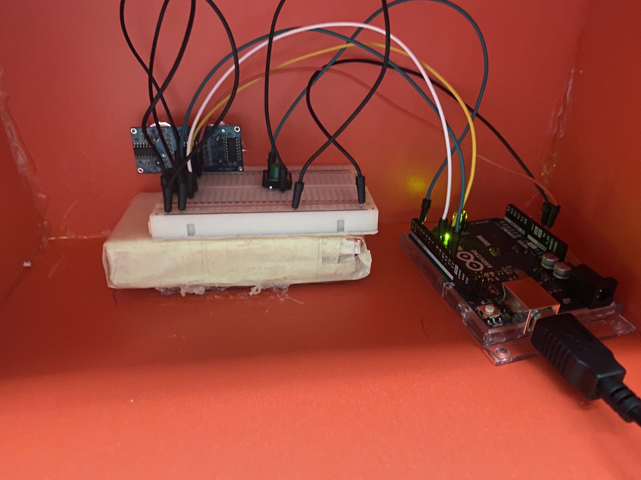
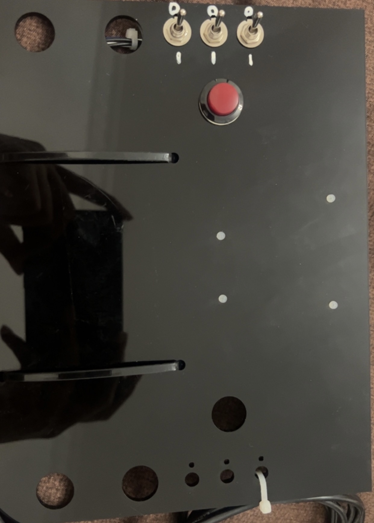
Prototype:
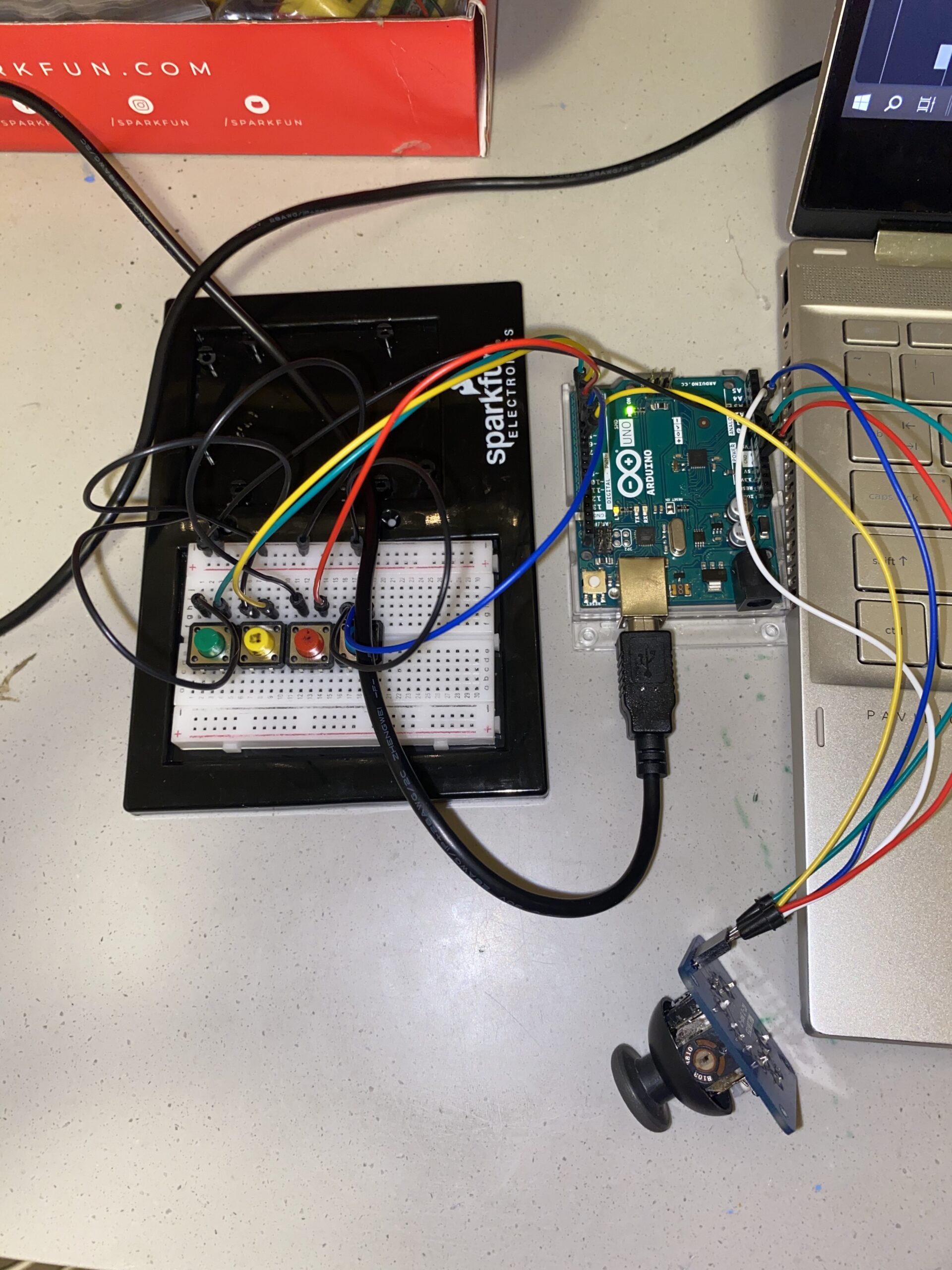
Tasks on my to-do list seem endless because, well, I’m a bit of a perfectionist. At the moment, I’m focusing on crafting a case for my Arduino and breadboard. Simultaneously, I’m tirelessly refining my P5 sketch for a more appealing look. Adding background music and possibly turning the puzzle into more of an actual game are ideas I’m mulling over. But for now, this is where I stand in my project. I am also thinking of implementing the LED screen to the sketch that would display a message if the puzzle were solved because I think this would be a nice way to implement the p5 to Arduino communication.