
Category: F2023 – Aya
Week 9- Reflection
The text emphasizes the delicate balance in creating interactive art, cautioning against excessive interpretation. The author challenges the conventional idea that art is a fixed statement, urging artists to view interactive works as ongoing conversations with the audience. This perspective aligns interactive art more with directing a performance than crafting a traditional piece. By providing a basic context, then allowing the audience to navigate and interpret, without imposing predefined meanings. The analogy to directing actors underscores the importance of enabling discovery rather than dictating emotions. It encourages artists to see their creations not as finished products but as evolving performances, completed by the audience’s engagement. It invites a shift from dictation to collaboration, where the audience becomes an integral part of the artistic process.
With the given examples in the text “Physical Computing’s Greatest Hits (and misses)”, it is beautifully shown how these ideas are developed within ourselves based on creativity and sense of living. As an artists I love to add small touches on things I leave behind. It is nice to look back upon them one day and maybe add more bits of the journey beyond that point. The things we create aren’t necessarily useful or practical, but it’s something that allows us to project oursleves freely and openly.
Just Work
Concept
For this particular assignment, I didn’t particularly aim for anything. I have been having issues with connecting some of the components of the arduino kit and getting them to work so I decided to strictly get stuff to work. I utilized three buttons, jumper wires, three LEDs, a potentiometer, and the arduino UNO board. Using the value read from the potentiometer as a delay time, the LEDs are blinked using different buttons. That’s basically what the setup does.
I’ve included the sketch below.
//set the pins for the button and leds
int firstKeyPin = 2;
int secondKeyPin = 3;
int thirdKeyPin = 4;

int led1 = 9;
int led2 = 10;
int led3 = 11;

void setup() {
  //set the button pins as inputs
  pinMode(firstKeyPin, INPUT_PULLUP);
  pinMode(secondKeyPin, INPUT_PULLUP);
  pinMode(thirdKeyPin, INPUT_PULLUP);

  // set leds for output
  pinMode(led1, OUTPUT);
  pinMode(led2, OUTPUT);
  pinMode(led3, OUTPUT);

}

void loop() {
  // read voltage from potentiometer
  int delay_time = analogRead(A0);

  if(digitalRead(firstKeyPin) == LOW){        //if the first key is pressed
    // turns on led1
    digitalWrite(led1, HIGH);
    // delays for the value read from the potentiometer
    delay(delay_time);
    // turns off led1
    digitalWrite(led1, LOW);
    // delays for the value read from the potentiometer
    delay(delay_time);
  }
  else if(digitalRead(secondKeyPin) == LOW){  //if the second key is pressed
    // turns on led2
    digitalWrite(led2, HIGH);
    // delays for the value read from the potentiometer
    delay(delay_time);
    // turns off led2
    digitalWrite(led2, LOW);
    // delays for the value read from the potentiometer
    delay(delay_time);
  }
  else if(digitalRead(thirdKeyPin) == LOW){   //if the third key is pressed
    // turns on led3
    digitalWrite(led3, HIGH);
    // delays for the value read from the potentiometer
    delay(delay_time);
    // turns off led3
    digitalWrite(led3, LOW);
    // delays for the value read from the potentiometer
    delay(delay_time);
  }
  else{
    // turns off all leds
    digitalWrite(led1, LOW);
    digitalWrite(led2, LOW);
    digitalWrite(led3, LOW);
  }
}
Ideas for Future Improvements
For future improvements, I hope it doesn’t take me as much time as it took me this time to get everything working properly.
I used the tinker kit circuit guide as a reference when I got stuck.
Reading Reflection – Week 9
In my initial perspective, I approached the interaction in physical computing from a strictly practical standpoint. However, the revelation brought about by the mechanical pixels and the surrounding fields of grass has broadened my understanding, highlighting the potential for creativity and aesthetics in these interactions. Previously, I considered the user’s input as the primary influence, shaping the device’s responses accordingly. Yet, the mechanical pixels and the grassy environment exhibit a distinct “will of technology.” Despite their simplicity, they engage with their surroundings not merely to fulfill a predetermined purpose dictated by humans, but to actively create an interaction with people. An illustrative example is the subtle quivering of the mechanical pixel “leaves” in an attempt to attract attention when no one is nearby. As individuals pass by, they collectively form a wave, accompanied by a tinkling sound, showcasing a dynamic and engaging interaction that transcends the conventional user-device relationship.
After delving into Tigoe’s “Making Interactive Art,” my perspective on interaction and interactivity has evolved. Initially, I conceived these concepts as a straightforward exchange where two entities respond to each other through inputs and outputs. However, Tigoe’s insights have led me to perceive interactivity as a more nuanced and profound experience. The excerpt from “Making Interactive Art” that resonated with me emphasizes the importance of letting the audience absorb the work through their senses, encouraging them to contemplate the meaning of each part, identify elements open to contact or control, and ultimately empowering them to interpret and respond in their own unique ways.
This perspective reframes interactivity as a process that places emphasis on the receiving end, highlighting the significance of allowing individuals to engage with artistic or interactive creations on a personal and subjective level. Rather than a uniform response to inputs, true interactivity, as suggested by Tigoe, enables a diverse range of interpretations and responses. In this light, I now see interaction not only as a means of communication but also as a pathway for individuals to feel a sense of uniqueness, care, and individuality within the realm of human experience.
Financial Management
So uhhh… I bought… A desk lamp… For a hundred dirhams. A hundred. A hundred as in 1-0-0.
Impulsive purchases got the best of me again.
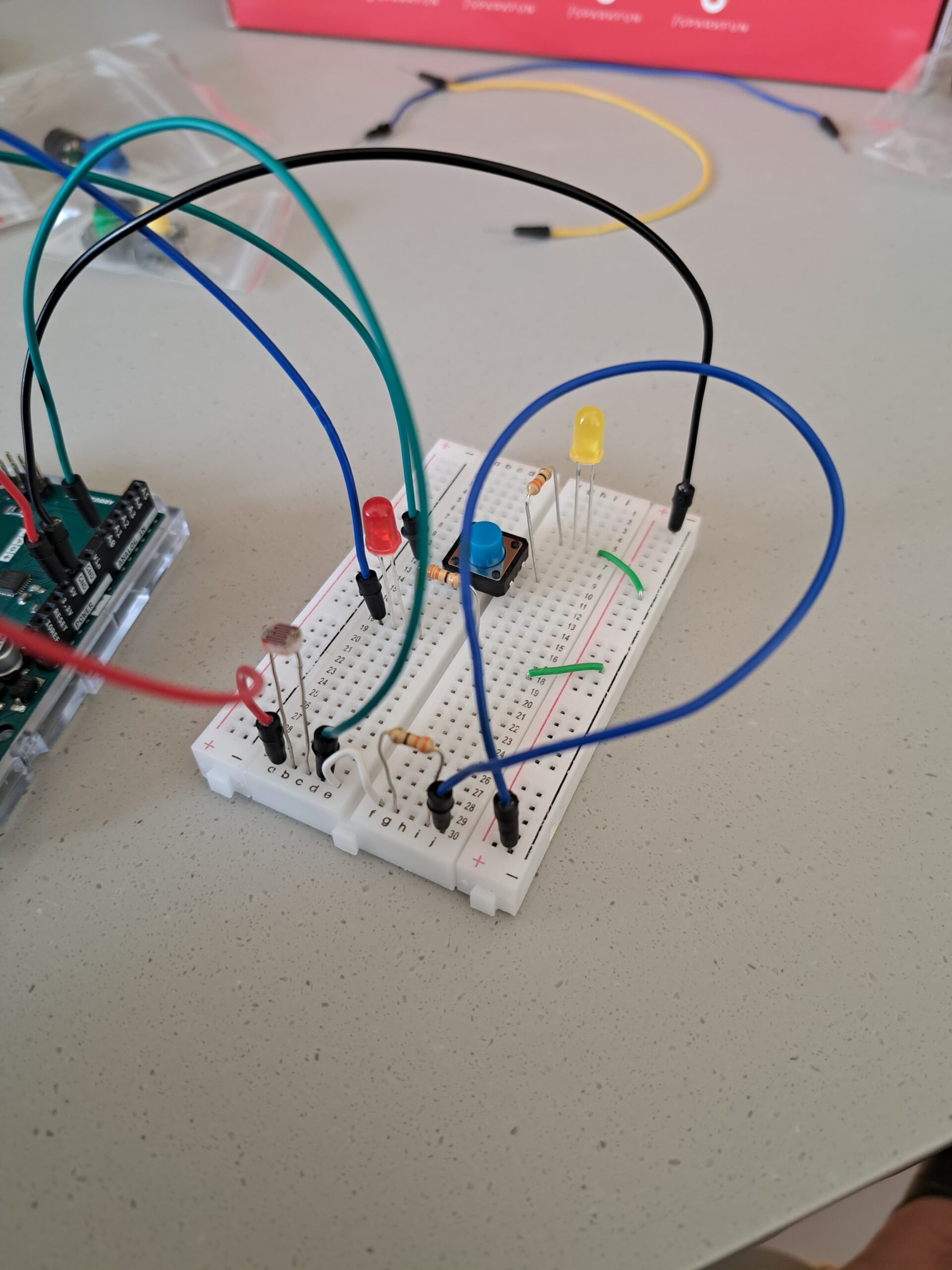
Anyways, I decided I would use this lamp for something other than playing around with its colors. So I made this kind of proximity/light sensor thing. Basically when I hold the lamp close to the the circuit, the red LED turns off and as I back up the lamp, the red LED blinks slower and slower until it stops blinking. As long as the red LED blinks/is on, the green LED can be turned on using a digital switch. Initially while making this circuit, I ran into some very silly difficulties – I attached the components on a single row which meant the circuit was never complete and I couldn’t figure out the problem the entire night for the life of me. Here is the bad circuit:
But one debugging session later here is my creation, the good circuit:
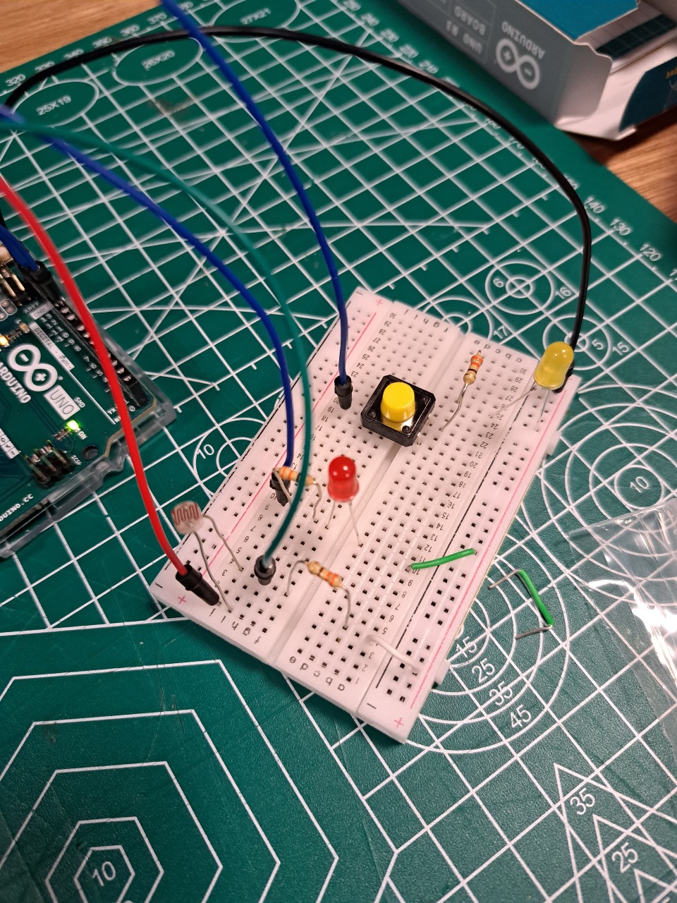
It works in a very fun way and the lamp works in an even fun-er way. Check out the video I’ve attached of the LEDs in action:
https://drive.google.com/drive/folders/1uOQwTJqiPt6b5cQ-L8GTVn3CXHp50x17?usp=sharing
Here is the code:
int green = 10;
int red = 11;
// the setup routine runs once when you press reset:
void setup() {
  // initialize serial communication at 9600 bits per second:
  Serial.begin(9600);
  pinMode(green, OUTPUT);
  pinMode(red, OUTPUT);
}

// the loop routine runs over and over again forever:
void loop() {
  // read the input on analog pin 0:
  int sensorValue = analogRead(A0);
  // print out the value you read:
  Serial.println(sensorValue);
  delay(1);  // delay in between reads for stability

if (sensorValue > 40) { // when far, turn on but don't blink
  digitalWrite(green, LOW);
  digitalWrite(red, LOW);
}
if (sensorValue > 15 && sensorValue <= 40) { // when slightly close, blink slow
  digitalWrite(green, HIGH);
  digitalWrite(red, HIGH);
  delay(100);
  digitalWrite(red, LOW);
  delay(100);
}
if (sensorValue <= 15 && sensorValue > 10) { // when closer, blink fast
  digitalWrite(green, HIGH);
  digitalWrite(red, HIGH);
  delay(250);
  digitalWrite(red, LOW);
  delay(250);
}
if (sensorValue <= 10) { // when very close, turn off
  digitalWrite(green, HIGH);
  digitalWrite(red, HIGH);
}

}
Week 9: Eye Protection
Concept:
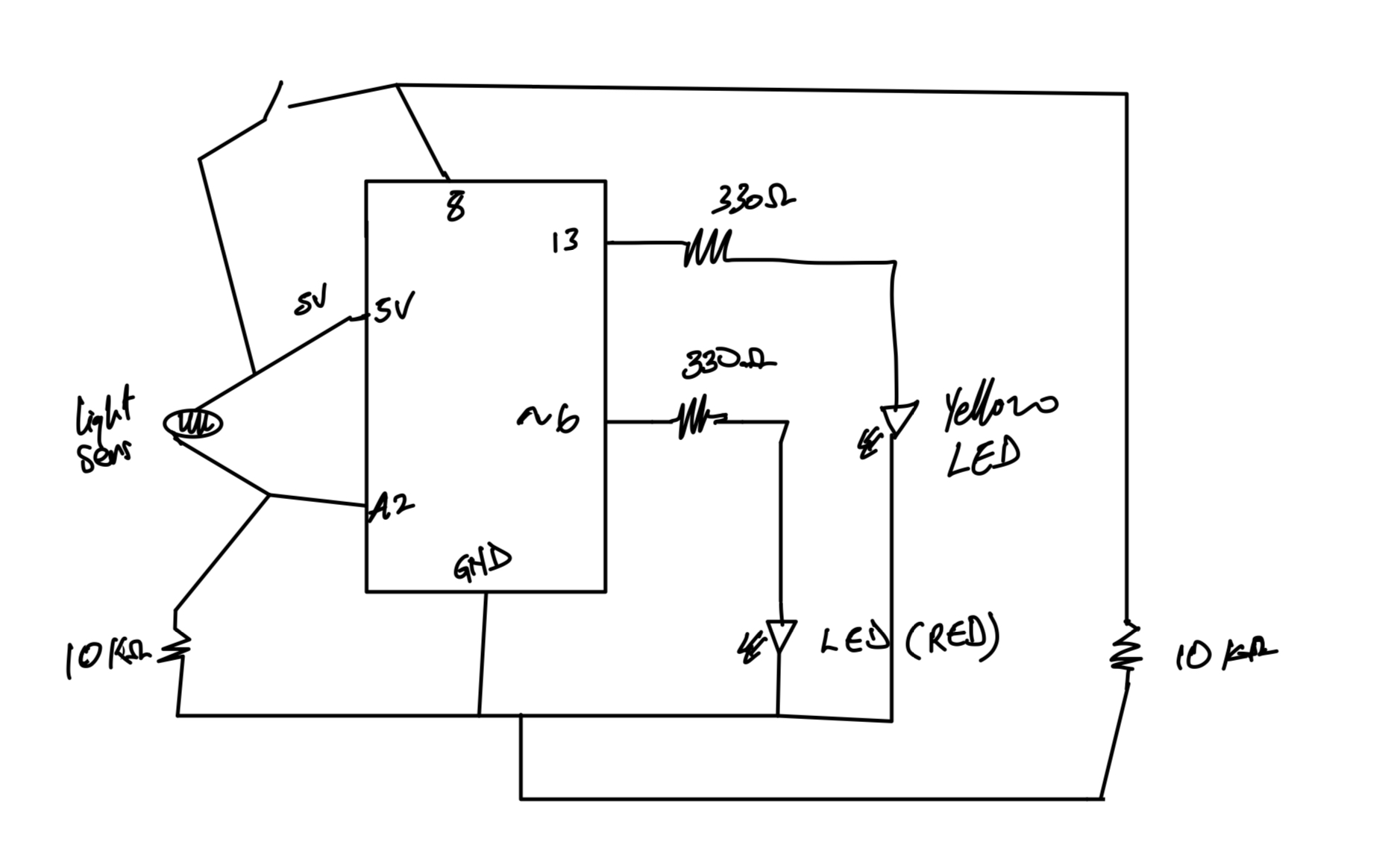
I often use my phone late in the night with my light out and this has been messing up my eyesight for this Project I decided to create a form of eye protection warning system that alerts the user with the use of an LED when the light from their phone screen or laptop is too bright.
So when the screen brightness is low the LED remains off and as the user increases the brightness the LED gets brighter. When the screen brightness reaches a level where the user’s eye is at harm the LED starts to blink and when the brightness gets too high the LED blinks faster.
Code:
int warning=0;//variable to store the warning value used to control blinking and led brightness

void setup() {
  // put your setup code here, to run once:
  pinMode(13,OUTPUT);//set the 13 pin to output type
  pinMode(8,INPUT);//set pin 8 to input type
  pinMode(6,OUTPUT);//set pin 6 to output type
  Serial.begin(9600);//set serial screen for viewing values
}

void loop() {
  // put your main code here, to run repeatedly:
  int anasens=analogRead(A2);//read info from light sensor and store in anasens

  int digsens=digitalRead(8);//read info from switch sensor and store digsens
  Serial.println(anasens);//print anasens on serial board
  anasens=constrain(anasens,100,680);//keep the values between 100 and 680 at all times
  warning=map(anasens,100,680,0,255);//rescale the values from 100 and 680 to 0 and 255

  if(digsens==1){//if the switch is pressed
    digitalWrite(13,1);//turn on yellow LED
  }
  else{//if the switch is not pressed
    digitalWrite(13,0);//turn off LED
  }
  if(warning>200){//if the warning is greater than 200
    analogWrite(6,warning);//turn on red LED based on warning value
    delay(100);//wait for 100 milliseconds
    analogWrite(6,0);//turn off red LED
    delay(100);//wait for 100 milliseconds
  }
  if(warning>100&&warning<200){//the value is between 100 and 200
    analogWrite(6,warning);//turn on red LED based on warning value
    delay(500);//wait for 500 milliseconds
    analogWrite(6,0);//turn off red LED
    delay(500);//wait for 500 milliseconds
  }
  analogWrite(6,warning);//turn on red LED based on warning value
}
Highlight:
This was an interesting assignment. I am happy I was able to do it. What i look forward to is making this a wireless connection as connecting the wires was stressful
Circuit Diagram:
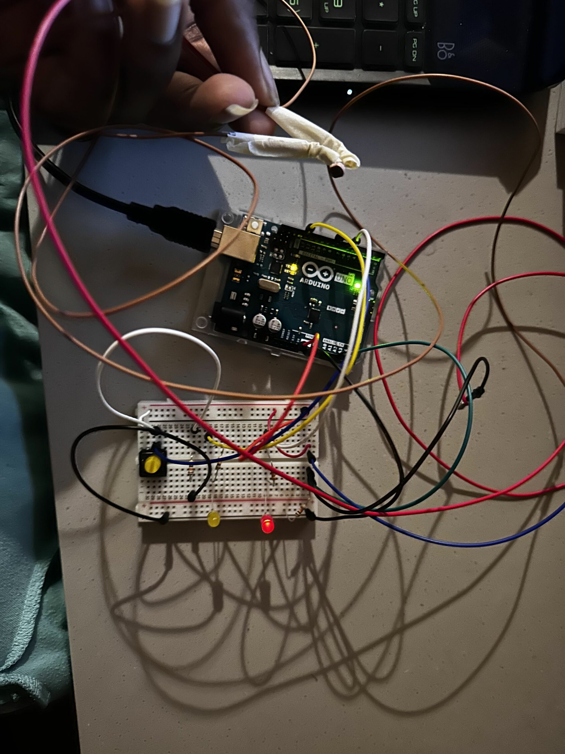
Set-Up Picture:
Video:
https://drive.google.com/drive/folders/17efBVjbUX72MkYQmuw92EqgqJVYxm1Oi?usp=sharing
Thank You!.
Week 9: Are You Alive? (Heat Sensor)
Heat sensor Arduino.
Week 9- Reading Response
In his blog posts, Tom Igoe analyzes the importance of innovative thinking for those who work on physical computing projects and considers the performative dimension of digital products and creative artworks. What strikes me about his approach is that Igoe encourages students to stop thinking of specific ideas as not original and consider how to create variations of them instead. While dance floor pads, electronic instruments controlled by players’ gestures, and touch kiosks may seem overused, such projects bring about a wealth of learning opportunities. Interactive art projects enable creators to engage their audience and discover new interpretations.
Instead of scripting users’ actions, creators should prioritize giving them the freedom to express themselves through works of art. I find this strategy especially useful for product developers, artists, and creative professionals looking for ways to grab the interest of their audience. As it is impossible to predict how a target user may react to an end product without conducting thorough research, we can test out physical computing and creative art projects in real time to get feedback. I think that by analyzing users’ and viewers’ reactions, web developers and artists can increase the value of their projects.
Feeling Snackish
This week’s assignment drew inspiration from a familiar scenario: those late-night kitchen escapades for sneaky snacks. At home, the kitchen lights, being downlighters, don’t just instantly switch on. Instead, there’s a gradual shift when we turn the knob. This unique characteristic prompted me to recreate this experience in my circuit. The analog representation was brought to life through the potentiometer, mirroring the gradual adjustment of the kitchen lights, while the digital side found expression in the toggle switch.
To bring my circuit to life, I gathered a few key components: a potentiometer, a toggle switch, jumper cables, two 10k ohm resistors, one 330-ohm resistor, and two LEDs. The interplay of these elements resulted in the creation of a circuit, visually captured in the image below.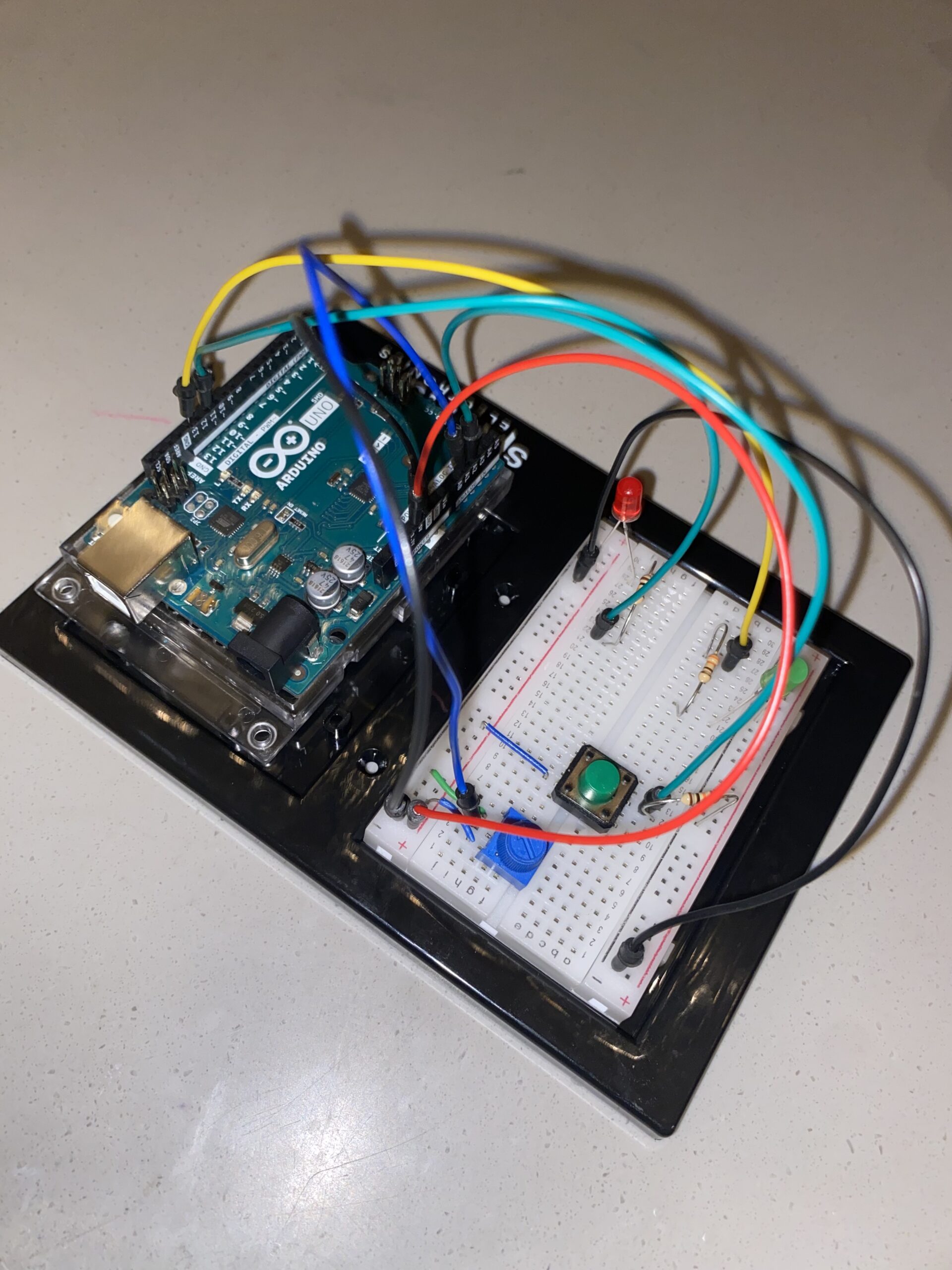
In the process of setting up the circuit, I encountered challenges associated with ensuring the correct placement of components, whether they operated in the digital or analog realm. Despite these hurdles, I noticed a significant improvement in my ability to assemble the circuit compared to my initial attempts. This project underscored the importance of understanding the specific pins corresponding to digital and analog features on the Arduino Uno board. Aligning the code with the appropriate pin modes became crucial for a seamless execution.
Here’s a snippet of the code that brought my project to life:
void loop() {
  int sensorValue= analogRead(A1);
  int buttonState = digitalRead(A2);
  Serial.println(sensorValue);


 analogWrite(led, sensorValue/4);

 delay(30);

 if (buttonState == LOW) {

digitalWrite(13, LOW);

} else {

digitalWrite(13, HIGH);

}
}
Below is the video representation of my assignment.
Reflecting on the project, I recognize its conceptual completeness, yet I aspire to enhance its creative aspect. While the current iteration captures the assignment’s essence, I envision experimenting with diverse LED blinking patterns, moving beyond the conventional blink. Additionally, exploring the possibility of using the potentiometer to control multiple LEDs could add a layer of complexity and creativity to the project, elevating it beyond its current simplicity.
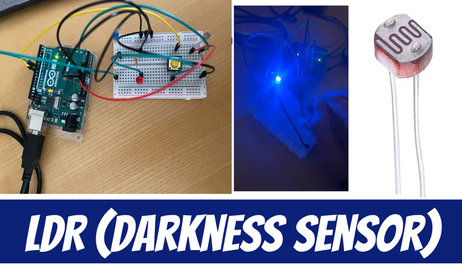
Luminar: Arduino-LDR LED System
Concept
In the realm of electronics, my pursuit led me to create an LDR-controlled LED system using Arduino. The concept is rooted in a personal connection—recalling my younger self’s dependence on a night light for a good night’s sleep. This assignment aims to offer a modern solution by integrating an LDR-controlled LED system, bridging the gap between past comforts and present technology.
Required Hardware
• Arduino UNO
• Light sensor
• LED’s
• Resistor (330 ohms)
• Jumper wires
• Breadboard
• USB cable
• Computer with Arduino IDE installed
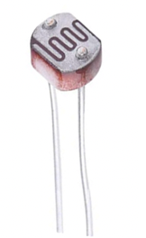
Light Sensor
Circuit Diagram
The circuit diagram was created using Tinker CAD and includes the Light sensor, LED’s, resistor, Arduino UNO, and breadboard.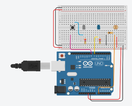
Setting Up the Components
The first step was assembling the components. The LDR was connected to the analog pin A0 on the Arduino, and a resistor was added to create a voltage divider for accurate readings. One LED was directly connected to pin 7, while the second LED was attached to pin 8 through a push button.
Coding the Logic
The Arduino code was crafted to read the analog value from the LDR and determine whether the ambient light was above or below a predefined threshold. If the light level fell below the threshold, both LEDs would illuminate, creating an aesthetically pleasing effect.
int ldrPin = A0;
int led1 = 7;
int led2 = 8;  // New LED pin
int threshold = 70;

void setup()
{
  Serial.begin(9600);
  pinMode(led1, OUTPUT);
  pinMode(led2, OUTPUT);  // Set the new LED pin as OUTPUT
}

void loop()
{
  int data = analogRead(ldrPin);
  Serial.println("");
  Serial.print("Light Sensor ");
  Serial.print("Value = ");
  Serial.print(data);

  if (data <= threshold)
  {
    digitalWrite(led1, HIGH);
    digitalWrite(led2, HIGH);  // Turn on the second LED
  }
  else
  {
    digitalWrite(led1, LOW);
    digitalWrite(led2, LOW);  // Turn off the second LED
  }
}
Hardware Implementation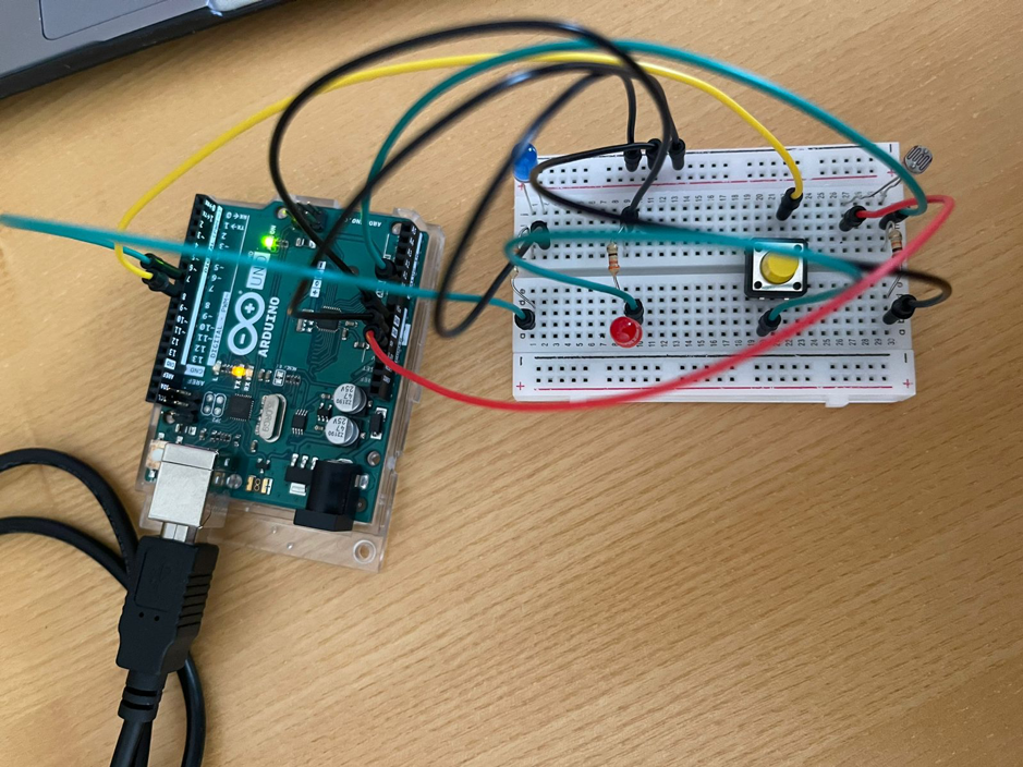
Video Illustration
Working Explanation and Conclusion:
Experimenting using electronics enables the combination of technology and creativity. With this assignment, I investigated the dynamic control of two LEDs using an Arduino, an LDR, and a button. This is an example of the limitless possibilities that exist when imagination and technology are combined, whether it is used as an instructional tool or as a decorative lighting solution. Also, it can be used as a dark sensor if anyone want to sleep in a very light like small bulb.