Reading Reflection – Week #11

Design Meets Disability

While reading the chapter from Graham Pullin’s book, I caught myself thinking about a recent case from my friend’s life – she is a student at Tandon, working on a project in collaboration with Langone Hospital. The theme of the project is development of products for accessible environment, specifically a belt that allows people with blindness to orient in space. My friend’s immediate suggestion was to move the sensors from the belt to hands, e.g. to gloves, so that calculation of the distance to objects was more precise – makes sense, right? However, her idea was met with criticism from the professor – she forgot about that very discretion.

Our goal is to make sure that their limitation not only does not interfere with their lives, but also remains absolutely unnoticeable” – although I do understand the point of my friend’s professor, I would formulate this objective differently. From my understanding, discretion is not simply about hiding the product, but rather about its seamless integration into one’s life. Balancing both engineering and design aspects in one person’s mind is extremely complicated, since the “perfect” solutions in both categories of tasks can be mutually exclusive.

As a person who wears glasses and contacts, used to wear braces and orthopaedic insoles, I have been concerned with the image of such products since I was a child – when I was five, I refused to wear Birkenstock sandals because I was convinced that they were ugly, even though they were prescribed to me by a doctor. That fear of looking stupid and funny is relatable to many people, so I believe that there is a huge room for improvement in the field of design for disability.

Week 11 Assignment

EXERCISE 01: ARDUINO TO P5 COMMUNICATION

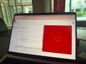
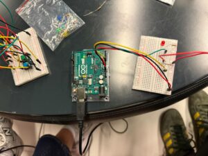
Make something that uses only one sensor on Arduino and makes the ellipse in p5 move on the horizontal axis, in the middle of the screen, and nothing on Arduino is controlled by p5.

P5 code: https://editor.p5js.org/lj2369/full/dO1bxX9t_

let ellipseX = 0; //x value of ellipse to be changed by potentiometer
let B =0;

function setup() {
  createCanvas(640, 480);
  ellipseMode(CENTER);
}

function draw() {
  clear();
  background(0)
  fill(255,0,B);
  ellipse(ellipseX, height/2, 50, 50);


  if (!serialActive) {
    text("Press Space Bar to select Serial Port", 20, 30);
  } else {
    text("Connected", 20, 30);  
    // Print the current values
    text('ellipseX = ' + str(ellipseX), 20, 50);
  }
}

function keyPressed() {
  if (key == " ") {
   
    setUpSerial(); //establish serial communication
  }
}

function readSerial(data) {  
  if (data) {    //run only if data is received
    data = data.trim(); // Remove any whitespace
    if (!isNaN(data)) { //check whether data is a number or not
      //debug: console.log("Received:", data);
      ellipseX = int(data);
    }
  }
}

the location of the x of ellipse is being altered by the potentiometer

Arduino ide: https://github.com/lonussss/Intro-to-IM/blob/main/week11exercise1.ino 


int sensor = A0; 

void setup() {

  Serial.begin(9600);


}

void loop() {
      int sensorValue= analogRead(sensor);
      int mappedValue = map(sensorValue,0,1023,0,640); //mapped value to size of canvas
      Serial.println(mappedValue); //send value to p5.js
  }

The value from the potentiometer is mapped between 0 and 640, the width of the canvas.

Utilizing a Potentiometer, the ellipse moves along the horizontal axis, while also changing colors by making changes to the B value of fill.


Demonstration:

IMG_3526


EXERCISE 02: P5 TO ARDUINO COMMUNICATION

Make something that controls the LED brightness from p5.

P5 slider to control LED brightness

P5: https://editor.p5js.org/tinganyang/sketches/oFcyYfJaa

let slider;
let brightness = 0;
function setup() {
  createCanvas(400, 400);
  // Create a brightness slider
  slider = createSlider(0, 255, 128);
  slider.position(width/2, height/2);
  slider.style('width', '100px');
}
function draw() {
  background(255);
  if (!serialActive) {
    textAlign(CENTER)
    text("Press Space Bar to select Serial Port", width/2, height/3);
  } else {
    text("Connected", width/2, height/3);
  }
  brightness = slider.value();
}
function keyPressed() {
  if (key == " ") {
    // important to have in order to start the serial connection!!
    setUpSerial();
  }
}
function readSerial(data) {
  console.log(data);
    let dataToSend = brightness + ", \n";
    writeSerial(dataToSend);  
}

A slider is created and data from it is sent to the arduino.

Arduino: https://github.com/Ting-AnYang/Intro-to-IM/blob/ebd695cde4ece4858599434e4cc13a205d2b5aef/Week11%20Exercise%202.ino

const int ledPin = 9;  
void setup() {
  pinMode(ledPin, OUTPUT);
  Serial.begin(9600);
}
void loop() {
  Serial.println("sensor");
  if (Serial.available() > 0) {
    int brightness = Serial.parseInt();
    brightness = constrain(brightness, 0, 255);
    analogWrite(ledPin, brightness);
  }
}

Based on the input from the p5 sketch, the LED’s brightness is adjusted accordingly.

Demonstration:

IMG_8413

EXERCISE 03: BI-DIRECTIONAL COMMUNICATION

Take the gravity wind example and make it so:

every time the ball bounces one led lights up and then turns off,

and you can control the wind from one analog sensor


Using a potentiometer mapped from -2 to 2, when the potentiometer is towards the left, the wind blows towards the left, and vice versa. The LED lights up every time the ball touches the bottom edge of the canvas.

P5: https://editor.p5js.org/lj2369/full/EbBBWKl0S

function draw() {
  background(255);
  applyForce(wind);
  applyForce(gravity);
  velocity.add(acceleration);
  velocity.mult(drag);
  position.add(velocity);
  acceleration.mult(0);
  ellipse(position.x,position.y,mass,mass);
  if (position.y > height-mass/2) {
      velocity.y *= -0.9;  // A little dampening when hitting the bottom
      position.y = height-mass/2;
    
    
    if(serialActive){
      writeSerial("bounced\n");
    }
    }
  // Check for collisions with the left wall
  if (position.x < mass / 2) {
    velocity.x =0; // Reverse horizontal velocity (bounce)
    position.x = mass / 2; // Correct position
  }

  // Check for collisions with the right wall
  if (position.x > width - mass / 2) {
    velocity.x =0; // Reverse horizontal velocity (bounce)
    position.x = width - mass / 2; // Correct position
  }
}

f

function readSerial(data){
  
  if (data != null){
    wind.x=int(data);
    console.log("working");

  }
}

A serial signal is sent to arduino everytime the ball touches the bottom of the canvas, resulting in the led to light up on the arduino. The potentiometer’s value will be reflected in the direction that the wind is blowing on the ball. I also added two walls on the right and left sides of the canvas, to prevent the wind from blowing the ball outside of the canvas.

Arudino: https://github.com/lonussss/Intro-to-IM/blob/main/week11exercise3.ino 


int ledPin = 8;       // Pin connected to the LED
int sensorPin = A0;   // Pin connected to the analog sensor
String inputString = "";  // String to accumulate incoming serial data
bool stringComplete = false; // Flag to check if a full command is received

void setup() {
  pinMode(ledPin, OUTPUT);
  Serial.begin(9600); 
}

void loop() {
  

  while(Serial.available()){
    String bounced = Serial.readStringUntil('\n');  //read serial string until new line
    if(bounced == "bounced"){
      flashLED();
    }
  int sensorValue = analogRead(sensorPin); // Read the analog sensor value
  int mappedValue = map(sensorValue, 0, 1023, -3 ,3);  // Map the sensor value to a range (-3 to 3)
  Serial.println(mappedValue); // Send the mapped value to p5.js
  }


}

void flashLED() {
  digitalWrite(ledPin, HIGH); // Turn LED on
  delay(100);                 // Keep LED on for 100 ms
  digitalWrite(ledPin, LOW);  // Turn LED off
}

There’s a function called flashLED which flashes the led 100ms whenever the ball touches the bottom of the canvas. The potentiometer is mapped between -3, and 3. The input will be reflected on the wind in p5.

Demonstration:

IMG_3537

WEEK 11 – READING

DESIGN MEETS DISABILITY

In my opinion, I can’t help feeling frustrated with how slow the world is to adopt these ideas. Why are we still obsessed with invisibility and blending in when we should be celebrating individuality? Aimee Mullins’ prosthetics are a perfect example. they’re not just tools, they’re empowering, glamorous statements of self-expression. To me, this is where design for disability needs to go, embracing boldness rather than hiding behind outdated notions of what’s “appropriate.” It’s frustrating that hearing aids, for example, are still stuck in a cycle of being made to “disappear” rather than be celebrated, unlike glasses that have evolved into full-blown fashion accessories.

I think the text makes a strong case for simplicity in design, but I also feel like it’s dancing around the bigger issue of why it takes products like Apple’s iPod to show us how simplicity can be revolutionary. Everyday products for people with disabilities shouldn’t just be functional, they should inspire pride. In my opinion, the most significant missed opportunity is the lack of integration between mainstream and disability-focused design. The examples here, like dementia-friendly radios and HearWear, are great, but they’re still treated as niche. We need to stop separating these worlds and start making design inclusive from the start.

Final project concept – Goal rush

Concept

For my final project, I want to create football inspired reaction game in which the player plays the role of a goalkeeper. The idea is to replicate penalty shootouts, where split second decisions determine whether you save the ball or let it hit the net.

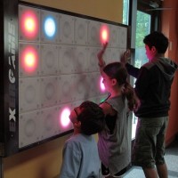
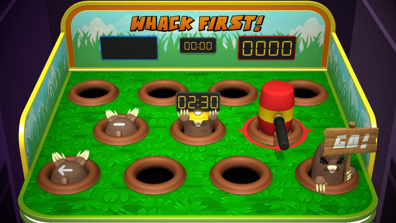
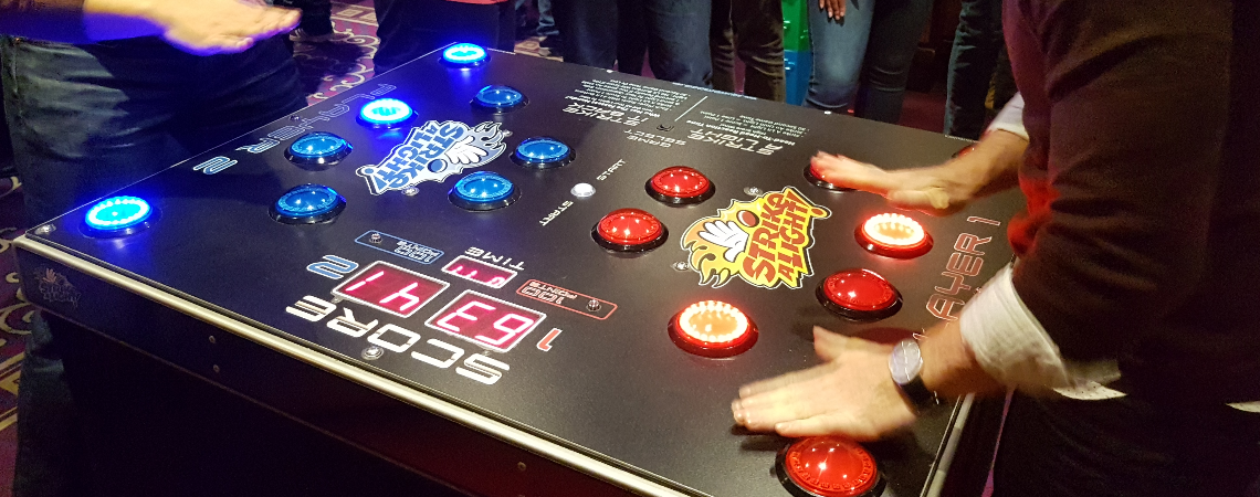
The project draws inspiration from classic arcade games like Whack-a-Mole, where players must react in time to hit the mole. It’s also inspired by the Strike-A-Light reaction game, which emphasizes quick reflexes and precise button presses, and the Interactive T-Wall, which uses a grid-based system to create engaging gameplay. These games inspired me to create something that combines physical action with real-time feedback while adding a personal twist to the football theme.

Wall Active Game « Product categories «
T-WALL
Whack-a-mole - FineProxy Glossary
WHACK A MOLE
Strike a Light - Altitude Events
STRIKE-A-LIGHT

This project is personal because it combines my passion for football with the technical skills I’ve been learning. By adapting the ideas behind arcade games and combining them with the theme of football, I was able to create something exciting and interactive. The result is a challenging and fun game, capturing the essence of football while incorporating creative design and technical elements.

How It Works

In Goal Rush, the physical setup consists of six buttons arranged in a semi-circle, similar to how a ball might travel to different parts of a goalpost during a penalty kick. Above each button is an LED that lights up to signal where the ball is “shot.” The player, acting as the goalkeeper, must press the corresponding button to make the save. If they react quickly enough and press the right button, the Arduino sends a signal to the p5.js display, where the digital goalkeeper dives to block the ball. The ball goes into the net if the player misses or presses the wrong button.

The p5.js display mirrors the physical setup with a goalpost and a goalkeeper. It shows the outcome of each attempt, whether the shot was saved or scored. The game keeps track of the player’s score, rewarding saves and displaying a missed goal animation for failed attempts. The game starts off at a steady speed but becomes faster as it progresses, challenging the player’s reflexes and ability to stay focused.

The objective is to save as many goals as possible before the timer runs out. The combination of tactile button presses and real-time visual feedback creates an experience that captures the tension and excitement of a penalty shootout.

Reading Reflection – Week #11

Design Meets Disability

I always found the medical and disability assistance intended design very hard to work on and hence I never tried to evaluate it on the basis of design or aesthetics, rather than its usability and usefulness. I really liked how author approached the topic, seeing people with disabilities as a specific group of users whose needs and wants are usually not taken into account by the engineers or designers.

I think, like the author said, glasses is a great example of a product, which abandoned the association with disability, since from the moment I started wearing glasses, I never thought of them as a special needs device or assistance (even though they were), rather glasses were like my stylistic choice. When author discussed different cases, the idea of braces came to my mind, since is also became not only the medical tool to correct teeth, but some people are using braces to find a new fashion style for them.

It’s very disappointing to realize that users with disabilities have to compromise between more useful and technological product and product that provides discretion, since apparently those two objectives become conflicting in design. The approach “one fits all” also doesn’t work when we work in inclusivity, even though we seem to target one group – people with disabilities: we must recognize variance in disabilities as well.

In my view, the conviction that accessibility devices should prioritize discretion stemmed from current inability of engineers/designers to produce more confident and accomplished design, which would make users want to be seen.

The chapter introduced me to new concepts, such as appliance and new knowledge about dementia: I wasn’t aware that it is often accompanied by a heightened artistic appreciation and emotional response.

Assignment 9 – Serial Communication

Task 1

Prompt: Make something that uses only one sensor on Arduino and makes the ellipse in p5 move on the horizontal axis, in the middle of the screen, and nothing on Arduino is controlled by p5.

We decided to approach all the tasks following Christmas style.

P5 Code:
let positionX = 0; 

function setup() {
  createCanvas(600, 600);
  noFill();
}

function draw() {
  background("#bb010b");
  stroke("#ffcf00");
  // maping the values from light sensor to the width of the canvas
  ellipse(map(positionX, 0, 1023, 0, width), height / 2, 100, 100);

  if (!serialActive) {
  // the initial screen of p5, when it is not connected to arduino, this helps to start serial communication
    background("#2d661b");
    stroke("#white");
    textSize(50);
    text("Press Space Bar to select Serial Port", 20, 30, width - 30, 200);
  }
}

function keyPressed() {
  // starting serial communication when space bar is pressed
  if (key == " ") setUpSerial(); 
}

function readSerial(data) {
  if (data != null)
    // ensuring there is actual data, then storing it in a variable
    positionX = int(data);
}
Arduino Code
int lightPin = A0;

void setup() {
Serial.begin(9600);
pinMode(lightPin, INPUT);
}

void loop() {
int sensorValue = analogRead(A0);
Serial.println(sensorValue);
delay(5);
}

Task 2

Prompt: Make something that controls the LED brightness from p5

For this assignment, we decided to control LED brightness using 4 circles/buttons on p5 interface. By pressing different circles, you increased the brightness of LED.

P5 Code
let LEDbrightness = 0; 

function setup() {
  createCanvas(600, 600);
  background('#2d661b');
  stroke ('#white');
  noFill();
}

function draw() {
  
  if (serialActive){  
  
  //circles-buttons
  circle (150, height/2, 50);
  circle (250, height/2, 50);
  circle (350, height/2, 50);
  circle (450, height/2, 50);
  
  // to understand whether user pressed specific circles, we used distance function. the LED brightness had 4 variations
  if (dist (mouseX, mouseY, 150, height/2) <= 50){
    LEDbrightness = 60;
  }
  if (dist(mouseX, mouseY, 250, height/2)<=50){
    LEDbrightness = 120;
  }
  if (dist(mouseX, mouseY, 350, height/2)<=50){
    LEDbrightness = 180;
  }
  if (dist(mouseX, mouseY, 450, height/2)<=50){
    LEDbrightness = 255;
  }
    }
  
  if (!serialActive) {
    // to understand if serial communication is happening
    textSize(50);
    text ("Press Space Bar to select Serial Port", 20, 30, width-30, 200);
    }
  }
function keyPressed() {
    if (key == " ")
      // starting the serial connection using space bar press
        setUpSerial(); 
}

function readSerial(data) {
  //sending data to arduino
    writeSerial(LEDbrightness);
}
Arduino Code
void setup() {
Serial.begin(9600);
pinMode(5, OUTPUT);
}

void loop() {
analogWrite(5, Serial.parseInt());
Serial.println();
}

IMG_9258

Task 3

Prompt: Take the gravity wind example and make it so every time the ball bounces one led lights up and then turns off, and you can control the wind from one analog sensor.

We decided to use light sensor as analog sensor, which controlled the wind on p5 that affected movement of ball.

P5 Code
let position, velocity, acceleration, gravity, wind;
let drag = 0.99,
  mass = 50,
  hasBounced = false;

function setup() {
  createCanvas(640, 360);
  noFill();
  position = createVector(width / 2, 0);
  velocity = createVector(0, 0);
  acceleration = createVector(0, 0);
  gravity = createVector(0, 0.5 * mass);
  wind = createVector(0, 0);
  textSize(18);
}

function draw() {
  background(255);

  if (!serialActive) {
    background("#2d661b");
    fill("white");
    text("Press F to select Serial Port", 20, 30, width - 30, 200);
  } else {
    applyForce(wind);
    applyForce(gravity);
    velocity.add(acceleration);
    velocity.mult(drag);
    position.add(velocity);
    acceleration.mult(0);

    if (hasBounced) {
      fill("red");
    } else {
      fill("white");
    }
    ellipse(position.x, position.y, mass, mass);

    if (position.y > height - mass / 2) {
      velocity.y *= -0.9; // dampening
      position.y = height - mass / 2;

      if (!hasBounced && abs(velocity.y) > 1) {
        hasBounced = true;
        setTimeout(() => (hasBounced = false), 100);
      }
    }
  }
}

function applyForce(force) {
  let f = p5.Vector.div(force, mass);
  acceleration.add(f);
}

function keyPressed() {
  if (key == " ") {
    mass = 20;
    position.set(width / 2, -mass);
    velocity.mult(0);
    gravity.y = 0.5 * mass;
    wind.mult(0);
  } else if (key == "f") {
    setUpSerial();
  }
}

function readSerial(data) {
  if (data != null) {
    let value = int(trim(data)); 
    wind.x = map(value, 0, 1023, -1, 1);
    let bounceState = 0;
    if (hasBounced) {
      bounceState = 1;
    }
    writeSerial(bounceState + "\n");
  }
}
Arduino Code
const int ledPin = 5;
const int lightPin = A0;

void setup() {
    Serial.begin(9600);
    pinMode(ledPin, OUTPUT);
    pinMode(lightPin, INPUT);

    while (Serial.available() <= 0) {
        Serial.println("0"); 
;    }
}

void loop() {
    while (Serial.available()) {
        int ledState = Serial.parseInt(); 
        
        if (Serial.read() == '\n') {
            digitalWrite(ledPin, ledState);
            Serial.println(analogRead(lightPin));
        }
    }
}

IMG_9260

Final Project Concept

For my final project, I want to create a  Harry Potter-inspired Magic Wand Simulator. The project would use an infrared (IR) sensor attached to the tip of the wand to detect gestures and proximity, allowing users to perform actions like raising, flicking, or pointing the wand to trigger spells.

Each spell corresponds to specific animations and effects in p5 and provides feedback through physical outputs controlled by Arduino, such as lighting up LEDs or playing sounds. Ideally I would want the motion to be accurate like the films/books. So hopefully the movements will be detected accurately. For example, creating the motion for Lumos, causes the p5 screen to brighten. I plan to create the p5 screen to look like a Hogwarts common room, and be able to move objects, turn the light on/off, etc, based on the wand’s movement.


Week 11 Assignment | Serial Communication Exercise 1-3

Example 1 – Arduino to p5 communication

IMG_3382

P5 code

let X = 0; // ellipse x position


function setup() {
  createCanvas(400, 400); 
}

function draw() {
  background(240); 

  fill('rgb(134,126,126)'); 
  ellipse(X, height/2, 80); 
}

function keyPressed() {
  if (key === " ") {
    setUpSerial(); // Start the serial connection on space bar press
  }
}

// Processes incoming data from Arduino
function readSerial(data) {
  if (data != null) {
    let fromArduino = split(trim(data), ","); // Split incoming data by commas

    if (fromArduino.length >= 1) {
      // Process the first value for X position
      let potValue = int(fromArduino[0]); // Convert string to integer
      X = map(potValue, 0, 1023, 50, width - 50); // Map potentiometer value to X position
      Y = height / 2; // Keep Y position constant
    }
  }
}

Arduino code

void setup() {
  Serial.begin(9600); //  serial communication
}

void loop() {
  int potValue = analogRead(A0); // potentiometer value
  Serial.println(potValue);     // send the value to the serial port
  delay(10);                   
}

Example 2 – P5 to Arduino Communication


p5 code

let brightness = 0; // Brightness value to send to Arduino

function setup() {
  createCanvas(640, 480);
  textSize(18);
}

function draw() {
  background(255);

  if (!serialActive) {
    // If serial is not active display instruction
    text("Press Space Bar to select Serial Port", 20, 30);
  } else {
    // If serial is active, display connection status and brightness value
    text("Connected", 20, 30);
    text('Brightness = ' + str(brightness), 20, 50);
  }

  // Map the mouseX position (0 to width) to brightness (0 to 255)
  brightness = map(mouseX, 0, width, 0, 255);
  brightness = constrain(brightness, 0, 255); // Ensures brightness is within the range 0-255

  // Sends brightness value to Arduino
  sendToArduino(brightness);
}

function keyPressed() {
  if (key == " ") {
    // Start serial connection when the space bar is pressed
    setUpSerial();
  }
}


function readSerial(data) {
  if (data != null) {

  }
}
// We dont need this part of the code because we are not getting any value from the Arduino

// Send brightness value to Arduino
function sendToArduino(value) {
  if (serialActive) {
    let sendToArduino = int(value) + "\n"; // Convert brightness to an integer, add newline
    writeSerial(sendToArduino); // Send the value using the serial library
  }
}

Arduino code

void setup() {
  Serial.begin(9600); //  serial communication
}

void loop() {
  int potValue = analogRead(A0); // potentiometer value
  Serial.println(potValue);     // send the value to the serial port
  delay(10);                   
}

Example 3 – Bi-Directional Communication


p5 code

let velocity;
let gravity;
let position;
let acceleration;
let wind;
let drag = 0.99;
let mass = 50;


let windValue = 0; // Wind value from Arduino (light sensor)
let serialConnected = false; // Tracks if the serial port is selected

function setup() {
  createCanvas(640, 360);
  textSize(18); 
  noFill();

  position = createVector(width / 2, 0);
  velocity = createVector(0, 0);
  acceleration = createVector(0, 0);
  gravity = createVector(0, 0.5 * mass);
  wind = createVector(0, 0);
}

function draw() {
  background(255);

  if (!serialConnected) {
    // Show instructions to connect serial port
    textAlign(CENTER, CENTER);
    fill(0); // Black text
    text("Press Space Bar to select Serial Port", width / 2, height / 2);
    return; // Stop loop until the serial port is selected
  } else if (!serialActive) {
    // Show connection status while waiting for serial to activate
    textAlign(CENTER, CENTER);
    fill(0);
    text("Connecting to Serial Port...", width / 2, height / 2);
    return; // Stop until the serial connection is active
  } else {
    // display wind value and start the simulation if connected
    textAlign(LEFT, TOP);
    fill(0);
    text("Connected", 20, 30);
    text('Wind Value: ' + windValue, 20, 50);
  }

  // Apply forces to the ball
  applyForce(wind);
  applyForce(gravity);

  // Update motion
  velocity.add(acceleration);
  velocity.mult(drag);
  position.add(velocity);
  acceleration.mult(0);

  // Draw the ball
  ellipse(position.x, position.y, mass, mass);

  // Check for bounce
  if (position.y > height - mass / 2) {
    velocity.y *= -0.9; 
    position.y = height - mass / 2; // Keep the ball on top of the floor 

    // Sends signal to Arduino about the bounce
    sendBounceSignal();
  }

  // Update wind force based on Arduino input
  wind.x = map(windValue, 0, 1023, -1, 1); // Map sensor value to wind range
}

function applyForce(force) {
  let f = p5.Vector.div(force, mass);// Force divided by mass gives acceleration
  acceleration.add(f);
}

// Send a bounce signal to Arduino
function sendBounceSignal() {
  if (serialActive) {
    let sendToArduino = "1\n"; // Signal Arduino with "1" for a bounce
    writeSerial(sendToArduino);
  }
}

// incoming serial data from Arduino
function readSerial(data) {
  if (data != null) {
    windValue = int(trim(data)); // store the wind value
  }
}

// Press space bar to initialize serial connection
function keyPressed() {
  if (key == " ") {
    setUpSerial(); // Initialize the serial connection
    serialConnected = true; // Mark the serial port as selected
  }
}

// Callback when serial port is successfully opened
function serialOpened() {
  serialActive = true; // Mark the connection as active
}

Arduino code

const int ledPin = 9;  // Digital pin 9 connected to the LED
const int lightSensor = A0; // Analog input pin A0 for the light sensor

void setup() {
  Serial.begin(9600);      // Start serial communication
  pinMode(ledPin, OUTPUT); // Set LED pin as an output
}

void loop() {
  // Read the light sensor value
  int lightValue = analogRead(lightSensor);

  // Send the light value to p5.js
  Serial.println(lightValue);

  // Check for bounce signal (when ball touches the ground) from p5.js
  if (Serial.available() > 0) {
    int bounceSignal = Serial.parseInt();
    if (Serial.read() == '\n' && bounceSignal == 1) {
      // Turn on the LED briefly to indicate a bounce
      digitalWrite(ledPin, HIGH);
      delay(100);
      digitalWrite(ledPin, LOW);
    }
  }

  delay(50); // Small delay 
}


Final Project Idea

For my final project, I’m creating a music learning device to help kids read beginner music notes in a fun and interactive way. The device will have an LED button panel with nine buttons, each representing a specific musical note on the staff. These buttons will cover notes on both the lines and spaces, making it easy for kids to learn where each note is positioned.

I’ll start with a tutorial to introduce the notes, showing their names and positions on a staff while the matching LED button lights up. This way, kids can visually connect each note’s name with its place.

After the tutorial, there’s a gameplay mode to reinforce what they’ve learned. Notes will appear on a screen, and the player needs to press the corresponding LED button as fast as they can. They’ll earn points for correct answers and lose points for wrong ones, with the goal of getting as many points as possible in 90 seconds. This competitive element makes learning both challenging and enjoyable.

The device will use serial communication between an Arduino and p5.js. The Arduino will handle the LEDs and buttons, while p5.js will display notes on the screen and manage the game logic, like scoring and timing. This setup will create a smooth connection between what’s happening on screen and the physical buttons.

To make the learning even more immersive, there will be sounds for each note. A potentiometer will be included to allow the user to adjust the volume of the sound, giving them control over how loud or soft they want the feedback to be. When a button is pressed, the corresponding musical tone will play, helping kids connect the note visually.

Reading Response 8

In “Design Meets Disability,” the author talks about how design and disability come together in ways we don’t usually think about. He challenges the idea that things made for people with disabilities shouldn’t only be practical. Instead, they can be beautiful and a way for someone to express who they are. I found this really interesting, especially when the author compared eyeglasses, which are now a fashion accessory, with hearing aids, which are often hidden. It made me realize how much society’s views affect the way these tools are designed.

I really liked how the author said that designers should do more than just try to “fix” disabilities. They should make products that celebrate differences. It made me think about what good design really means. Shouldn’t it be about helping people feel empowered and giving them choices? For example, think about how wheelchairs have changed over time. Old wheelchairs were bulky and just focused on function. But now, there are wheelchairs that are lightweight, stylish, and customizable. They give people more than just mobility, they help them feel confident. This is exactly the kind of change the author is talking about.

Another example is prosthetic limbs. In the past, they were designed to blend in and look as “natural” as possible. But now, some prosthetics are colorful and artistic, or they look futuristic, like the bionic limbs. These designs are more than just tools, they let people show their personality and feel proud of what they’re wearing.

The book left me feeling hopeful about what could happen if more designers thought this way. Assistive devices could become something people actually want to use, not just something they need. Imagine a future where these devices are seen as an exciting part of someone’s personality, like how clothes or accessories are today.

Overall, I appreciated the author’s perspective. It added a lot to the conversation about inclusion and made me see how much potential there is in rethinking assistive design as something not just useful, but also appealing.