Week 9 – Dynamic Light Play

Dynamic Light Play: Interactive LED Control with Potentiometer and Button

Concept

The aim of this project was to use a combination of analog and digital inputs to control two LEDs (one red, one blue) in a creative and functional way. The potentiometer serves as an analog input, allowing us to control the brightness of the red LED, while a button acts as a digital input to control the blue LED. This setup meets the assignment requirement to use at least one analog sensor and one digital sensor, with one LED controlled in an analog fashion and the other in a digital fashion.

Materials Used

  • Arduino Uno board
  • Breadboard
  • Red LED and Blue LED
  • Potentiometer (analog sensor)
  • Button (digital sensor)
  • Resistors:
    • 10kΩ for the button’s pull-up resistor
    • 330Ω for each LED
  • Jumper Wires

Arduino Code


const int potPin = A0;       
const int buttonPin = 2;    
const int redLEDPin = 9;     
const int blueLEDPin = 8;    

void setup() {
  pinMode(buttonPin, INPUT_PULLUP); 
  pinMode(redLEDPin, OUTPUT);       
  pinMode(blueLEDPin, OUTPUT);      
}

void loop() {
  
  int potValue = analogRead(potPin);

  
  int redLEDIntensity = map(potValue, 0, 1023, 0, 255);

 
  analogWrite(redLEDPin, redLEDIntensity);

  
  int buttonState = digitalRead(buttonPin);

  
  if (buttonState == LOW) {
    digitalWrite(blueLEDPin, HIGH);  
  } else {
    digitalWrite(blueLEDPin, LOW);   
  }

  
  delay(10);
}

Implementation

Video Demonstration

IMG_3370

Reflections

This project was a practical way to understand the difference between analog and digital inputs and outputs. The potentiometer provided smooth, gradual control over the brightness of the red LED, giving me hands-on experience with analog input. The button provided simple on/off control for the blue LED, demonstrating digital input.

Challenges:

  • Button Debouncing: Without the slight delay, the button would sometimes register multiple presses in a quick succession due to “bouncing.” Adding a delay(10); solved this issue.

Future Improvements:

  • Adding more LEDs or sensors to expand the circuit’s functionality.
  • Using more advanced analog sensors, such as a temperature or light sensor, to explore other applications.

Week 9: Smiley Sensors

Concept 

For this week’s project I decided to create a smiley face out of LEDs and use different sensors & switches to control different color LEDs. Conceptually, this idea is fairly simple. When I read the assignment I almost immediately knew that I wanted to do a smiley face and just had to figure out how I would incorporate the different switches in an interesting way. When I looked online I was also pleased to see that there weren’t many renditions of my idea so I felt like I had to think for myself (at least to some extent). However, I did see the use of a LED screen (not included in our Arduino kits) that I would be interested in exploring in future projects.

Final Project & Schematic 

Design

Like I mentioned before, my design is pretty simple. I am using blue and yellow alternating LED lights to illuminate a smiley face. The brightness of the blue LED’s is controlled using the potentiometer and then the yellow LEDs are illuminated using the manual switch. I enjoyed this project a lot because it really tested my knowledge of what we’ve learned in class over the last two weeks. Although it is basically what we’ve done in class just on a slightly more complicated scale, I found that introducing more components made it much more difficult to manage the information and connect pieces accordingly.

One aspect I am proud of is the simplicity of the code. In order to get this to work I only needed to implement the potentiometer code from class and have the manual switch functioning just off of power. Although this seems like common sense (since the switch connects the current itself) I had to go through a trial and error to realize the code I was trying to implement (a merge between the code for switches and the potentiometer) was virtually pointless.

Future Recommendations

In the future I would really like to improve this project by simplifying it. I originally tried to connect everything using resistors but due to other issues in my circuit ended up restarting and only using wires. Although for the sake of this assignment I didn’t really mind, the amount of wires definitely takes away for the “art” itself. I’m sure there a multiple ways I can simplify my circuit or use other materials just to minimize the “under construction” appearance it currently has. Other than that, I am fairly satisfied with the outcome and am excited to apply these techniques to more complicate future tasks.

Week 9 – Reading Response

Okay, we should have read these earlier, I guess. Rather than discovering now things (well, there are a few in the physical computing list), I would say that reading these two passages was like reacquainting myself with some of my takeaways from the first half of our course.

‘Shut up’ is a rude phrase, especially when it’s called to the alleged ‘creator’ of a piece – I thought. Then it comes to the question again: “To what extent could we deem to be the creator, and to what extent should the intentionalistic pursuit of the creator be respected?” I have no clear answer to this. But if we hop out of the framework of intentionalism and think of ‘shut up’ as also a part of the ‘creation’ process—as if there is no static ‘art piece’ but only the rating process (borrowed from musicking if you’re curious), then the seeming sacrifice of intentionalism could serve something higher than itself. Philosophical enough, even merely regarding the pragmatic effect that ‘shut up’ could bring us, I believe the amusing moments that happened in our mid-term presentation could speak for themselves, signaling us creators to take another lens and subsequently improve the creation. That is, in a sense, also the creation process, isn’t it?

Anyway, as for the topics/types of physical computing projects listed, obviously, just within our class (or even only within my projects), there are already a lot of ‘overlapping’ ideas. If you ask me if in this particular case I would be bothered by the ‘ingenuity’, the answer – surprising or not – would be a clear NO. My interpretation of this problem would be similar to cover versions of music and the iteratively performed classical music – each and every version/performance contributes to the collective musicking process with its own uniqueness. Even if we are ‘just copying’, there is still nothing to be ashamed of: copying, or more professionally speaking, imitating, is still one of the best ways to learn.

Week 9: Digital/ Analog Input & Output

Overview Video Link

The production goal for this week was to understand and play with the analog and digital components in the kit. Then with the input of the components, apply the readings to at least two LED bulbs. Just for fun, I decided to use 4 because I wanted them to glow in a random pattern with varying brightness. With the potentiometer, I decided to showcase how it can be linked to multiple LEDs to control their brightness.

Difficulty and Success of the Process

I felt the most difficult part of the process was the coding and software. Alongside getting use to the IDE, I think connecting the wires to the correct input ports and then referencing the port in the code was a bit confusing to me. Since some of the input ports on the Arduino do not have Pulse Width Modulation (PWM) that converts digital inputs into analog results, I initially was connecting leads to port 13 that didn’t have PWM functionality resulting in my LED blinking when I didn’t want them to and other fault design. With a quick Google search, it seemed like pins 3,5,6,9,10,11 have PWM functionality and changing my routing to those pins resolved most of my issues. As such, my recommendation for others starting out is to use those pins when working with analog measurements while using digital components.

On the other hand, I found great success in connecting multiple LEDs on my breadboard and then connecting the various parts in the IDE. I had a lot of fun organizing and visualizing the routing and see how each of the components would work together. I really loved how the random pattern turned out, but I think in the future I would like to find a way to connect the brightness control with the pattern. With the potentiometer, I ended up connecting each individual light with the meter, but not when the pattern was being displayed. I also wished I had more buttons to play around as well. However, I am still happy with the overall design and look forward to future projects.

Schematic (TinkerCAD)

IRL Photo


Week 9 – Production Post

Idea

For this assignment, I came up with a simple idea of creating a personal space invasion detector. The circuit has two mode, turned on and off using digital input (switch), the space detection using analog input (photoresistor). If the hand comes to close the person, the yellow light will dim. I use the yellow LED because it normally symbolizes happiness, which means when it dims, the person becomes less happy because someone invaded his personal space.

Implementation

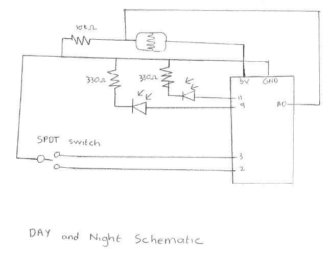
I drew a circuit of the detector, including 2 LEDs, 1 photoresistor, 1 resistor and 1 switch. The switch I use is the rectangular one with three connecting points. If points 1-2 are connected, turn on the red LED, if 2-3 are connected, turn on yellow LED (connected to photoresistor).

Video

Week 9 – Sunfbot

intro

Again, identifying the challenging aspect of the mission seemed the very first step I would take in approaching a new product. This time, while digitally/analog-ly reading/writing can be achieved easily, finding the right connection between the readings and the writings—in terms of both values and functions is what I’d like to focus on. As I found the light sensor we tried in class interesting enough, I came up with this product by combining the light sensors and a servo.

process

Although theoretically, maybe we should have a clear picture of the final product before getting our hands dirty (and I thought I had), sometimes it did take time to distinguish between ‘think of a function’ and ‘think of a product.’ In the first stage of my development, the ‘rotating to follow the light source’ function was already achieved, while the ‘product’ had only the electronics exposed blatantly:

Later on, the very simple concept of a sunflower following the sun finally popped up in my mind. With one piece of cardboard added to the product, although the concept may seem simpler than ‘Dual Light Sensor Servo Control,’ the gist is much more directly conveyed, I believe. On top of that, the additional layer of cardboard actually brought the bonus of normalizing the light sensors physically by shielding out the ambient light:

schematics & illustration

Both of the graphs are drawn and generated with TinkerCAD

Code

The servo rotation is based on the difference between the readings of the two light sensors:

/* 
‘Sunfbot’
Dual Light Sensor Servo Control
This program controls a servo motor based on the difference between two light sensors.
The servo moves to track the stronger light source.

Components:
- 2x LDR (Light Dependent Resistors)
- 2x 10kΩ resistors for LDRs
- 2x 3300Ω resistors for LEDs
- 1x Switch
- 1x 9g Servo
- 1x Blue LED
- 1x Green LED


reference:
https://www.arduino.cc/en/Tutorial/BuiltInExamples/AnalogReadSerial
https://www.arduino.cc/en/Tutorial/LibraryExamples/Sweep
*/

#include <Servo.h>

// Pin definitions
#define SWITCH_PIN 2      // Toggle switch input pin
#define SERVO_PIN 9       // Servo control pin
#define BLUE_LED_PIN 10   // Blue LED pin (standby indicator)
#define GREEN_LED_PIN 11  // Green LED pin (running indicator)
#define SENSOR1_PIN A2    // First light sensor
#define SENSOR2_PIN A3    // Second light sensor

// Constants
#define SENSOR_THRESHOLD 30  // Minimum difference between sensors to trigger movement
#define SERVO_DELAY 30       // Delay between servo movements (ms)
#define SENSOR2_OFFSET 30    // Calibration offset for sensor 2

Servo myservo;  // create servo object
int pos = 90;    // variable to store servo position

void setup() {
  // Initialize serial communication
  Serial.begin(9600);
  
  // Initialize servo
  myservo.attach(SERVO_PIN);
  
  // Configure pins
  pinMode(SWITCH_PIN, INPUT_PULLUP);
  pinMode(BLUE_LED_PIN, OUTPUT);
  pinMode(GREEN_LED_PIN, OUTPUT);
}

void loop() {
  // Read sensors
  int sensor1Value = analogRead(SENSOR1_PIN);
  int sensor2Value = analogRead(SENSOR2_PIN);
  int sensorOffset;

  // Read switch state
  int switchState = digitalRead(SWITCH_PIN);
  
  if (switchState == LOW) {  // System active (switch pressed)
    // Update status LEDs
    digitalWrite(GREEN_LED_PIN, HIGH);
    digitalWrite(BLUE_LED_PIN, LOW);

    // Apply sensor calibration
    sensor2Value -= SENSOR2_OFFSET;
    
    // Check if right sensor is significantly brighter
    if ((sensor2Value - sensor1Value) > SENSOR_THRESHOLD) {
      if (pos < 180) {
        pos++;
        myservo.write(pos);
      }
    } 
    // Check if left sensor is significantly brighter
    else if ((sensor1Value - sensor2Value) > SENSOR_THRESHOLD) {
      if (pos > 0) {
        pos--;
        myservo.write(pos);
      }
    }
    // If difference is below threshold, maintain position
    myservo.write(pos);
    delay(SERVO_DELAY);
    
  } else {  // System in standby (switch released)
    // Update status LEDs
    digitalWrite(GREEN_LED_PIN, LOW);
    digitalWrite(BLUE_LED_PIN, HIGH);
    
    // Return to center position
    myservo.write(90);
  }

  // Debug output
  String message = String(sensor1Value) + " " + 
                  String(sensor2Value) + " " + 
                  String(switchState) + " " + 
                  String(abs(sensor1Value - sensor2Value));
  Serial.println(message);
}

Hindsight

Cardboard Gang YES. While I thought I could use the laser cutter to prepare the parts of this product, it turned out that cardboard allowed the product to be finished on time. It’s still true that laser-cut acrylic may look nicer, but it surely should only be introduced when things are settled.

Week 9 Reading Response Post

Physical Computing’s Greatest Hits (and misses)

Tigoe’s Physical Computing’s explores common trends on themes found in physical computing along with their pros and cons. Ranging from implementing toys as touch sensors to using our voice to complete a task, the author emphasizes the versatility we have when it comes to designing our projects. This is particularly interesting because it reminds us how endless our creativity can go as we take mundane, everyday tools and make them into something so much greater. I find this to be particularly applicable in our case because as we make the transition from software based development to hardware, a new creativity block can be formed. In other words, working with physical materials takes an entirely new level of creativity and out of the box thinking as we turn our ideas into reality. The formal introduction of these themes or common trends not only gives us an idea for how we can implement these kind of tools, but also a starting platform of ideas for us to further develop.

Making Interactive Art: Set the Stage, Then Shut Up and Listen

In this article the author starts off by establishing the common, ineffective scenario in which an artist has to walk their audience through every stage of the their creation in order for them to follow what is happening. He highlights this as one of the most important issues to be addressed because of how it heavily hinders the experience of interactive media and art. Tigoe also states that similar to traditional art, viewers deserve the chance to interpret the art on their own and strike up conversations in regards to what it means to them. I find this advice to be extremely helpful because it reminds me of the piece we read early in the semester that said interactive media should think, listen, and speak on its own. In combining these two pieces we can clearly see what makes a strong interactive piece of art and going forward I will use these standards to assess my own work for creativity, originality, and usefulness.

Reading Reflection – Week 9

Physical Computing’s Greatest Hits (and misses)

I really liked the idea that you should not give up on your idea, even if it was already implemented. Instead, if you actually have thoughts on how this particular idea can be improved, it is definitely worth trying to implement it. We are all different in our own ways, so one can come up with something new that the other people did not even think about. There is always room for uniqueness, and if we will stop thinking about something that was done by other people, and rather focus on our imagination and unconventional perspective, we can achieve extraordinary things. This applies not only to the art field but also to life in general.

Other than the author’s idea, I quite enjoyed reading about the examples that he gave. I have seen or at least thought of many of the devices that are mentioned, but I am 100% sure that each of them can be enhanced in one way or another. Looking through some of them in particular, I noticed how people’s imagination can turn into something interesting and original. Some of the works that I liked the most are Troll Mirror and Hourglass Mirror by Daniel Rozin.

Making Interactive Art: Set the Stage, Then Shut Up and Listen

I fully agree with the author’s ideas in this reading. First of all, I really liked the line drawn between interactive artwork and ‘conventional’ art like sculpture and painting. It brings me back to the previous readings about interactivity and what is important to keep in mind while designing it. A user should be able to intuitively catch the idea of what to do without explanations needed. Secondly, I liked the comparison between the director and the artists. You do not want to ‘label’ your interactive artwork by imposing/prompting your idea to the people. They need to reflect on your artwork from their own perspective, which can potentially bring deeper understanding and open unique angles of interpretation of the idea, helping you to work on future improvements of the artwork.

I now understand why the professor did not allow us to describe or explain our midterm projects during the showcase. It was actually quite useful to see and hear (shut up and listen) authentic reactions and feedback from my classmates. It helped me understand which sides of my work I would need to improve in the future to ease the interaction and perception.

Analog input & output – Antiprocrastination Iphone Case 2.0

For this assignment, I decided to release an update for the Antiprocrastination Iphone Case as I promised in my last week blogpost.

Concept

The shortage of the conductive fabric (could not find it in the IM Lab where it was supposed to be) made me find a new way to track the presense of the phone on the surface. This time, I used the conductive tape, which was not that convenient to use, but I experimented with a normal tape to attach it to the phone case and put together the wires.

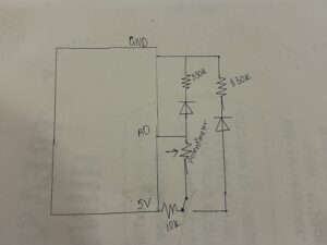
For my analog input, I decided to use the potentiometer that the professor showed us in class, but use it in an unusual way – track the movements in front of the tracking surface to enhance the phone protection. Whenever an object (hand in our case) is trying to touch the phone, the red led light turns on to signal the extraneous movements. Using the coding, I set the value of the potentiometer under which the led light would turn on. Moreover, I also added the analog output using the map() function that I used multiple times in p5.js to project the range of values of one object to another. Thus, the closer the hand to the phone, the brighter the red led light is. To achieve such an effect I needed to play with the values inside the map() function (as described in the comments for my code), and switch the order of the values for the led light.

Code

// pin definitions
const int potentiometerPin = A3;     // potentiometer
const int ledPin = 3;      // LED connected to analog-reading capable pin number 3

// the setup routine runs once when you press reset:
void setup() {
  // initialize serial communication at 9600 bits per second:
  Serial.begin(9600);
  
  // initialize 
  pinMode(ledPin, OUTPUT);
}

// the loop routine runs over and over again forever:
void loop() {
  // read the input on analog pin
  int sensorValue = analogRead(potPin);
  
  // setting up the mapping so that would work as intended - 
  // the closer the hand, the brighter the led. Putting the values 0 and 255 vice-versa for this
  // and limiting the values of the sensor from 500 to 825 (I put 825 intentionally, so that red led would be bright if the phone is removed from the wires)
  int ledBrightness = map(sensorValue, 500, 825, 255, 0);

  // print out the values we read to give more intuition: 1st for potentiometer and 2nd for led
  Serial.print("Potentiometer: ");
  Serial.print(sensorValue);
  Serial.print("   LED: ");
  Serial.println(ledBrightness);
  
  // setting the LED brightness
  analogWrite(ledPin, ledBrightness);
  
  delay(1);  // delay in between reads for stability
}

Schematic

Video

Reflection

For my first assignment, I did not use any code. Here, I needed to figure out the syntax and commands required to make things work. So far I find it pretty challenging to think in both dimensions – physical and digital, but it is also extremely interesting. Although I did not yet implement the sound effects as I wanted to when the phone was removed from the surface, I am happy with the result that I achieved, especially with how fast I managed to find the substitute for the conductive fabric.

I am looking forward to next week’s classes and assignments to further enhance my Arduino skills.


Week 9 reading

The two readings, “Making Interactive Art: Set the Stage, Then Shut Up and Listen” and “Physical Computing’s Greatest Hits (and Misses),” both explore principles of interactive design but from slightly different angles.

In the first reading, the author emphasizes the importance of giving participants agency in interactive art. Rather than dictating the experience, the artist sets up an environment and then allows the audience to interpret, explore, and interact with it on their own terms. Creating a “conversation” between the artwork and the participant, the creator must observe and learn from these interactions, potentially adjusting the work based on this “feedback.”

The second reading explores common themes and projects in physical computing, like theremins, gloves, floor pads, and video mirrors, all of which require some form of user input to trigger responses. The recurring theme here is that these projects are designed to engage people through touch, movement, or other physical interactions, often allowing users to shape the output in real time. This reading emphasizes the joy of creation and discovery that can emerge when designers revisit popular concepts and bring new variations to them, emphasizing that even “overdone” projects can have originality.

Both reaidngs highlight how interactive art and physical computing are inherently participatory. They rely on the user to create meaning and engage with the work actively. The first reading emphasizes letting go of control over the audience’s experience, while the second celebrates the creativity in giving people intuitive ways to interact with technology. I think these ideas encourage designers to focus less on forcing an experience and more on creating frameworks where users feel empowered to explore, which aligns well with user-centered design principles.