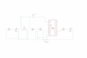
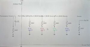
Assignment 9: Rate Your Mood

Concept & Inspiration:

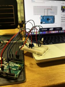
For this week’s project, we had to find a way to use both an analog and digital method to turn on a led light. I decided to use a button for my digital sensor, and a potentiometer for my analog sensor. My original idea was to use the button to change the colors of the two RBG led lights to represent different emotions and the potentiometer to change how dim or bright that emotion is for the day. For example, yellow being happiness, red being anger, blue being gloomy, purple as spirituality, etc. I tried to follow some tutorials, but it ended up being a bit too complicated, so I stuck to what we knew.

To rate your mood, users can twist the potentiometer to match how good they’re feeling, with the maximum blinking light representing them having a fantastic day. The button is a “feel good button,” meant to help users reduce their stress by fidgeting with a button that turns on with each click. The satisfying sounds may be soothing to some.

Demo Video:

Rate Your Mood

Github Link:

Rate Your Mood .ino File

Highlight Code:

if(buttonState == HIGH){
  digitalWrite(13,HIGH);
} else {
  digitalWrite(13,LOW);
}

The code I used is basically the exact same as the one we worked on in class while learning about digital input/output, except I made it so that the light was originally off and would turn on if the circuit is complete. Meanwhile in class, it was originally on and would turn off if the circuit was complete. This is highlighted because the feel good button is more satisfying when each click turns on the light, rather than turns off the light

Reflection + Future Improvements:

Overall, I’m still satisfied with how this project turned out. I got to use a new item (the RBG led light) and even though I didn’t get to use it the way I wished and planned for, I still got to use it for its automatic blinking that starts when the potentiometer is maximized. I didn’t do any of that with code, which was really cool. In the future, I would really like to expand on and execute the initial idea I had, to make the colors change with the button. In that case, I would also like to find a different way to create a “feel good button” or some other kind of satisfying fidget since the button would have a different purpose

Assignment 6: Overspending Warning

Concept:

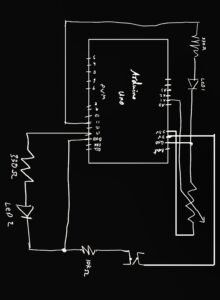
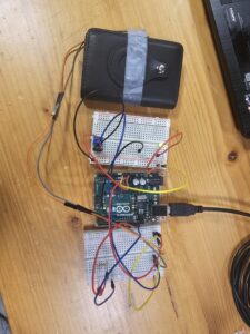
For this assignment, we were asked to control one LED in an analog manner and another in a digital manner. I chose to use a button switch to control one LED and a potentiometer for the other. For the digital component, I attached a button switch to my wallet’s card-ejection button so that whenever I try to access my credit card, a red LED lights up as a gentle warning to consider my spending. For the analog component, I connected a potentiometer to a blinking LED, allowing the speed of the LED’s blinking to be adjusted by turning the potentiometer. This setup demonstrates both analog and digital LED control in a creative, practical application.

Highlight:

A key highlight of this project is my approach to keeping the analog and digital circuits distinct from each other. By treating them as separate circuits, I chose to use the Arduino’s 5V and 3.3V power outputs individually powering the digital circuit with 5V and the analog circuit with 3.3V. Additionally, I set up each circuit on separate breadboards, which makes it easy to distinguish between the two and ensures a clear, organized layout. This setup not only reinforces the conceptual differences between analog and digital control but also simplifies troubleshooting and testing.

Hand-Drawn Schematic

For the coding aspect of this project, I organized the code by designating separate blocks for the analog and digital controls, clearly separated by comments. This structure makes the code easier to navigate and understand, as each section is dedicated to controlling one LED independently.

In the blinking LED project, I utilized the map function, as we covered in class, to control the blinking speed with the potentiometer. By mapping the potentiometer’s analog input range (0–1023) to a delay range (e.g., 50–1000 milliseconds), I was able to adjust the blink rate based on the potentiometer’s position.

int led = 11;

void setup() {
 Serial.begin(9600);

 pinMode(led, OUTPUT);
 pinMode(13, OUTPUT);
 pinMode(A2, INPUT);

}

void loop() {
//controlling led with a potentiometer
    int sensorValue = analogRead(A1);
    Serial.println(sensorValue);

    // Map the potentiometer value (0–1023) to a delay time (e.g., 50–1000 ms)
    int blinkDelay = map(sensorValue, 0, 1023, 50, 1000);

    // Blink the LED at a speed controlled by the potentiometer
    digitalWrite(led, HIGH); 
    delay(blinkDelay);        
    digitalWrite(led, LOW);    
    delay(blinkDelay);         

//Controlling Led with a Button
int buttonState = digitalRead(A2);
if (buttonState == LOW) {
digitalWrite(13, LOW);
} else {
digitalWrite(13, HIGH);
}

}

Demonstration:

Digital Circuit

Analog Circuit

Complete Setup

Reading Response 6

Physical Computing’s Greatest hits and misses

“Physical Computing’s Greatest Hits and Misses” dives into the ups and downs of integrating digital technology into physical spaces, and I found myself agreeing with the need to balance innovation with usability. One example that came to mind as a “hit” is the interactive installations in museums, like touch-sensitive displays or motion sensors that respond to visitors. These installations really enhance the experience, letting people interact with exhibits in ways that feel natural and fun. They show how physical computing can deepen engagement and create memorable experiences.

On the other hand, a “miss” for me is voice-activated assistants in public spaces, like Alexa in hotel rooms. While it’s a cool idea, it doesn’t always feel necessary, and privacy concerns can make people uncomfortable. Sometimes, it feels like technology is added just for the sake of being trendy, without actually improving the experience for the user.

Overall, I appreciated how the article doesn’t just celebrate successes but also reflects on what didn’t work, and why. It’s a good reminder for anyone working in this space (including me!) to think carefully about the purpose and impact of our designs. It’s not just about “what’s possible” but about making something genuinely useful or meaningful.

Making Interactive Art: Set the Stage, Then Shut Up and Listen

In Making Interactive Art: Set the Stage, Then Shut Up and Listen, the author emphasizes the importance of giving users freedom to explore interactive art without over-directing them. Instead of telling people exactly what to do, artists are encouraged to “set the stage” and then let go, allowing the audience to interpret and respond to the work in their own way. I found this approach both challenging and refreshing. The idea of “listening” to users without controlling the experience forces artists to think deeply about how a piece can evoke curiosity and provide a space for discovery.

One part that resonated with me was the focus on creating an environment where users feel empowered to participate. For instance, I’ve noticed that some of the most compelling interactive pieces in galleries are ones that give minimal instructions. People get to be more creative, exploring the piece however they like. These open-ended approaches make each interaction feel personal and unique.

Overall, this article challenges traditional thinking in art and interactivity, making a strong case for why artists should relinquish control and let audiences truly experience the work. As someone working in interactive media, it’s a powerful reminder that art is often most impactful when it becomes a two-way conversation rather than a one-sided display.

Reading Reflection – Week 9

Physical Computing’s Greatest Hits (and misses):

Copying and originality are quite controversial topics when it comes to art, especially AI art. We tend to try to come up with fully new concepts, as some of our ideas might sound a bit too similar to preexisting concepts. This article talks about how it’s okay if your idea isn’t original, because there’s opportunities for you to make it so. The repetitiveness of certain project themes in physical computing can help users, especially those new to physical computing, learn to create variations of works that inspire them. It is a great means to study and learn concepts that are foreign to you, as you can recreate the work and later build onto it and make it more your own.

I like how the author encourages people to keep going through with an idea even though they think it’s not original. As someone who is still a beginner at physical computing, recreating unoriginal work is a great way to gain experience at the methods, while not needing the brain power to come up with something new when I don’t even understand the basics. The list will come in handy to me as gloves, video mirrors, and things you yell at are in my interest. I like how he also mentions the potential drawbacks of a few of the themes, and explains a situations where that could occur.

Making Interactive Art: Set the Stage, Then Shut Up and Listen:

I liked how almost brutal and straight to the point the author is about the concept of only being able to guide the audience through your interactive work and then shutting up and letting them work their way around your piece on their own. He makes a lot of good points about having to let the audience/users think for themselves when it comes to interpreting interactive art, and the acting example was a wonderful way of putting that necessary autonomy into perspective.

“You can suggest intentions, but you can’t give him interpretations. You can give him props to work with, or place them in the way so he’ll discover them. You can suggest actions, but you can’t tell him how to feel about those actions; he will have to find it for himself.”

It actually reminded me of a recent interaction I had with a friend who needed feedback on his Sound Project. It’s a project solely focusing on audio, with no visuals, and I got a bit lost by the middle and he had to explain what was happening for me to get it. Reading this piece reminded me of that because my interpretation of it wasn’t exactly how he wanted it to be, but he couldn’t just force those ideas into my head. Even after his explanation, I still couldn’t hear what he was pointing out, so my interpretation of his project would’ve been great feedback for him, since it would allow him to see from a perspective where he isn’t interpreting his own work. He can work on “setting the stage more” now that he has “shut up and listened.”

Assignment 7 – Sensor and Push Button

Concept

For this assignment I used two different LED lights one is switched on my a push button, and the other changes it’s brightness based on the lighting detected by the light sensor.

Code

int led = 11;

void setup(){
  Serial.begin(9600);
  pinMode(led,OUTPUT);
}

void loop(){
  int sensorValue = analogRead(A2);
  Serial.println(sensorValue);
  analogWrite(led,sensorValue/4);
  delay(50);
}

Github

Setup

The setup was drawn using Tinkercad

Schematic

The schematic was drawn using Tinkercad

Demonstration

Video


Week 8: Unusual Switch: The Gravity Switch

Concept

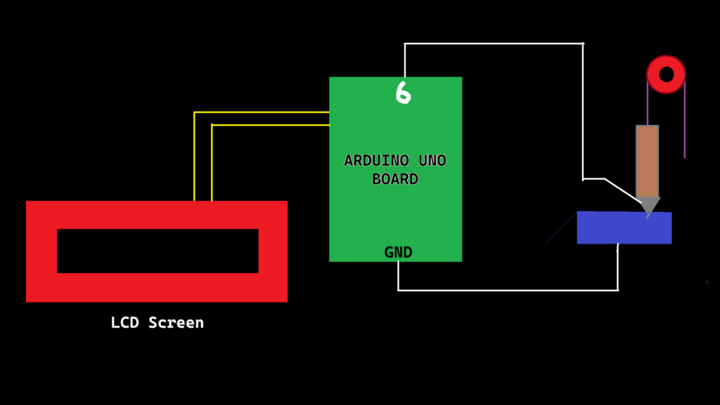
This assignment is the most unique one as at the most basic level, we had to utilize the physical systems around us to make or break a circuit. That’s why I decided to use an everyday tool- the pulley to control the flow of electricity. Rather than pressing a button or flipping a switch, the user plays a more active role in balancing forces. The switch itself is a rotating beam with a conducting end, which is lifted or dropped through a pulley mechanism onto a conductive plate. By carefully adding or removing weights, the user must balance or offset gravity to either make or break the connection. A simple two dimensional diagram of the same looks like this:
 

And the circuit schematic is:
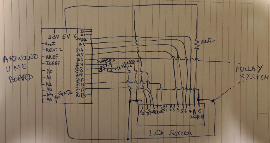
Circuit Schematic

The Physics behind it

When the weight of the external weights added create enough torque to lift the heavy end of the beam, the lighter end of the beam (the one having the conducting pin), moves down to touch the conducting plate, completing the circuit and prompting the “LOW” state (because of the Pullup Input).

This state is pivotal, as it is needed to switch which LED lights up in the Arduino. Simply put, we use the red LED for stopping the user to add weight in the pan (which is associated to the “HIGH” state of the switch) and green LED to continue adding the weights (which is associated to the “LOW” state of the switch).

Thus, the Gravity Switch, which uses a Simple Pulley mechanism, Physics and Arduino actualy behaves as a “Toggle Switch,” but we don’t user our hands in a direct way. We simply rely on Gravity to do the connecting part for us.

Code Implementation

The only library imported was the LCD Library “Liquid Crystal.h”.

Now, according to the code:

// Including the required libraries
# include <LiquidCrystal.h>

// Initialize the library with the numbers of the interface pins
LiquidCrystal lcd(12, 11, 5, 4, 3, 2);
const int contrast = 90;
const int contrastPin = 9;

// Defining the Global Variables
// Defining the LED pins
const int redLEDPin = 8;     // Pin used for reading the state of the switch of Red LED
const int greenLEDPin = 7;   // Pin used for reading the state of the switch of Green LED

// Defining the switch pin 
const int switchPin = 6;     // Pin used for reading the switch state to decide which LED lights up
int switchState;
int previousSwitchState = -1;

// Setup Function
void setup() {
  // Setting the Pin to Input to read its state
  pinMode(redLEDPin, OUTPUT);
  pinMode(greenLEDPin, OUTPUT);
  pinMode(switchPin, INPUT_PULLUP);

  // Initialize the LCD and set up the columns and rows
  lcd.begin(16, 2);
  delay(500);

  // Setting up the contrast for LCD Display as not using Potentiommeter
  analogWrite(contrastPin, contrast);
  Serial.begin(9600);
}

// Loop Function
void loop() {
  switchState = digitalRead(switchPin);

  // Only clear and update the LCD when the switch state changes
  if (switchState != previousSwitchState) {
    lcd.clear();  // Clear the screen only when the state changes

    if (switchState == LOW) {
      lcd.setCursor(0, 0);
      lcd.print("Switch is ON.");
      lcd.setCursor(0, 1);
      lcd.print("Add more weight!");

      Serial.println("SWITCH STATE IS HIGH ");
      digitalWrite(greenLEDPin, HIGH);
      digitalWrite(redLEDPin, LOW);
    }
    
    else {
      lcd.setCursor(0, 0);
      lcd.print("Switch is OFF.");
      lcd.setCursor(0, 1);
      lcd.print("HALT THE WEIGHTS");

      Serial.println("SWITCH STATE IS LOW");
      digitalWrite(redLEDPin, HIGH);
      digitalWrite(greenLEDPin, LOW);
    }

    previousSwitchState = switchState;  // Update the previous state
  }

  delay(100);
}

In the code, I have used the pins 2, 3, 4, 5, 11 and 12 for the D4, D5, D6, D7, Enable, and RS pin on the LCD Display. I have used a fixed 10k Ohm resistor instead of the potentiometer for the contrast level (As we don’t want to use our hands directly in any part of the project).

Also, Pin 6 is the main switch pin which is responsible for reading the state, and the entire circuit (+ LCD) behaves according to the state.

Head Scracthing Software Problems faced

In communicating with the LCD Screen, some problems were faced, notably the random toggling of the switch input when it was not connected. This was caused by a floating input pin – a common issue in digital electronics. A floating pin picks up electrical noise, resulting in irregular behavior. The solution involved enabling the internal pull-up resistor using “INPUT_PULLUP” on the switch pin. This ensures that the switch pin has a default state of HIGH when not pressed, making the input stable and reliable. (I got to know about this from the Arduino Forum: https://forum.arduino.cc/t/arduino-input-seems-to-be-randomly-toggling/448151)

Another issue was the LCD displaying random characters in a flow instead of the expected text. This issue had multiple causes: frequent clearing of the display, incorrect contrast settings, and potential timing issues during initialization. The frequent use of lcd.clear() in every loop iteration was causing the screen to flicker and show inconsistent outputs. By refactoring the code to only clear the LCD when the switch state changed, the display became stable and only updated when necessary, improving both performance and readability.

Demonstration Video

Problems associated

  • If the user puts too weight, the beam or the conducting pin can bend or break, which will make the circuit useless.
  • One can also lift the beam by themselves to make the pin touch the conducting plate, but that defeats the purpose of the assignment.
  • I also wanted a smaller more heavier block which has the Pin 6 installed as the main weight, but the closest I could get was that block in the demonstration video.
  • I wanted to use the Slot weights like these:

which are typically used in Physics experiments (but I could not find them anywhere *sad noises*)

Week 9

Project: Dual-Control LED System with LDR Night Light and Button-Controlled LED

 Concept

This project explores the integration of analog and digital controls using an LDR (Light Dependent Resistor) and a button to control two LEDs. The first LED functions as an automatic night light, turning on in low-light conditions as detected by the LDR. The second LED is controlled by a button, which allows the user to toggle it on and off. This setup demonstrates the use of both analog and digital inputs to create interactive light control.

Design and Execution

Components
– LDR: Senses ambient light and provides analog input for the night light.
– Button: Serves as a digital switch for the second LED.
– LED 1: Acts as a night light that responds to light levels.
– LED 2: Controlled by the button for manual on/off functionality.
– 220Ω Resistors: Limit current to protect the LEDs.

Schematic Diagram

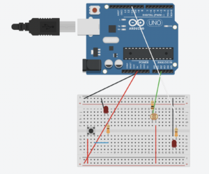
The circuit is designed on a breadboard, with the LDR setup on one side and the button on the other. Power and ground rails connect both sides to the Arduino.

1. LDR Circuit: Creates a voltage divider with a 10kΩ resistor connected to analog pin A0.
2. Button Circuit: Connected to digital pin 7 with an internal pull-up resistor enabled in the code.
3. LEDs: LED 1 is controlled by the LDR (analog), and LED 2 by the button (digital).

Code

// Dual-Control LED System: LDR and Button

// Pin definitions
const int led1 = 8;            // LED for night light (LDR-based)
const int sensorPin = A0;      // LDR sensor pin
const int buttonPin = 7;       // Button pin for second LED control
const int led2 = 9;            // Second LED pin (button-controlled)

// Threshold for LDR to turn on the night light
const int threshold = 500;     // Adjust based on ambient light

// Variables
int sensorValue;               // LDR sensor reading
int buttonState;               // Button state

void setup() {
  pinMode(led1, OUTPUT);             // Set LED1 as output
  pinMode(buttonPin, INPUT_PULLUP);  // Set button as input with pull-up
  pinMode(led2, OUTPUT);             // Set LED2 as output
  Serial.begin(9600);                // Initialize serial communication
}

void loop() {
  // LDR-controlled LED (Night Light)
  sensorValue = analogRead(sensorPin);  // Read LDR value
  Serial.println(sensorValue);          // Print for debugging
  
  if(sensorValue < threshold) {         // If below threshold, turn on LED1
    digitalWrite(led1, HIGH);
  } else {                              // Otherwise, turn off LED1
    digitalWrite(led1, LOW);
  }

  // Button-controlled LED
  buttonState = digitalRead(buttonPin); // Read button state
  if (buttonState == LOW) {             // If button is pressed
    digitalWrite(led2, HIGH);           // Turn on LED2
  } else {
    digitalWrite(led2, LOW);            // Turn off LED2
  }
  delay(100); // Small delay for stability
}


Observations

– Night Light Sensitivity: The LDR-based LED responds to ambient light, offering a basic “automatic night light” functionality. The threshold value can be adjusted to suit different lighting conditions.
– Button Responsiveness: The button controls the second LED reliably, allowing manual toggling.

Video Demonstration

https://drive.google.com/file/d/1wugSSY6orAYq02qOQg9335lDeIQAwCms/view?usp=drive_link

Reflection and Future Improvements

This project demonstrates the integration of analog and digital inputs for LED control, offering insights into how sensors can drive interactive behavior. Future improvements could include adding adjustable sensitivity for the night light or introducing more complex patterns for the button-controlled LED.

This project enhanced my understanding of basic sensor interactions, providing a foundation for more advanced input/output controls in Arduino projects.

Week 9 Reading Response

Reading about classic physical computing projects, I was struck by how these interactive experiences allowed creative personalization. I was greatly inspired by how simply notions of time space and senses could be creatively challenged and it is a task that I intend to do in my phyiscal computing projects going forward.

The theremin-like instruments idea resonated greatly with me. I’d love to explore creating music through hand gestures, adding subtle layers that shift tone and pitch, channeling emotions through motion. Similarly, the glove-based instruments brought to mind using gloves to play sounds with a touch or pinch, bridging the digital and physical in a poetic way. Hands are the way we interact most closely with the world, and having them be the bridge that transcends the physical and virtual is inherently poetic.

The video mirror section made me think about my interest in using computer vision thoughtfully in art. I’d love to create a mirror that captures shadows or movements subtly, making it feel like a shared, non-intrusive moment.

The yell-activated projects felt liberating, inspiring thoughts on using sound to create splashes of color, encouraging expressive, even chaotic, engagement with tech. The passion involved in a scream or a loud sound, uncaring for your environment and showing vulnerability, are all themes that I wish to explore further.

Reading about these timeless projects has me excited to experiment with ways to make them my own. Physical computing offers an amazing canvas, and I would love to take a deeper dive into these topics so that I can hopefully inspire someone too like I was inspired reading about these projects.

Tom Igoe’s article, “Making Interactive Art: Set the Stage, Then Shut Up and Listen,” emphasized that artists should let their interactive artwork speak for itself, rather than over-explaining it. According to Igoe, artists often script or interpret every part of their work, potentially limiting participants’ personal engagement. Instead, Igoe argues that interactive art should initiate a dialogue, allowing the audience to explore, interpret, and react in their own way. He compares this to a director’s approach with actors, guiding without dictating emotions, letting authentic responses emerge. For interactive art, setting up the experience thoughtfully, then stepping back, creates a collaborative process where the audience completes the piece through interaction. I realised that often in my own work, I do not allow the space for that creativity which hinders how interactive they can be. If the observer is first faced with my viewpoint and then the art itself, they will only be able to see it from my eye. This reading gives me motivation to learn to separate the art from the artist in my own and other’s art and let my work flourish and have a voice of its own.

READING #WEEK 9

“Making Interactive Art: Set the Stage, Then Shut Up and Listen” by Tom Igoe was an interesting look at interactive art. It seemed like Igoe’s advice to not over-explain our work and let viewers make up their own minds about it was trying to say that art can be more than just a one-way statement. For instance, by letting people interact without being told what to do, we’re having them finish the piece through their own experiences.

This made me think of Yayoi Kusama’s “The Obliteration Room.” Igoe said that art is like directing players; the artist sets the scene but doesn’t control every action. Kusama makes a room that is all white and tells people to cover it with colorful dot stickers in any way they want. She doesn’t tell them where or how to put the dots; the audience is the only one who can change the room. It turns into a lively group work over time, with each person’s choices shaping it. I felt that this example was like Igoe’s concept of stepping back and letting go, allowing people to experience art in their own way.

This concept of letting go and allowing for freedom in interpretation also ties into Igoe’s approach in “Physical Computing’s Greatest Hits (and Misses)”. Here, he similarly emphasizes the value of exploring foundational themes and encourages creativity without fear of being unoriginal. Rather than chasing entirely new ideas, he urges creators to build upon recurring themes in physical computing, adding their own twist.

What I liked about this example was the “theremin like instruments.” It says that even though making a simple theremin is fun, it doesn’t always allow for useful interaction. This example showed me that even though the projects are easy, they can still push the people who make them to think beyond the basics and look for ways to give the interaction more meaning. Whether in art or software, I think both readings support the idea that effective interactive work emerges when the author takes a backseat, encourages individual interaction, and has faith in the audience to realize their interpretations.

Week 9 Sunrise Project

Concept:

The idea for this project came from something I’ve always found fascinating: the transition from night to day, especially the way streetlights turn off as the new day begins and the sun begins to rise.
I’ve always been captivated by the natural beauty of a sunrise, how the sky gradually shifts colors as the day begins.  The goal was to create something interactive where turning off a “streetlight” (represented by a blue LED) would trigger a sunrise sequence using an RGB LED. I used a photoresistor that detects the change in light when the streetlight is turned off, this then turns on the RGB light sequence.

Demonstration:

Code:

const int blue_led_pin = 9;         // Blue light (streetlight)
const int switch_pin = 2;           // Switch pin
const int photo_resistor_pin = A0;  // Photoresistor pin
const int red_pin = 3;              // Red pin of RGB 
const int green_pin = 5;            // Green pin of RGB 
const int blue_pin = 6;             // Blue pin of RGB

// Variables
bool streetlight_on = true;         // bool to track if the stretlight is on
bool sunrise_started = false;       // bool to track is the sunrise sequence has started

void setup() {
  // Initialize pins
  pinMode(blue_led_pin, OUTPUT);
  pinMode(switch_pin, INPUT);

  pinMode(red_pin, OUTPUT);
  pinMode(green_pin, OUTPUT);
  pinMode(blue_pin, OUTPUT);

  // streetlight starts off as on
  digitalWrite(blue_led_pin, HIGH);
}

void loop() {
  // Check if the switch is pressed
  if (digitalRead(switch_pin) == HIGH && streetlight_on) {
    digitalWrite(blue_led_pin, LOW);   // Turn off streetlight
    streetlight_on = false;            // change the bool to reflect the streetlight being off
  }

  // Read light level from photoresistor
  int light_level = analogRead(photo_resistor_pin);

  // If light level drops below threshold, start sunrise sequence, can be if the blue light turns off or if the light is manually blocked
  if ( !sunrise_started && light_level < 500) { 
    sunrise_effect();
    sunrise_started = true;            // bool confirms that sunrise has started
  }
}

void sunrise_effect() {
  // Gradually change colors like a sunrise
  for (int i = 0; i <= 255; i++) {
    analogWrite(red_pin, i);           // Increase red brightness first
    delay(30);                         // Adjust delay for smooth transition

    if (i > 100) {
      analogWrite(green_pin, i - 100); // Add green for yellow/orange colors
    }

    if (i > 200) {
      analogWrite(blue_pin, i - 200);   // Add blue for full white at to show noon
    }

    delay(30);
  }
}

Schematics:

Workings:

The blue led is shone directly into a photoresistor. When the switch is used to turn it off, the photoresistor reading goes down which triggers the sunrise sequence on the rgb led. It is demonstrated that the photoresistor triggers the sequence and not the button press as even when the photoresistor is covered with a finger with the blue led on, the reading goes down and the sunrise sequence is initiated.

Future Considerations:

I had tremendous fun working on this project especially learning how the rgb led works. In the future I’d like to add more leds which trigger different sequences in the rgb led or perhaps a sound aspect to it as well where a loud sound triggers the sequence.