Reading Reflection – Week 12

Personally, I liked this reading. The article Design meets Disability, mentions points which I hadn’t previously considered but are intuitive. While the author gave multiple examples of designs that were made to be more accessible while not highlighting one’s disability there were a few that stood out to me.

The most obvious product which is meant to help people with a disability are glasses. Like the article mentioned people don’t view glasses the same way as a wheelchair or a crutch or an arm sling. People see glasses as aesthetically appealing and as someone that wears glasses I haven’t seen as it as a disability either. I believe that the reason for this is mostly that glasses are very commonplace but that also they can be both aesthetically appealing and discrete.

The theme of aesthetically appealing and discrete is consistent for designs that are meant to also help those with a disability. The author mentioned the iPod but really it made me consider a previous reading we had. The previous reading discussed how something that is aesthetically appealing can be helpful for creativity and that people are willing to overlook small details. I wondered if a product that may not be as technically advanced as another can still sell more if the user-experience is far greater. I think this has already been shown to be the case with the Macintosh, and Macs in general, but also the iPhone which has a cult-following (including myself). While some people stick to the iPhone because of the apple ecosystem being very convenient I think a lot of people (and I am speaking from anecdotal experiences) like the user-interface both because it is intuitive and aesthetically appealing whilst being discrete, and because they have been using it for such a long time that it’s inconvenient to change. Many android phones have better features and some are cheaper and yet people, like myself, still choose to buy an iPhone.

Going into the final project now I want to try to make the design aesthetically appealing and keep certain parts discrete depending on the function. For example any buttons or switches that should be used by the players will be easy to see and everything else will hopefully add to the aesthetic whilst not being distracting. Hopefully I can have this done before user-testing so that I can change it before the final deadline if needed.

Week 12 : Production (Pi, Darko)

These are IM Week 12 Assignments by Pi and Darko

Production 1

Make something that uses only one sensor  on Arduino and makes the ellipse in p5 move on the horizontal axis, in the middle of the screen, and nothing on arduino is controlled by p5

let rVal = 0;
let alpha = 255;
let left = 0; // True (1) if mouse is being clicked on left side of screen
let right = 0; // True (1) if mouse is being clicked on right side of screen
let xPos = 0; // Position of the ellipse

function setup() {
  createCanvas(640, 480);
  textSize(18);
  noStroke();
}

function draw() {
  // one value from Arduino controls the background's red color
  background(255, 255, 255);

  // Update the position of the ellipse based on the alpha value
  // Mapping alpha to the width of the canvas
  xPos = map(alpha, 0, 1023, 0, width);

  // Draw an ellipse that moves horizontally across the canvas
  fill(255, 0, 255, 255); // Same mapping as the text transparency
  ellipse(xPos, height / 2, 50, 50); // Position ellipse at center height with a diameter of 50

  if (!serialActive) {
    text("Press Space Bar to select Serial Port", 20, 30);
  } else {
    text("Connected", 20, 30);

    // Print the current values
    text('rVal = ' + str(rVal), 20, 50);
    text('alpha = ' + str(alpha), 20, 70);
  }

}

function keyPressed() {
  if (key == " ") {
    // important to have in order to start the serial connection!!
    setUpSerial();
  }
}

function readSerial(data) {
  if (data != null) {
    let fromArduino = split(trim(data), ",");
    if (fromArduino.length == 2) {
      rVal = int(fromArduino[0]);
      alpha = int(fromArduino[1]);
    }
   
    let sendToArduino = left + "," + right + "\n";
    writeSerial(sendToArduino);
  }
}


Production 2

Make something that controls the LED brightness from p5

let rVal = 0;
let alpha = 255;
let left = 0; // True (1) if mouse is being clicked on left side of screen
let right = 0; // True (1) if mouse is being clicked on right side of screen
let xPos = 0; // Position of the ellipse
let ledState = false; // To toggle LEDs


function setup() {
  createCanvas(640, 480);
  textSize(18);
  noStroke();
}

function draw() {
  // one value from Arduino controls the background's red color
  background(255, 255, 255);

  // Update the position of the ellipse based on the alpha value
  // Mapping alpha to the width of the canvas
  xPos = map(alpha, 0, 1023, 0, width);


  if (!serialActive) {
    text("Press Space Bar to select Serial Port", 20, 30);
  } else {
    text("Connected", 20, 30);

    // Print the current values
    text('rVal = ' + str(rVal), 20, 50);
    text('alpha = ' + str(alpha), 20, 70);
  }
 
 
  text("Then, press A to flash the police lights.",20, 100)
  //Edit the code below
  // Toggle LED state every frame if space is held down
  if (keyIsDown(65)) { // 32 is the ASCII code for space
    ledState = !ledState;
    if (ledState) {
      left = 1;
      right = 0;
    } else {
      left = 0;
      right = 1;
    }
  }
  // Edit the code above

}

function keyPressed() {
  if (key == " ") {
    // important to have in order to start the serial connection!!
    setUpSerial();
  }
}

function keyReleased(){
  if (key == "a") {
   left = 0;
      right = 0;


  }
}

function readSerial(data) {
  if (data != null) {
    let fromArduino = split(trim(data), ",");
    if (fromArduino.length == 2) {
      rVal = int(fromArduino[0]);
      alpha = int(fromArduino[1]);
    }
   
    let sendToArduino = left + "," + right + "\n";
    writeSerial(sendToArduino);
  }
}


Gravity Wind

Take the gravity wind example (https://editor.p5js.org/aaronsherwood/sketches/I7iQrNCul) and make it so every time the ball bounces one led lights up and then turns off, and you can control the wind from one analog sensor

let velocity;
let gravity;
let position;
let acceleration;
let wind;
let drag = 0.99;
let mass = 50;
let rVal = 0;
let alpha = 255;
let left = 0; // True (1) if mouse is being clicked on left side of screen
let right = 0; // True (1) if mouse is being clicked on right side of screen
let serialSetup = false;
// Declare a variable to store the time at which to trigger the action
let triggerTime = 0;

function setup() {
  createCanvas(640, 360);
  noFill();
  position = createVector(width / 2, 0);
  velocity = createVector(0, 0);
  acceleration = createVector(0, 0);
  gravity = createVector(0, 0.5 * mass);
  wind = createVector(0, 0);
  // Set the trigger time to be 5 seconds after setup runs
  triggerTime = millis() + 5000;
  textSize(20);
}

function draw() {
  // Check if the current time has passed the trigger time
  if (millis() >= triggerTime && !serialSetup) {
    serialSetup = true;
  }
  push();
  fill(0);
  if (!serialSetup) {
    text("Simulation starts in 5 seconds. Press a to set up serial.", 20, 50);
  }
  pop();

  if (serialSetup) {
    background(255);
    let windtext = "";
    if (alpha < 300) {
      wind.x = -1;
      windtext = "Wind : Right";
    } else if (alpha > 800) {
      wind.x = 1;
      windtext = "Wind : Left";
    } else {
      wind.x = 0;
      windtext = "No wind.";
    }

    push();
    fill(0);

    text(windtext, 20, 50);
    pop();

    applyForce(wind);
    applyForce(gravity);
    velocity.add(acceleration);
    velocity.mult(drag);
    position.add(velocity);
    acceleration.mult(0);
    ellipse(position.x, position.y, mass, mass);
    if (position.y > height - mass / 2) {
      velocity.y *= -0.9; // A little dampening when hitting the bottom
      position.y = height - mass / 2;
      console.log(
        "Bounce! Position Y: " + position.y + ", Velocity Y: " + velocity.y
      );
      left = 1;
    } else {
      left = 0;
    }
  }
}

function applyForce(force) {
  // Newton's 2nd law: F = M * A
  // or A = F / M
  let f = p5.Vector.div(force, mass);
  acceleration.add(f);
}

function keyPressed() {
  if (keyCode == LEFT_ARROW) {
    wind.x = -1;
  }
  if (keyCode == RIGHT_ARROW) {
    wind.x = 1;
  }
  if (key == " ") {
    mass = random(15, 80);
    position.y = -mass;
    velocity.mult(0);
  }
  if (key == "a") {
    // important to have in order to start the serial connection!!
    setUpSerial();
  }
}

// This function will be called by the web-serial library
// with each new *line* of data. The serial library reads
// the data until the newline and then gives it to us through
// this callback function
function readSerial(data) {
  ////////////////////////////////////
  //READ FROM ARDUINO HERE
  ////////////////////////////////////

  if (data != null) {
    // make sure there is actually a message
    // split the message
    let fromArduino = split(trim(data), ",");
    // if the right length, then proceed
    if (fromArduino.length == 2) {
      // only store values here
      // do everything with those values in the main draw loop

      // We take the string we get from Arduino and explicitly
      // convert it to a number by using int()
      // e.g. "103" becomes 103
      rVal = int(fromArduino[0]);
      alpha = int(fromArduino[1]);
    }

    //////////////////////////////////
    //SEND TO ARDUINO HERE (handshake)
    //////////////////////////////////
    let sendToArduino = left + "," + right + "\n";
    writeSerial(sendToArduino);
  }
}


Final Project Progress | GyroMaze

For my final project, I have locked in on the idea of using a gyroscope device to control a ball inside a maze. Since then, I’ve successfully booked the equipment I need from Arts Booking and made considerable progress for my project.

~~The Maze~~

I utilized the p5 play library to help me build the game managers. I loaded two sprites: a cube and a black tile. The cube acts as the player, whereas the tile serves as the wall for the maze. These can be changed at any time.

let map = 
    [
    "@@@@@@@@@",
    "@   @   @",
    "@@@ @ @ @",
    "@@@   @ @",
    "@@@@@   @",
    "@@@@@@@@@",
    ];

new Tiles(map, 0.5, 0.5, 1, 1); //Those are the coordinates so that they start a bit right and not super too the edge of the windowWidth & windowHeight


Within the short period between the previous class, I was able to fully build the maze system complete with a character controller. The Tiles() function can read any list consisting of strings. Those strings are made out of @ and ‘SPACES’ to mark walls and empty space. Next, I made a separate list called map that has the layout of the whole maze. Hence, with this system, I can create as many mazes as I need to and easily implement a map randomizer for the final product.

if (kb.pressed('up') && isOpen(avatar.x, avatar.y-1)) {
    //SMOOTH MOVEMENT USING VECTOR
    avatar.moveTo(createVector(avatar.x, avatar.y-1), .1)
    
    //avatar.y--;

The character moves by a simple UP, DOWN, LEFT, RIGHT checking alongside isOpen() function. The function checks whether there is a ‘SPACE’ within the map. If there is, it returns true, which means the player can walk through it. If not, then there is a wall and the player cannot move through it.

~~The Physical Controller~~

The module that I booked from Equipments Center is a generic GY-85 sensor that comes with three features: an accelerometer, gyroscope, and magnetometer.

Help, it’s broken! (nope) Continue reading “Final Project Progress | GyroMaze”

Week 12 – Serial Communication (Group Assignment)

Team Members: Muhammed Hazza, Yaakulya Sabbani

Exercise 1: ARDUINO TO P5 COMMUNICATION

Something that uses only one sensor on arduino and makes the ellipse in p5 move on the horizontal axis, in the middle of the screen, and nothing on arduino is controlled by p5.

Arduino Code

void setup() {
  Serial.begin(9600);
  //pinMode(LED_BUILTIN, OUTPUT);

//start the handshake
  while (Serial.available() <= 0) {
    //digitalWrite(LED_BUILTIN, HIGH);
    Serial.println("0,0"); // send a starting message
    delay(300);
    //digitalWrite(LED_BUILTIN, LOW);
    delay(50);

  }
}

void loop() {
  // wait for data from p5 before doing something
  while (Serial.available()) {
     //digitalWrite(LED_BUILTIN, HIGH);
    int isMoving = Serial.parseInt();
    if (Serial.read() == '\n') {
      int photoVal = analogRead(A0); 
      delay(5);
      Serial.println(photoVal);
   }
  }
  //digitalWrite(LED_BUILTIN, LOW);
}

P5 code

// Initialize variables to store values from Arduino
let rVal = 0; // Stores the received value from Arduino
let xPos = 0; // Stores the mapped x-position value
let rad = 50; // Radius of the ellipse to be drawn

// Setup function - runs once at the beginning
function setup() {
  // Create a canvas with dimensions 400x400
  createCanvas(400, 400);
  // Set text size to 18 pixels
  textSize(18);
}  

// Draw function - runs continuously
function draw() {
  // Set background color to white
  background(255);

  // Check if serial communication is active
  if (!serialActive) {
    // Display message to prompt user to press Space Bar to select Serial Port
    text("Press Space Bar to select Serial Port", 20, 30);
  } else {
    // If serial communication is active, display "Connected" message
    text("Connected", 20, 30);
    
    // Map the received value (rVal) to the x-position within the canvas
    xPos = map(rVal, 0, 900, 0, 400);
    // Display the current received value (rVal)
    text('rVal = ' + str(rVal), 20, 50);
    // Draw an ellipse at the mapped x-position with fixed y-position (200) and radius (rad)
    ellipse(xPos, 200, rad, rad);
    // Display the mapped x-position (xPos)
    text('xPos = ' + str(xPos), 20, 70);
  }
}

// Function to handle key presses
function keyPressed() {
  // Check if Space Bar is pressed
  if (key == " ") {
    // Call setUpSerial() function to start serial connection
    setUpSerial();
  }
}

// Function to read data from Arduino
function readSerial(data) {
  // Check if data is not null
  if (data != null) {
    // Split the received data into an array using comma as delimiter
    let fromArduino = split(trim(data), ",");
    
    // Check if the array contains only one element
    if (fromArduino.length == 1) {
      // Update rVal with the received value from Arduino
      rVal = fromArduino[0];
    }
    
    // Send a handshake message to Arduino
    let sendToArduino = 1 + "\n";
    writeSerial(sendToArduino);
  }
}

Schematic

Video Demonstation

Exercise 2: P5 TO ARDUINO COMMUNICATION

Something that controls the LED brightness from p5.

Arduino Code

//Exercise 2 Arduino Code

const int ledPin =9;
int brightness = 0;
void setup() {
  Serial.begin(9600); // This will start serial communication at 9600 bps

  pinMode(LED_BUILTIN, OUTPUT);
  pinMode(ledPin, OUTPUT);
// start the handshake
  while (Serial.available() <= 0) {
    digitalWrite(LED_BUILTIN, HIGH); // on blink when waiting for serial data
    Serial.println("0,0"); // sending a starting message 
    delay(300);            // waiting for the delar
  }
}
void loop() 
{
  // wait for data from p5 before doing something
    while (Serial.available()) 
    {
    digitalWrite(LED_BUILTIN, HIGH); // led on while receiving data
    int brightness = Serial.parseInt(); //get slider value from p5
    Serial.println(brightness); //just to view the value
    
     if (Serial.read() == '\n') {
       analogWrite(ledPin, brightness); // will set brightness of LED
     
      }else
      {
        digitalWrite(LED_BUILTIN, HIGH);
      }
    }
}

P5 Code

//Exercise 2 - P5js Code
let slider;
function setup() {
   createCanvas(400, 400); // Creating canvas of 400x400 pixels
  slider = createSlider("0, 255, 0");
  slider.position(100, height/2); // Set the position of the slider
  slider.style('width', '80px'); // Set the width of the slider 
 
  
  noStroke(); // No stroke for the ellipse initially
}
function draw() {
  
  background(255); // Refresh background on each frame
  
  if (!serialActive) {
    text("Press Space Bar to select Serial Port", 20, 30);
  } else {
    text("Connected", 20, 30);}
}
function keyPressed() {
  if (key == " ") {
    // setting the serial connection!!
    setUpSerial();
  }   
}
// this callback function
function readSerial(data) {
    ////////////////////////////////////
    //READ FROM ARDUINO HERE
    ////////////////////////////////////
    //////////////////////////////////
    //SEND TO ARDUINO HERE (handshake)
    //////////////////////////////////
    console.log(slider.value());
    let sendToArduino = slider.value() + "\n";
    writeSerial(sendToArduino);
  
}

Video Demonstration


Schematic

Exercise 3: BI-DIRECTIONAL COMMUNICATION

Every time the ball bounces one led lights up and then turns off, potentiometer is used as the analog sensor to control the wind.

Arduino Code

//Exercise 3 Arduino Code

const int poten_pin = A0;
const int ledPin = 2;
void setup() {
 Serial.begin(9600); // Start serial communication at 9600 bps
 pinMode(LED_BUILTIN, OUTPUT);
 pinMode(ledPin, OUTPUT);
 pinMode(poten_pin, INPUT);
 // start the handshake
 while (Serial.available() <= 0) {
   digitalWrite(LED_BUILTIN, HIGH); // on/blink while waiting for serial data
   Serial.println("0,0"); // send a starting message
   delay(300);            // wait 1/3 second
   digitalWrite(LED_BUILTIN, LOW);
   delay(50);
 }
}
void loop()
{
 // wait for data from p5 before doing something
   while (Serial.available())
   {
     digitalWrite(LED_BUILTIN, HIGH);
     digitalWrite(ledPin, LOW);
//read the position of ball from p5
     int position = Serial.parseInt();
  
     if (Serial.read() == '\n') {
       // Read potentiometer value
     int sensorValue = analogRead(poten_pin);
     //send value to p5
     Serial.println(sensorValue);
     }
//if ball is touching the ground i.e. height is zero, turn LED on
     if (position == 0)
     {
       digitalWrite(ledPin, HIGH);
     }
     else{
       digitalWrite(ledPin, LOW);
     }
   }
     digitalWrite(LED_BUILTIN, LOW);
   }

p5 Code

//Exercise 3 - P5js Code

let velocity;
let gravity;
let position;
let acceleration;
let breeze;
let drag = 0.99;
let mass = 50;
let heightOfBall = 0;
function setup() {
  createCanvas(640, 360); // Create a canvas of 800x400 pixels
 
  noFill();
  position = createVector(width/2, 0);
  velocity = createVector(0,0);
  acceleration = createVector(0,0);
  gravity = createVector(0, 0.5*mass);
  breeze = createVector(0,0); 
}
function draw() {
  background(215);
  fill(0);
  
  if (!serialActive) {
    text("Press the space bar to select the serial Port", 20, 30);
  }
  else 
  {
    text("Arduino is connected! Press b to jump.", 20, 30);
  
  applyForce(breeze);
  applyForce(gravity);
  velocity.add(acceleration);
  velocity.mult(drag);
  position.add(velocity);
  acceleration.mult(0);
  ellipse(position.x,position.y,mass,mass);
    
  if (position.y > height-mass/2) {
      velocity.y *= -0.9;  // A little dampening when hitting the bottom
      position.y = height-mass/2;
    
    heightOfBall = 0;
    
    } 
    else {
      heightOfBall = 1;
    }
  }
}
function applyForce(force){
  // Newton's 2nd law: F = M * A
  // or A = F / M
  let f = p5.Vector.div(force, mass);
  acceleration.add(f);
}
function keyPressed() {
  if (key == " ") {
    // important to have in order to start the serial connection!!
    setUpSerial();
  }   
  else if (key=='b'){
    mass=random(15,80);
    position.y=-mass;
    velocity.mult(0);
  }
}
// this callback function
function readSerial(data) {
    ////////////////////////////////////
    //READ FROM ARDUINO HERE
    ////////////////////////////////////
  
     if (data != null) {
    // make sure there is actually a message
    
    let fromArduino = split(trim(data), ",");
    
       // if the right length, then proceed
    if (fromArduino.length == 1) {
//sensor value is the input from potentiometer
      let sensorVal = int(fromArduino[0]);
      
//potentiometer value ranges from 0 - 1023
//for values less than 400,wind blows to right
      if (sensorVal < 400){
        breeze.x=1
      }
//if value between 400 and 500, wind stops so ball stops
      else if(sensorVal >= 400 && sensorVal < 500){
        breeze.x = 0
      }
//if value greater than 500, wind blows to left
      else {
        breeze.x = -1
      }
          //////////////////////////////////
          //SEND TO ARDUINO HERE (handshake)
          //////////////////////////////////
    }
//height of ball sent to arduino to check if ball on floor or not
    let sendToArduino = heightOfBall  + "\n";
    writeSerial(sendToArduino);
  }
}

Schematic

Video Demonstration


Dachi Reading Response – Week 12

The author, Graham Pullin, makes an interesting case that the design of assistive technologies and products for people with disabilities has often been overly utilitarian and has neglected aesthetics, identity, and broader quality of life considerationsHe argues that assistive devices should be designed not just for narrow functionality but as fashionable, desirable consumer products that can enhance the user’s self-image and social interactions.

Pullin’s perspective aligns with the modern social model of disability, which holds that people are often more disabled by environmental and socio barriers rather than by their physical or mental impairments. Well-designed assistive products can help break down those barriers. And by making such products stylish and attractive to use, they may also help combat the stigma frequently associated with disability and assistive tech.

I agree with Pullin’s core ideas. Too often, assistive devices have looked medical, institutional, and perhaps alienating marking the user as different in a negative way. But that’s not always true. For example, Eyeglasses have evolved from purely functional visual aids to fashion accessories worn even by those who don’t medically require them. One could make an argument that other kinds of aids could potentially become part of someone’s fashion. 

The author argues for diversity and choices in design but this is not always desirableSometimes having too many choices just makes the user more confused as we discussed in earlier articles, and a more simplistic approach is the best. 

Redesigning already established tools won’t necessarily solve all the issues associated with the negative stigma surrounding disability. For example, you might improve wheelchair design, and make it more techy and futuristic, but again one will always see it as a wheelchair and I doubt it will become a fashion theme in the general public. Additionally, even if you improve wheelchair design, it’s all about the surrounding environment that makes it accessible, which should often be a key focus. With more complex design choices affordability becomes a problem. More elaborate choices in eyewear have made them pretty expensive where people chase brand values and collaborations rather than their actual utility. 

Despite, all these I firmly believe that creativity always emerges on top and people will find ways to make all “disability” associated designs more mainstream. Nevertheless, we should not forget that first of all, it’s about core utility and accessibility and less about mainstream fashion trends. If costs become marginal, then perhaps one could view them in the same terms. We are far from that future but not as far as one might have imagined when the article was originally published. 

Reading Reflection – Week 12

I clearly remember from one of the core classes I had taken that disability is made. For example, if you have visual problems, you can wear glasses. Now, you don’t have any disability. Thus, society has the power to change the discomfort we experience every day. By simply installing ramps instead of stairs, you are making someone undisabled. Everyone has some discomforts in life. Before, contacting someone was very difficult and time-consuming. So, someone invented the telephone to resolve that problem. Until then, people were not able to contact each other easily. I am trying to say that disability is not something special that cannot be resolved. Like the everyday problems we face today, disability can be solved with simple design. That is the power of design.

As the author says, disability inspires design; every single constraint we have in life can be a motivation to make something that can simplify our actions. I believe that design for disability is not a small market that should be ignored but rather a market that can inspire so many good designs for a larger population. As I have said before, we make disability. Every single design can actually solve disability. Just as ramps have replaced steps to aid those who cannot use stairs, various other design innovations can transform daily challenges into seamless activities. This transformative potential of design demonstrates its role not just in accommodating but in enabling and empowering individuals, thus reshaping our understanding of what it means to live with a disability.

Week 12 Assignment – Exercises done in class by Marcos Hernández and Marwan AbdElhameed

Introduction

During class, we were asked to complete, in pairs, three exercises in order to get more familiar with the serial communication between Arduino and p5.js. The exercises asked the following:

EXERCISE 01: ARDUINO TO P5 COMMUNICATION

Make something that uses only one sensor on Arduino and makes the ellipse in p5 move on the horizontal axis, in the middle of the screen, and nothing on Arduino is controlled by p5.

EXERCISE 02: P5 TO ARDUINO COMMUNICATION

Make something that controls the LED brightness from p5.

EXERCISE 03: BI-DIRECTIONAL COMMUNICATION

Take the gravity wind example and make it so:

    • Every time the ball bounces, one LED lights up and then turns off
    • And you can control the wind from one analog sensor

Therefore, in order to complete the assignment effectively, we split it respectively, and we communicated along the execution, since we needed to make sure we were not only following instructions adequately, but that we could finish on time.

Exercise #1 and #2  –  Marcos Hernández

For this assignment, there was not any tweaking of the code done in the file provided (W11_01_Bidirectional_Com.ino) alongside the class presentation in Week 12.

So, for the set-up, I just prepared the Arduino in a way that it functions with the code without being modified, since it already did everything needed for these two exercises. Although, in p5.js, I duplicated the example that we were provided on class to work with. Likewise, I did make changes since it would not replicate what was needed for exercise #1 and #2.

After setting up the Arduino, we have the following:

And with this code in p5.js that is modified so as every time the circle is clicked, the red LED gets turn on as well as having the possibility of moving it horizontally with a potentiometer via analog values:

let rVal = 0;
let alpha = 255;
let left = 0; // True (1) if mouse is being clicked on left side of screen
let right = 0; // True (1) if mouse is being clicked on right side of screen

function setup() {
  createCanvas(640, 480);
  textSize(18);
}

function draw() {
  // one value from Arduino controls the background's red color
  background(255)

  // the other value controls the text's transparency value
  fill(255, 0,0)

  if (!serialActive) {
    text("Press Space Bar to select Serial Port", 20, 30);
  } else {
    text("Connected", 20, 30);
    // Print the current values
    text('rVal = ' + str(rVal), 20, 50);
    text('alpha = ' + str(alpha), 20, 70);
  }

  // click on one side of the screen, one LED will light up
  // click on the other side, the other LED will light up
  if (mouseIsPressed) {
    if (mouseX > rVal-50 && mouseX < rVal+50 && mouseY > height/2-50 && mouseY < height/2+50) {
      right = 1;
    } 
  } else {
    right = 0;
  }
  ellipse(rVal, height/2, 50,50)
}

function keyPressed() {
  if (key == " ") {
    // important to have in order to start the serial connection!!
    setUpSerial();
  }
}

// This function will be called by the web-serial library
// with each new *line* of data. The serial library reads
// the data until the newline and then gives it to us through
// this callback function
function readSerial(data) {
  ////////////////////////////////////
  //READ FROM ARDUINO HERE
  ////////////////////////////////////

  if (data != null) {
    // make sure there is actually a message
    // split the message
    let fromArduino = split(trim(data), ",");
    // if the right length, then proceed
    if (fromArduino.length == 2) {
      // only store values here
      // do everything with those values in the main draw loop
      
      // We take the string we get from Arduino and explicitly
      // convert it to a number by using int()
      // e.g. "103" becomes 103
      rVal = int(fromArduino[0]);
      alpha = int(fromArduino[1]);
    }

    //////////////////////////////////
    //SEND TO ARDUINO HERE (handshake)
    //////////////////////////////////
    let sendToArduino = left + "," + right + "\n";
    writeSerial(sendToArduino);
  }
}

We have the following result observed in the video:

After completing these exercises, I started to feel more confident as to how I will work on my final project.

Exercise #3  –  Marwan AbdElhameed

This one is particular was challenging. Basically, the sensor data is sent to Arduino after mapping it to -1,1, then the Y position of the ball is sent to the Arduino and checked if it was >330. If it is, the LED at is switched to HIGH.

The code found in p5.js:

let velocity;
let gravity;
let position;
let acceleration;
let wind;
let drag = 0.99;
let mass = 50;

function setup() {
  createCanvas(640, 360);
  noFill();
  position = createVector(width/2, 0);
  velocity = createVector(0,0);
  acceleration = createVector(0,0);
  gravity = createVector(0, 0.5*mass);
  wind = createVector(0,0);
}

function draw() {
    if (!serialActive) {
    text("Press s to select Serial Port", 20, 30);
  } else {
    text("Connected", 20, 30);
    // Print the current values
    text('rVal = ' + str(rVal), 20, 50);
    text('alpha = ' + str(alpha), 20, 70);
  }
  
  background(255);
  applyForce(wind);
  applyForce(gravity);
  velocity.add(acceleration);
  velocity.mult(drag);
  position.add(velocity);
  acceleration.mult(0);
  ellipse(position.x,position.y,mass,mass);
  if (position.y > height-mass/2) {
      velocity.y *= -0.9;  // A little dampening when hitting the bottom
      position.y = height-mass/2;
    }
}

function applyForce(force){
  // Newton's 2nd law: F = M * A
  // or A = F / M
  let f = p5.Vector.div(force, mass);
  acceleration.add(f);
}

function keyPressed(){
  if (keyCode==LEFT_ARROW){
    wind.x=-1;
  }
  if (keyCode==RIGHT_ARROW){
    wind.x=1;
  }
  if (key==' '){
    mass=random(15,80);
    position.y=-mass;
    velocity.mult(0);
  }
   if (key == 's') {
    // important to have in order to start the serial connection!!
    setUpSerial();
  }
}

function readSerial(data) {
  ////////////////////////////////////
  //READ FROM ARDUINO HERE
  ////////////////////////////////////

  if (data != null) {
    // make sure there is actually a message
    // split the message
    let fromArduino = split(trim(data), ",");
    // if the right length, then proceed
    if (fromArduino.length == 1) {
      
      wind = int(fromArduino[0]);
    }

    //////////////////////////////////
    //SEND TO ARDUINO HERE (handshake)
    //////////////////////////////////
    let sendToArduino = position.y + "\n";
    writeSerial(sendToArduino);
  }
}

The code sent to the Arduino:

int leftLedPin = 2;

void setup() {
  // Start serial communication so we can send data
  // over the USB connection to our p5js sketch
  Serial.begin(9600);

  // We'll use the builtin LED as a status output.
  // We can't use the serial monitor since the serial connection is
  // used to communicate to p5js and only one application on the computer
  // can use a serial port at once.
  pinMode(LED_BUILTIN, OUTPUT);

  // Outputs on these pins
  pinMode(leftLedPin, OUTPUT);

  // Blink them so we can check the wiring
  digitalWrite(leftLedPin, HIGH);
  delay(200);
  digitalWrite(leftLedPin, LOW);


  // start the handshake
  while (Serial.available() <= 0) {
    digitalWrite(LED_BUILTIN, HIGH); // on/blink while waiting for serial data
    Serial.println("0,0"); // send a starting message
    delay(300);            // wait 1/3 second
    digitalWrite(LED_BUILTIN, LOW);
    delay(50);
  }
}

void loop() {
  // wait for data from p5 before doing something
  while (Serial.available()) {
    digitalWrite(LED_BUILTIN, HIGH); // led on while receiving data

    int left = Serial.parseInt();
    if(left>=330){
       digitalWrite(leftLedPin, HIGH);
}
  
    if (Serial.read() == '\n') {
      digitalWrite(leftLedPin, left);
      int sensor = analogRead(A0);
      sensor = map(sensor,0,1023,-1,1);
      Serial.println(sensor);

    }
  }
  digitalWrite(leftLedPin, LOW);
}

After sending the setting up the Arduino, sending the code and using the one that was written in p5.js, we have the following result:

Conclusion

Working on Arduino, at first sight, might appear scary and too technical. But with these exercises, both my teammate and I feel more comfortable with the Arduino world. As they say, the hardest step will always be the first, and the rest, should be left to curiousness.


Final Project – Draft 1

Idea Proposal & Inspiration

For the final project, my goal is to create digital musical instruments. My inspiration came from GarageBand which is an application found on Apple devices. For me, I used this app to play the piano. While this app met my desire to play the piano, I always wished the app provided more instruments. For instance, if I want to play the guitar online, I had to download a separate application. This created inconvenience and took up a lot of storage on my device. Therefore, the product of this project will allow the users to play the instrument of their choice on one interface.

Components

Main materials: p5, Arduino, potentiometer, buttons, and speaker.

I will be using potentiometer to allow the users to control the volume of the sound that is projected through the speaker and buttons to play the musical notes. These components will be connected to the Arduino.

I will be using p5 to display the interface. On the screen, options of instruments will be displayed and once the user chooses an instrument, a zoom-in shot of the instrument will be depicted.

Something like this:

For the interaction or the handshake between Arduino and p5, when the user selects an instrument by clicking on the screen, p5 will send this information to Arduino and call up the sound file that corresponds to the selection. Then when the user presses a button, the corresponding sound will be played through Arduino.

Other Thoughts

As of now, the instruments that I am thinking of include piano, drum, flute and guitar. However, this will depend on the availability of the sound files.

My concern for this project is that my project is heavy code based. I see myself spending a lot of time on coding and I hope I don’t encounter a lot of difficulties with the code.

Assignment 8: Handshake Exercises

Partner: Hyein Kim

EXERCISE 01: ARDUINO TO P5 COMMUNICATION: Make something that uses only one sensor on Arduino and makes the ellipse in p5 move on the horizontal axis, in the middle of the screen, and nothing on Arduino is controlled by p5.

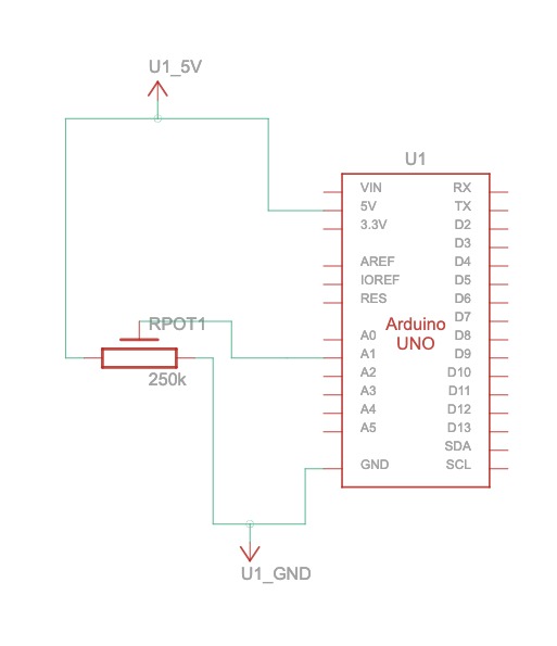
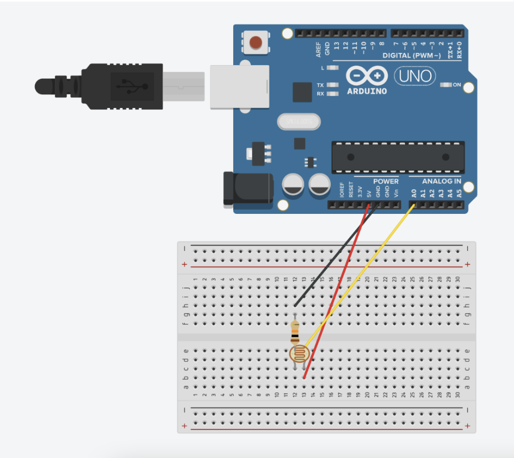
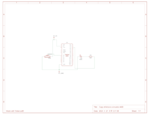
To complete this exercise, we built a simple circuit as illustrated below. We used the photocell to control the horizontal movement of the ball in p5.

Exercise 1 Illustration

As it is shown in the code for Arduino, most of it is similar to that of the one provided to the class. The things we changed are mostly done inside the void loop(). Since the Arduino is sending information to p5, we readjusted the code so that data is sent unidirectionally to p5: the value collected in A0 from the photocell is sent to p5.

Arduino code:

int leftLedPin = 2;
int rightLedPin = 5;


void setup() {
 // Start serial communication so we can send data
 // over the USB connection to our p5js sketch
 Serial.begin(9600);


 // We'll use the builtin LED as a status output.
 // We can't use the serial monitor since the serial connection is
 // used to communicate to p5js and only one application on the computer
 // can use a serial port at once.
 pinMode(LED_BUILTIN, OUTPUT);


 // Outputs on these pins
 pinMode(leftLedPin, OUTPUT);
 pinMode(rightLedPin, OUTPUT);


 // Blink them so we can check the wiring
 digitalWrite(leftLedPin, HIGH);
 digitalWrite(rightLedPin, HIGH);
 delay(200);
 digitalWrite(leftLedPin, LOW);
 digitalWrite(rightLedPin, LOW);


 // start the handshake
 while (Serial.available() <= 0) {
   digitalWrite(LED_BUILTIN, HIGH); // on/blink while waiting for serial data
   Serial.println("0,0"); // send a starting message
   delay(300);            // wait 1/3 second
   digitalWrite(LED_BUILTIN, LOW);
   delay(50);
 }
}


void loop() {
 // wait for data from p5 before doing something
     int sensor = analogRead(A0);
     delay(5);
     Serial.println(sensor);
 }

On p5, we drew an ellipse and initialized a variable ‘xposition’ that is used to move the horizontal position of the ball. Then under ‘if (data != null) {}’, we set the xposition = data where data refers to the value that is collected and sent from Arduino. This data is used to change the xposition of the ball in p5. 

p5 code:

let rVal = 0;
let alpha = 255;
let xposition = 100;


function setup() {
  createCanvas(640, 480);
  textSize(18);
}


function draw() {
  // one value from Arduino controls the background's red color
  background(map(rVal, 0, 1023, 0, 255), 255, 200);


  ellipse(xposition, height/2, 50, 50);
  
  // the other value controls the text's transparency value
  fill(255, 0, 255, map(alpha, 0, 1023, 0, 255));


  if (!serialActive) {
    text("Press Space Bar to select Serial Port", 20, 30);
  } else {
    text("Connected", 20, 30);
    // Print the current values
    text('rVal = ' + str(rVal), 20, 50);
    text('alpha = ' + str(alpha), 20, 70);
  }


function keyPressed() {
  if (key == " ") {
    // important to have in order to start the serial connection!!
    setUpSerial();
  }
}


// This function will be called by the web-serial library
// with each new *line* of data. The serial library reads
// the data until the newline and then gives it to us through
// this callback function
function readSerial(data) {
  ////////////////////////////////////
  //READ FROM ARDUINO HERE
  ////////////////////////////////////


  if (data != null) {
    // make sure there is actually a message
    // split the message
    xposition = data;
    }


    //////////////////////////////////
    //SEND TO ARDUINO HERE (handshake)
    //////////////////////////////////
    let sendToArduino = left + "," + right + "\n";
    writeSerial(sendToArduino);
  }

EXERCISE 02: P5 TO ARDUINO COMMUNICATION: Make something that controls the LED brightness from p5.

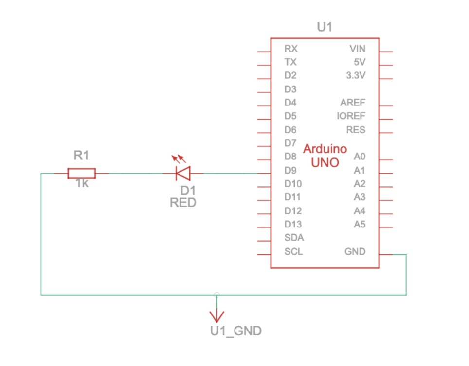
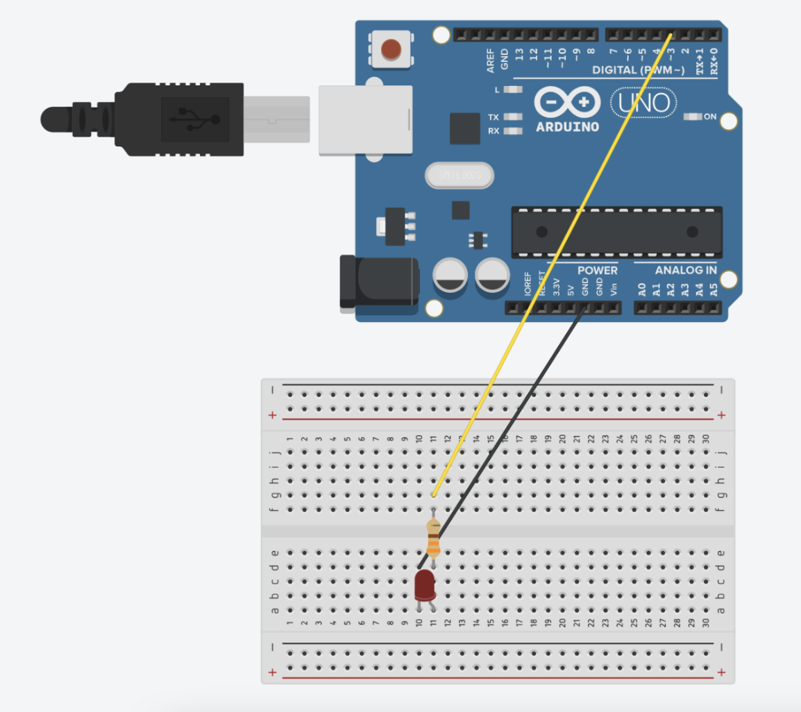
For this exercise, we utilized the position of mouseX from p5 to control the brightness of the LED on Arduino. The circuit we made looks like this: 

circuit 2

Exercise 2 Illustration

Here, Arduino receives information from p5 and changes the brightness of the LED. Under void loop(), we used the map function to convert the values to PWM range and used analogWrite to set the LED brightness according to the value received from p5. 

Arduino Code:

int LEDpin = 3;  // Ensure this pin supports PWM
void setup() {
 Serial.begin(9600);
 pinMode(LED_BUILTIN, OUTPUT);
 pinMode(LEDpin, OUTPUT);


 // Initial blink to confirm working setup
 digitalWrite(LEDpin, HIGH);
 delay(200);
 digitalWrite(LEDpin, LOW);


 // Wait for initial data before proceeding
 while (Serial.available() <= 0) {
   digitalWrite(LED_BUILTIN, HIGH);  // Blink LED to indicate waiting for connection
   Serial.println("0,0");  // Send a starting message
   delay(300);
   digitalWrite(LED_BUILTIN, LOW);
   delay(50);
 }
}


void loop() {
 if (Serial.available() > 0) {
   digitalWrite(LED_BUILTIN, HIGH);  // LED on while receiving data
   int bright = Serial.parseInt();
   bright = map(bright, 0, 640, 0, 255);  // Adjust received value to PWM range


   if (Serial.read() == '\n') {
     analogWrite(LEDpin, bright);  // Set LED brightness
   }
   digitalWrite(LED_BUILTIN, LOW);  // Turn off status LED after handling data
   Serial.println(0);
 }
}

In p5, we used mouseX and its position on the canvas to control the brightness of the LED on Arduino. We initialized a variable LEDbright to 0 but then let it change according to the if statement. If mouseX <= width && mouseX >= 0 && mouseY <= height && mouseY >= 0 , then the variable LEDbright is mouseX and this data is then sent to Arduino which controls the brightness of the LED. However, if the condition is not satisfied, then the variable LEDbright remains 0. Simply put, the LED lights up brighter when the mouse is on the right side of the screen and dimmer when it is on the left side of the screen. 

p5 code:

let LEDbright = 0;

function setup() {
  createCanvas(640, 480);
  textSize(18);
}

function draw() {
  
  background(205);

  // the other value controls the text's transparency value
  fill(0)

  if (!serialActive) {
    text("Press Space Bar to select Serial Port", 20, 30);
  } else {
    text("Connected", 20, 30);

  }

  // when clicked, digital LED will turn on,
  // other analog write LED will have brightness corresponding to the height of the mouse when it is press. can be pressed and dragged for controlling brightness
  if (mouseX <= width && mouseX >= 0 && mouseY <= height && mouseY >= 0) {
      LEDbright = mouseX;
  } else {
    LEDbright = 0;
  }
}

function keyPressed() {
  if (key == " ") {
    // important to have in order to start the serial connection!!
    setUpSerial();
  }
}

function readSerial(data) {
  ////////////////////////////////////
  //READ FROM ARDUINO HERE
  ////////////////////////////////////

    //////////////////////////////////
    //SEND TO ARDUINO HERE (handshake)
    //////////////////////////////////
    
    //send the posiiton of mouseY when clicked to control brightness
    let sendToArduino = LEDbright + "\n";
    writeSerial(sendToArduino);

}

EXERCISE 03: BI-DIRECTIONAL COMMUNICATION: Take the gravity wind example and make it so: every time the ball bounces one led lights up and then turns off, and you can control the wind from one analog sensor.

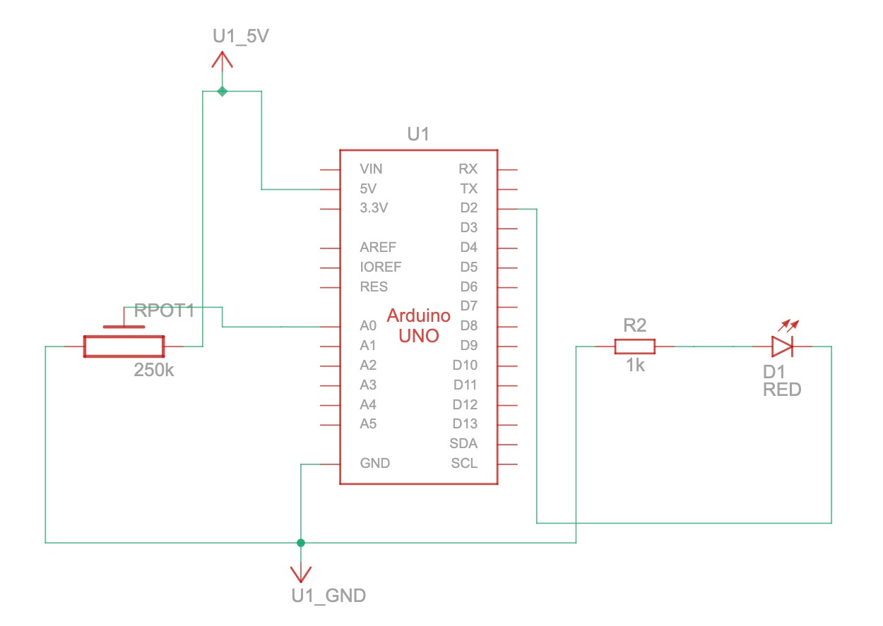
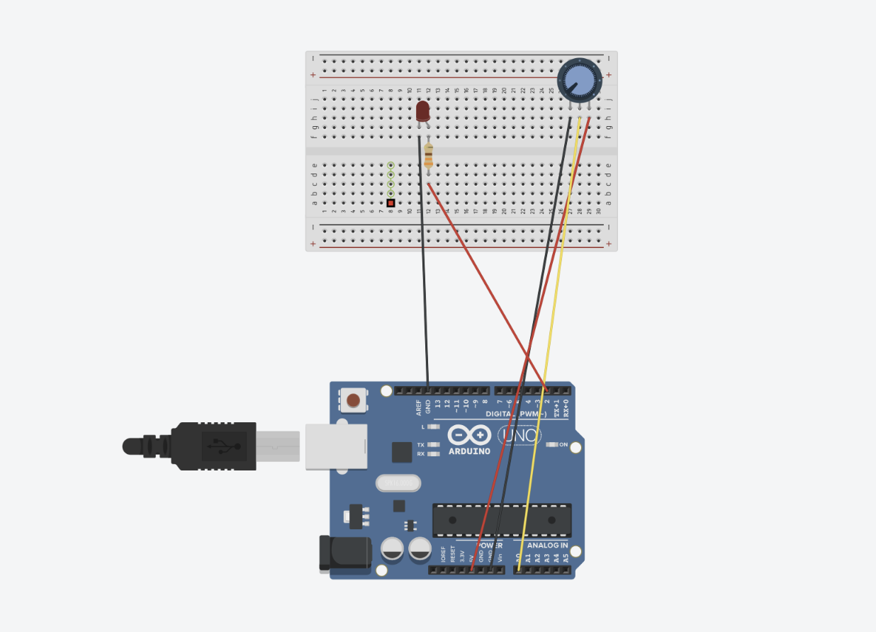
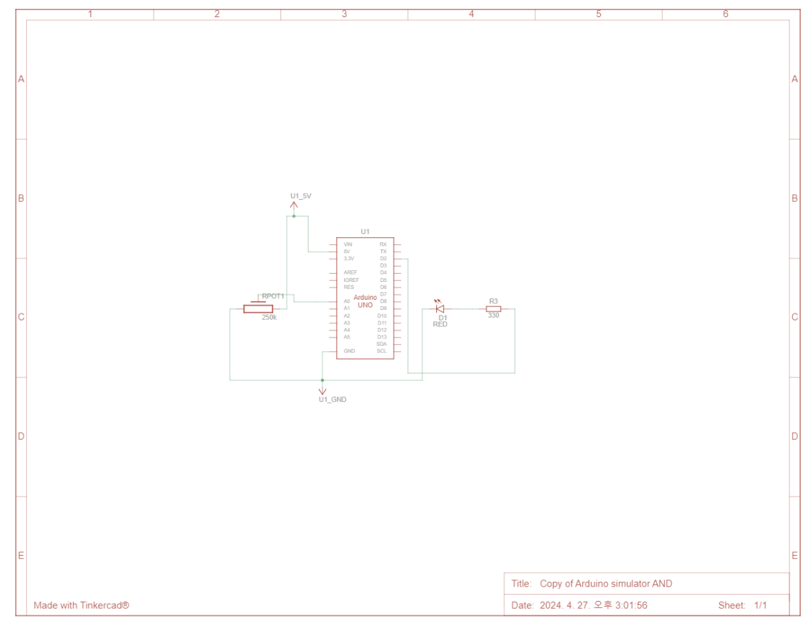
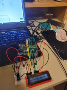
To complete this assignment, we used a potentiometer as an input to control wind and an LED as an output controlled by the bouncing ball in p5.js.

Exercise 3 Illustration

p5 code:

let velocity;
let gravity;
let position;
let acceleration;
let wind;
let drag = 0.99;
let mass = 50;
let light = 0;

function setup() {
  createCanvas(640, 360);
  noFill();
  position = createVector(width/2, 0);
  velocity = createVector(0,0);
  acceleration = createVector(0,0);
  gravity = createVector(0, 0.5*mass);
  wind = createVector(0,0);
}

function draw() {
  background(255);
  applyForce(wind);
  applyForce(gravity);
  velocity.add(acceleration);
  velocity.mult(drag);
  position.add(velocity);
  acceleration.mult(0);
  fill('black')
  
   if (!serialActive) {
    text("Press Space Bar to select Serial Port", 20, 30);
  } else {
    ellipse(position.x,position.y,mass,mass);
  if (position.y > height-mass/2) {
      velocity.y *= -0.9;  // A little dampening when hitting the bottom
      position.y = height-mass/2;
    light=1
    
    }
    else{
      light=0
    }
  }
}

function applyForce(force){
  // Newton's 2nd law: F = M * A
  // or A = F / M
  let f = p5.Vector.div(force, mass);
  acceleration.add(f);
}

function keyPressed() {
  if (key == " ") {
    // important to have in order to start the serial connection!!
    setUpSerial();
  }
}


function readSerial(data) {
  ////////////////////////////////////
  //READ FROM ARDUINO HERE
  ////////////////////////////////////

  if (data != null) {
    // make sure there is actually a message
    // split the message
    let fromArduino = split(trim(data), ",");
    // if the right length, then proceed
    if (fromArduino.length == 1) {
      // only store values here
      // do everything with those values in the main draw loop
      
      // We take the string we get from Arduino and explicitly
      // convert it to a number by using int()
      // e.g. "103" becomes 103
      
      let sensorValue = int(fromArduino[0]);
      wind.x = map(sensorValue, 0, 1023, -1, 1);
    }
    }
    

    //////////////////////////////////
    //SEND TO ARDUINO HERE (handshake)
    //////////////////////////////////
    let sendToArduino = light + "\n";
    writeSerial(sendToArduino);
  }

Arduino code:

int LEDpin = 2;
int wind = A0;

void setup() {
  // Start serial communication so we can send data
  // over the USB connection to our p5js sketch
  Serial.begin(9600);

  // We'll use the builtin LED as a status output.
  // We can't use the serial monitor since the serial connection is
  // used to communicate to p5js and only one application on the computer
  // can use a serial port at once.
  pinMode(LED_BUILTIN, OUTPUT);

  // Outputs on these pins
  pinMode(LEDpin, OUTPUT);
  pinMode(wind, INPUT);


  // start the handshake
  while (Serial.available() <= 0) {
    digitalWrite(LED_BUILTIN, HIGH); // on/blink while waiting for serial data
    Serial.println("0,0"); // send a starting message
  }
}

void loop() {
  // wait for data from p5 before doing something
  while (Serial.available()) {
    digitalWrite(LED_BUILTIN, HIGH); // led on while receiving data

    int light = Serial.parseInt();
    if (Serial.read() == '\n') {
      digitalWrite(LEDpin, light);
      int sensor = analogRead(A0);
      delay(5);
      Serial.println(sensor);
    }
  }
  digitalWrite(LED_BUILTIN, LOW);
}

To briefly explain this code, every time the ball hits the ground, the variable ‘light’ is set to 1. If this is not the case, ‘light’ is set to 0.

if (!serialActive) {
    text("Press Space Bar to select Serial Port", 20, 30);
  } else {
    ellipse(position.x,position.y,mass,mass);
  if (position.y > height-mass/2) {
      velocity.y *= -0.9;  // A little dampening when hitting the bottom
      position.y = height-mass/2;
    light=1
    
    }
    else{
      light=0
    }
  }
}

Then, p5.js sends the value of ‘light’ to the Arduino.

let sendToArduino = light + "\n";
    writeSerial(sendToArduino);

When the Arduino receives the light value from p5.js, it turns on if the value is 1 and turns off if the value equals 0.

int light = Serial.parseInt();
    if (Serial.read() == '\n') {
      digitalWrite(LEDpin, light);

To control the wind value, if the length of the data sensed by the Arduino is equal to 1, p5.js receives the data value of the potentiometer. We then use the map function to convert the analog input value from 0 to 1023 to a range of -1 to 1.

if (data != null) {
   // make sure there is actually a message
   // split the message
   let fromArduino = split(trim(data), ",");
   // if the right length, then proceed
   if (fromArduino.length == 1) {
     // only store values here
     // do everything with those values in the main draw loop
     
     // We take the string we get from Arduino and explicitly
     // convert it to a number by using int()
     // e.g. "103" becomes 103
     
     let sensorValue = int(fromArduino[0]);
     wind.x = map(sensorValue, 0, 1023, -1, 1);
   }
   }


Reading Reflection: Week 12

The author gave the market of eyewear as an example in which fashion and disability overlap. As a user of glasses, I used to think that wearing glasses was unfashionable and hence, in a broader sense, thought that disability and fashion were two separate things. However, nowadays, with emphasis on fashion and appearances, disability goes well along with fashion. Therefore, people with bad eyesight look for glasses that not only provide vision but also style. In this way, customers in the eyewear market do not have to stress about giving up either vision or fashion. Furthermore, the eyewear market has expanded so much to the point where people without vision disability wear glasses for fashion. The term “fashion glasses” is used to identify products in the eyewear market that are intended to attract customers who wish to buy glasses for fashion. I think the eyewear market is a great example that shows how incorporating both fashion and disability not only benefits the producers by maximizing their profit but also the customers who obtain clear vision and style. 

Innovating designs for people with disability pushes people to develop various skills. Hearing aid devices, for instance, are being designed for disability where discretion is still a priority. Therefore, many designs try to conceal the devices or make them invisible when in use. Technological miniaturization is constantly used to make devices invisible for the user’s comfort. In this way, in an attempt to create designs for people with disability, technological advancements can be made and new skills can be obtained. One downside, however, of technological advancement is that it is often costly. Therefore, extra effort and time must be invested to bring out the best in the process.

In short, the reading made me realize the embracement of fashion. Fashion designers collaborate with designers who create products for people with disability to allow customers to enjoy comfort and style. Through the exploration of developing designs, new skills and technological advancements can be obtained which is good for both the producers and consumers. The reading helped me appreciate the developments that does not force me to give up one over the other and helped me realize that we can get a hold on both.