Luke Nguyen – Week 12 Reading Reflection

I agree with the point that there is a contention between designing for disability and fashion. After all, designing for disability is all about functionality and fashion/aesthetics should be considered a complementary part. However, I do think that sometimes fashion/aesthetics does have to be taken into account. Our lives are highly driven by shame and embarrassment, mostly because of internalized unpleasant experience regarding how we are seen by other people, so sometimes technology designed for disability has to serve a good luck to boost the wearers’ confidence. I don’t completely agree that we should incorporate the “spectacle design” into disability product as the author argues, because this contention I think depends on the type of product and its potential users.

In terms of weather the design should be universal or not, I think that universality should be a more a desirable achievement than a compulsory mission. If the goal can be achieved, then it’s laudable. Universality doesn’t have to be too complicated to cover a wide range of disabilities. The iPhone, and its peer iPod, is a very epitomic example. Such design with compact features successfully serve mostly everybody. Before the birth of the iPhone, nobody really thought almost every aspect of their lives could be condensed into one device until such a device was created. Nevertheless, if we treat universality as a mission then the amount of the design work necessary might not be worth it.

The level of accessibility and the quality of life is increasing. People have access to more and more well-designed devices that serve their needs; once they have used up all the features that satisfy their needs, there is no point for them to use those that don’t. In other words, users might not use, or even bring themselves to use, every feature available in their gadgets these days. Still, despite this, manufacturers have been competing with one another to provide a centralized experience to their users with their multimodal products, so we are moving towards such future either way. And they succeed in encouraging consumerism with successful and strategic marketing. People rush to buy devices that are promoted to serve in multi-facets but only utilize a few facets.

W12- Final Project Draft 1

Concept:

I have always been interested in the complexity of human emotion and humanness in different art forms. For my final project, I have chosen to delve deeper into my interest by exploring the concept of humanness through the integration of technology and art. Central to this exploration is the utilization of a pulse sensor, a device capable of detecting heartbeats in real-time. I intend for the pulse sensor to serve as a bridge between the physical digital digital worlds, which can help me capture the intimate and raw rhythms of the human heart, reflecting the concept I want to bring to life. By using physiological data, I aim to create a dynamic and interactive experience using the p5js canvas as my medium to display it. To add to the interactive and immersive experience I am trying to create, I want to add a piezo buzzer to create noise as the user moves the mouse horizontally across the canvas. These different noises can help cultivate a deeper immersive experience for users. Therefore, the main vision for my project is to craft an immersive experience where users not only witness but engage with the essence of human emotion through visual art, color, and sound. 

Example-

Like how the person in the image is moving the interactive are piece with his hands, facilitating movement, I want to create a digital form of something similar where users can move their mouse horizontally to create dynamic movement just like in the image.

Design and Description of Arduino and P5 Program:

The Arduino program will mainly be responsible for receiving data from the pulse sensor via serial communication with the P5 program. Meanwhile, the P5 program will create an interactive visualization using the data received from the pulse sensor. The addition of a piezo buzzer adds another layer of sensory engagement, immersing users deeper into the experience. The buzzer will create various noises utilizing the horizontal position of the mouse on the P5 canvas as data to create sound.  By integrating the functionalities of both Arduino and P5, the project creates a holistic and immersive experience that captivates users and invites them to explore the intricate interplay between humanness, technology, art, and sound.


Luke Nguyen – Final Project Idea – DJ Turntable/Audio Workstation

Updated Sunday April 28:

My final project idea is a DJ Turntable/Audio Workstation that can allow users to input music from Arduino using a special glove into p5 and visualize it. The idea for the project comes from this Mimu glove.

Users can send music notes from Arduino to p5 using different sensors such as pressure sensors, distance sensors, and either an accelerometer or a gyrometer.

Using the pressure sensors attached to the tip of the glove that they wear, users can transfer 7 basic music notes from C to B into p5 by tapping their fingers or tapping on the table?. Simultaneously combining it with a distance sensors placed on the table, they can change the frequency/pitch of the music notes, ranging from B0 to D#8 that Arduino can interpret (if they input the music notes using their fingers then the distance sensor should be placed in a way that can red their hands’ position. Keeping doing that until they have generated something either funky, something following a stream of consciousness, or a nice melody.

In terms of generating rhythm, the users can input rhythm from Arduino to p5 by using the same method, or should I use the accelerometer/gyrometer to sense motion to input the rhythm?

As of now, I’m thinking of having users control all the melody and the rhythm by just utilizing the pressure sensor and the distance sensor as a simple way, or incorporating an accelerometer/gyrometer to measure their wrists’ motion and input their drum as a more advanced way.

These music notes will be recorded, once the p5 don’t detect the users generate the music notes for more than 5/8/10 secs?, it will save the melody and keep looping it. This melody will be visualized. This will apply to the rhythm as well.

Users can input at most 5 melodies/rhythms and have them visualized.

Added Thursday, April 25:

My final project idea is a DJ Turntable that can allow users to control music using Arduino and p5.

Initially my idea is about controlling music with the potentiometer on Arduino but the song mixing will be inside p5 (mixing the melody of one song with the melody of another song).

Users can send music notes from potentiometer inside Arduino to p5, then mix the notes inside p5, and then send it back to Arduino to play.

Professor’s comments:
– Utilize Touch sensor from Arduino, remix songs in p5,

– Make turntable funky on Arduino board with different settings using buttons, sensors, control everything on the Arduino but mix the songs in p5,

– When someone DJ for 5 secs, the LEDs blink up and down like in a club,
– Use flex sensor to change frequency, use pressure sensor to […],

  • Don’t depend on Arduino to play sound

The DJ Turntable will be incorporated with Music Visualizer:
– Send music from Arduino into p5 to visualize in visualizers (maybe galaxy theme like the ones shown in the hallway from decoding nature class?)

– P5 send visualizers back to Arduino to light up the LEDS to light up accordingly to the colors inside the visualizer.

Visualizer in p5 examples:
– Sine and cosine
– How users choose songs
– Maybe frequency change wave, amplitude change colors….

Luke & Gunjan – Assignment 12

Exercise 1:

Circuit:

Code:

P5Js:

//Exercise 1 P5js Code

let ellipseX; // Variable to store ellipse's x-coordinate

function setup() {
  createCanvas(600, 400); // Create a canvas of 800x400 pixels
  ellipseX = width / 2; // Set initial x-coordinate of ellipse to middle of the screen
  noStroke(); // No stroke for the ellipse
}

function draw() {
  
  background(220); // Refresh background on each frame
  fill(0, 0, 255); // Set fill color to red
  ellipse(ellipseX, height / 2, 50, 50); // Draw ellipse at current x-coordinate and middle of the screen
  
  if (!serialActive) {
    text("Press Space Bar to select Serial Port", 20, 30);
  } else {
    text("Connected", 20, 30);}
}


function keyPressed() {
  if (key == " ") {
    // important to have in order to start the serial connection!!
    setUpSerial();
  }   
}

// this callback function
function readSerial(data) {
  ////////////////////////////////////
  //READ FROM ARDUINO HERE
  ////////////////////////////////////

  if (data != null) {
    // make sure there is actually a message
    // split the message
   
    let fromArduino = split(trim(data), ",");
    // if the right length, then proceed
    if (fromArduino.length == 1) {
      // only store values here
      // do everything with those values in the main draw loop
//values from light sensor roughly ranged between 0 and 500,000 so map them between 0 and width of the screen
//use the mapped value as x-coordinate of the ellipse
      ellipseX = map(data,0,500000, 0,width);
    }

    //////////////////////////////////
    //SEND TO ARDUINO HERE (handshake)
    //////////////////////////////////
   let sendToArduino = fromArduino + "\n";
   writeSerial(sendToArduino);
  }
}

Arduino codes:

//Exercise 1 Arduino Code 

void setup() {
  Serial.begin(9600); // Start serial communication at 9600 bps

  pinMode(LED_BUILTIN, OUTPUT);
// start the handshake
  while (Serial.available() <= 0) {
    //digitalWrite(LED_BUILTIN, HIGH); // on/blink while waiting for serial data
    Serial.println("0,0"); // send a starting message
    delay(300);            // wait 1/3 second
    //digitalWrite(LED_BUILTIN, LOW);
    delay(50);
  }
}
void loop() {

  // wait for data from p5 before doing something
    while (Serial.available()) {
    digitalWrite(LED_BUILTIN, HIGH); // led on while receiving data

  // Read sensor value
  int sensorValue = analogRead(A0);
   Serial.print(sensorValue);
  // Map sensor value to screen width 
  int screenValue = map(sensorValue, 0, 1023, 0, 600);

  // Send mapped value to p5.js
  Serial.println(screenValue);

  delay(50); //    for stability
}
digitalWrite(LED_BUILTIN, LOW);
}

In future implementations, we may want the ball to move in a smoother fashion. We can consider adding codes that can smooth out the path of the ball’s movement. But using the photosensor to control the ball, we reinforce the knowledge about coding in Arduino and sending data from Arduino to p5.

Exercise 2:
Circuit:

P5js code:

let rVal = 0;
let alpha = 255;
let left = 0; // True (1) if mouse is being clicked on left side of screen
let right = 0; // True (1) if mouse is being clicked on right side of screen
let slider;

function setup() {
  createCanvas(640, 480);
  textSize(18);
  slider = createSlider(0,255,0);
  slider.position(50,50);
}

function draw() {
  // one value from Arduino controls the background's red color
  background('white');

  // if (!serialActive) {
    text("Press Space Bar to select Serial Port", 20, 30);
  // } else {
  //   text("Connected", 20, 30);
  //   // Print the current values
    // text('rVal = ' + str(rVal), 20, 50);
  //   text('alpha = ' + str(alpha), 20, 70);
  // }


  // click on one side of the screen, one LED will light up
  // click on the other side, the other LED will light up
  // if (mouseIsPressed) {
  //   if (mouseX <= width / 2) {
  //     left = 1;
  //   } else {
  //     right = 1;
  //   }
  // } else {
  //   left = right = 0;
  // }
}

function keyPressed() {
  if (key == " ") {
    // important to have in order to start the serial connection!!
    setUpSerial();
  }
}

// This function will be called by the web-serial library
// with each new *line* of data. The serial library reads
// the data until the newline and then gives it to us through
// this callback function
function readSerial(data) {
  ////////////////////////////////////
  //READ FROM ARDUINO HERE
  ////////////////////////////////////

  if (data != null) {
    //////////////////////////////////
    //SEND TO ARDUINO HERE (handshake)
    //////////////////////////////////
    let sendToArduino = slider.value() + "\n";
    console.log(slider.value());
    writeSerial(sendToArduino);
    
    }

}

Arduino code:

int rightLedPin = 5;
int brightness = 0;

void setup() {
  // Start serial communication so we can send data
  // over the USB connection to our p5js sketch
  Serial.begin(9600);

  // We'll use the builtin LED as a status output.
  // We can't use the serial monitor since the serial connection is
  // used to communicate to p5js and only one application on the computer
  // can use a serial port at once.
  pinMode(LED_BUILTIN, OUTPUT);

  // Outputs on these pins
  // pinMode(leftLedPin, OUTPUT);
  pinMode(rightLedPin, OUTPUT);

  // Blink them so we can check the wiring
  // digitalWrite(leftLedPin, HIGH);
  digitalWrite(rightLedPin, HIGH);
  delay(200);
  // digitalWrite(leftLedPin, LOW);
  digitalWrite(rightLedPin, LOW);


  // start the handshake
  while (Serial.available() <= 0) {
    digitalWrite(LED_BUILTIN, HIGH); // on/blink while waiting for serial data
    Serial.println("0,0"); // send a starting message
    delay(300);            // wait 1/3 second
    digitalWrite(LED_BUILTIN, LOW);
    delay(50);
  }
}

void loop() {
  // wait for data from p5 before doing something
  while (Serial.available()) {
    digitalWrite(LED_BUILTIN, HIGH); // led on while receiving data

    // int left = Serial.parseInt();
    int right = Serial.parseInt();
    if (Serial.read() == '\n') {
      // digitalWrite(leftLedPin, left);
      analogWrite(rightLedPin, right);
      
      
      // int sensor = analogRead(A0);
      // delay(5);
      // int sensor2 = analogRead(A1);
      // delay(5);
      // Serial.print(sensor);
      // Serial.print(',');
      Serial.println();
    }
  }
  digitalWrite(LED_BUILTIN, LOW);

}

In terms of the future improvement for this one, we may want to control multiple LEDs with only one slider, or add more sliders to control many LEDs. But it helped us think about writing the code on transferring data to Arduino.

Exercise 3:
Circuit:Code:

p5js code:

let velocity;
let gravity;
let position;
let acceleration;
let wind;
let drag = 0.99;
let mass = 50;
let rVal ;

function setup() {
  createCanvas(640, 360);
  noFill();
  position = createVector(width/2, 0);
  velocity = createVector(0,0);
  acceleration = createVector(0,0);
  gravity = createVector(0, 0.5*mass);
  wind = createVector(0,0);
}

function draw() {
  background(255);
  applyForce(wind);
  applyForce(gravity);
  velocity.add(acceleration);
  velocity.mult(drag);
  position.add(velocity);
  acceleration.mult(0);
  fill("blue");
  ellipse(position.x,position.y,mass,mass);
  if (position.y > height-mass/2) {
      velocity.y *= -0.9;  // A little dampening when hitting the bottom
      position.y = height-mass/2;
    }
  if (position.y == height - mass/2) {
      right = 1;
  } else {
      right = 0;
  }
  if (rVal > 522) {
    wind.x = 1;
} else if (rVal < 502) {
    wind.x = -1;
} else {
    wind.x = 0;
}

  
  // if (!serialActive) {
  //   text("Press Space Bar to select Serial Port", 20, 30);
  // } else {
  //   text("Connected", 20, 30);
  //   // Print the current values
  //   text('rVal = ' + str(rVal), 20, 50);
  //   text('alpha = ' + str(alpha), 20, 70);
  // }
}

function applyForce(force){
  // Newton's 2nd law: F = M * A
  // or A = F / M
  let f = p5.Vector.div(force, mass);
  acceleration.add(f);
}

// if (position.y == height - mass/2) {
    
//     //   left = 1;
//     // } else {
//       right = 1;
//     // }
//   } else {
//     // left = right = 0;
//   right = 0;
//   }

function keyPressed(){
  if (key == " ") {
    // important to have in order to start the serial connection!!
    setUpSerial();
  }
  // if (keyCode==LEFT_ARROW){
  //   wind.x=-1;
  // }
  // if (keyCode==RIGHT_ARROW){
  //   wind.x=1;
  // }
  if (keyCode==ENTER){
    // mass=random(15,80);
    position.y=-mass;
    velocity.mult(0);
  }
}

function readSerial(data) {
  ////////////////////////////////////
  //READ FROM ARDUINO HERE
  ////////////////////////////////////

  if (data != null) {
    // make sure there is actually a message
    // split the me ssage
    rVal=data;
    print(rVal);

    //////////////////////////////////
    //SEND TO ARDUINO HERE (handshake)
    //////////////////////////////////
    let sendToArduino = right + "\n";
    writeSerial(sendToArduino);
  }
}

Arduino code:

// Week 11.2 Example of bidirectional serial communication

// Inputs:
// - A0 - sensor connected as voltage divider (e.g. potentiometer or light sensor)
// - A1 - sensor connected as voltage divider 
//
// Outputs:
// - 2 - LED
// - 5 - LED

// int leftLedPin = 2;
int rightLedPin = 5;

void setup() {
  // Start serial communication so we can send data
  // over the USB connection to our p5js sketch
  Serial.begin(9600);

  // We'll use the builtin LED as a status output.
  // We can't use the serial monitor since the serial connection is
  // used to communicate to p5js and only one application on the computer
  // can use a serial port at once.
  pinMode(LED_BUILTIN, OUTPUT);

  // Outputs on these pins
  // pinMode(leftLedPin, OUTPUT);
  pinMode(rightLedPin, OUTPUT);

  // Blink them so we can check the wiring
  // digitalWrite(leftLedPin, HIGH);
  digitalWrite(rightLedPin, HIGH);
  delay(200);
  // digitalWrite(leftLedPin, LOW);
  digitalWrite(rightLedPin, LOW);


  // start the handshake
  while (Serial.available() <= 0) {
    digitalWrite(LED_BUILTIN, HIGH); // on/blink while waiting for serial data
    Serial.println("0,0"); // send a starting message
    delay(300);            // wait 1/3 second
    digitalWrite(LED_BUILTIN, LOW);
    delay(50);
  }
}

void loop() {
  // wait for data from p5 before doing something
  while (Serial.available()) {
    digitalWrite(LED_BUILTIN, HIGH); // led on while receiving data

    // int left = Serial.parseInt();
    int right = Serial.parseInt();
    if (Serial.read() == '\n') {
      // digitalWrite(leftLedPin, left);
      digitalWrite(rightLedPin, right);
      // int sensor = analogRead(A0);
      // delay(5);
      int sensor2 = analogRead(A1);
      delay(5);
      // Serial.print(sensor);
      // Serial.print(',');
      Serial.println(sensor2);
    }
  }
  digitalWrite(LED_BUILTIN, LOW);
}

Challenges and implementations: we had no problem making the LED blink every time the ball touches the ground. But we did face some challenges in controlling the wind with the potentiometer initially. The ball kept moving to the left and we couldn’t figure out how to control it no matter what. In the end, we figure out that the issue lies in mapping and in coding the snippets of codes we want to send from p5 into Arduino. For improvements, we want to increase the speed of the ball being controlled by the potentiometer. At the moment, it is moving rather slowly.

Week 12 – Exercises – Linh and Sihyun

Exercise 1:

Link to the video: https://youtube.com/shorts/4ek33gKQaNY?si=3ArQyArCtsPfHlGx

P5 sketch:

p5.js Code:

let xposition = 100;
function setup() {
  createCanvas(640, 480);
  textSize(18);
}
function draw() {
  background(0, 255, 0);
  fill(0);
  ellipse(xposition, height / 2, 50, 50);
}

function keyPressed() {
  if (key == " ") {
    // Calls a function to set up the serial connection
    setUpSerial();
  }
}

// Function to read data from the serial port
function readSerial(data) {
  // Check if data received is not null
  if (data != null) {
    // Maps the integer value of data from range 0-1023 to 0-640 and updates xposition
    xposition = map(int(data), 0, 1023, 0, 640);
  }
}

Arduino Code:

void setup() {
  // Start serial communication so we can send data
  // over the USB connection to our p5js sketch
  Serial.begin(9600);
}

void loop() {


      int sensor = analogRead(A0);
      delay(5);
      Serial.println(sensor);
 
}

Circuit:

For this exercise, we have utilized the potentiometer to change the position of the ellipse in the p5.js sketch. As shown in the code snippet, the ellipse’s x position is mapped to the value of the potentiometer from the Arduino. First of all, by calling the setUpSerial() function when the space bar is pressed, the p5.js sets up the serial connection with the Arduino. Then, using the readSerial(data) the p5.js reads data regarding the potentiometer value from the Arduino.

For the Arduino, we used Serial. begin(9600) to start the serial communication. Inside the loop function, we have Serial.println(sensor) to send the sensor value to the serial port as a line of text (string), ending in a newline character.

Exercise 2:

Video:

P5 sketch:

P5.js code

In the p5 code, the mouseX is used to control the brightness of the LED light. MouseX is mapped from 0 to width of the canvas to 0 to 255. Utilizing the function readSerial(), we send the value of the mapped mouseX to the Arduino using the below line of codes:

function readSerial(data) {

  if (data != null) {
    //////////////////////////////////
    //SEND TO ARDUINO HERE (handshake)
    //////////////////////////////////
    let sendToArduino = left + "\n";
    writeSerial(sendToArduino);
  }
}

Arduino Code

In the Arduino code, after the initial handshake, the code continuously checks for any data that is sent from the Arduino code. It then parses the sending string and uses that string to control the brightness of the LED using analogWrite. The value has been mapped to the range of 255 so there is no need of mapping again in the Arduino code.

int leftLedPin = 3;


void setup() {
  // Start serial communication so we can send data
  // over the USB connection to our p5js sketch
  Serial.begin(9600);


  // We'll use the builtin LED as a status output.
  // We can't use the serial monitor since the serial connection is
  // used to communicate to p5js and only one application on the computer
  // can use a serial port at once.
  pinMode(LED_BUILTIN, OUTPUT);


  // Outputs on these pins
  pinMode(leftLedPin, OUTPUT);


  // Blink them so we can check the wiring
  digitalWrite(leftLedPin, HIGH);
  delay(200);
  digitalWrite(leftLedPin, LOW);


  // start the handshake
  while (Serial.available() <= 0) {
    digitalWrite(LED_BUILTIN, HIGH); // on/blink while waiting for serial data
    Serial.println("0,0"); // send a starting message
    delay(300);            // wait 1/3 second
    digitalWrite(LED_BUILTIN, LOW);
    delay(50);
  }
}


void loop() {
  // wait for data from p5 before doing something
  while (Serial.available()) {
    digitalWrite(LED_BUILTIN, HIGH); // led on while receiving data


    int left = Serial.parseInt();
    // int right = Serial.parseInt();
    if (Serial.read() == '\n') {
      analogWrite(leftLedPin, left);
      Serial.println();
    }
  }
  digitalWrite(LED_BUILTIN, LOW);
}

Circuit

Exercise 3

Video:

P5.js Sketch

For the LED to light up every bounce, we assigned a flag “ground”. Every time the ball hits the ground, we set ground = true else it equals to false.

if (position.y > height-mass/2) {
    velocity.y *= -0.9;  // A little dampening when hitting the bottom
    position.y = height-mass/2;
  ground = true;
  }
else{
  ground = false;
}

If ground = true, we will send to Arduino the value of 1, else, we will send 0. We did this because we only use digitalWrite in Arduino which only accepts LOW (0) and HIGH (1) as its value.

if (ground) {
     sendToArduino = "1"+"\n";
    }
    else{
       sendToArduino = "0"+"\n";
    }

For the control of the wind, we used the potentiometer to change the value of the wind. Since there is only one data coming from the Arduino, we didn’t use the trim to parse the function. Instead, we directly map the receiving data to the wind value:

wind.x= map(int(data), 0,1023,-1, 1);

Arduino Code:

int ledPin = 8;


void setup() {
 // Start serial communication so we can send data
 // over the USB connection to our p5js sketch
 Serial.begin(9600);


 // We'll use the builtin LED as a status output.
 // We can't use the serial monitor since the serial connection is
 // used to communicate to p5js and only one application on the computer
 // can use a serial port at once.
 pinMode(LED_BUILTIN, OUTPUT);


 // Outputs on these pins
 pinMode(ledPin, OUTPUT);


 // Blink them so we can check the wiring
 digitalWrite(ledPin, HIGH);
 delay(200);
 digitalWrite(ledPin, LOW);


 // start the handshake
 while (Serial.available() <= 0) {
   digitalWrite(LED_BUILTIN, HIGH); // on/blink while waiting for serial data
   Serial.println("0,0"); // send a starting message
   delay(300);            // wait 1/3 second
   digitalWrite(LED_BUILTIN, LOW);
   delay(50);
 }
}


void loop() {
 // wait for data from p5 before doing something
 while (Serial.available()) {
   digitalWrite(LED_BUILTIN, HIGH); // led on while receiving data


   int led = Serial.parseInt();
   if (Serial.read() == '\n') {
     digitalWrite(ledPin, led);
     int sensor = analogRead(A5);
     Serial.println(sensor);
   }
 }
 digitalWrite(LED_BUILTIN, LOW);
}

In the Arduino sketch, we initiated serial communication with Serial.begin(9600) within the setup() function to set up data transfer at 9600 bits per second. The ledPin variable is set to 8, corresponding to the pin connected to an LED. We use Serial.available() to check for incoming serial data. Initially, the sketch blinks the LED on pin 8 to verify the correct wiring. When it begins receiving data from the serial port, the built-in LED lights up as a signal of data processing. The received data is then used to control the state or brightness of the LED on pin 8. Additionally, the sketch reads the analog value from pin A5 (connected to a potentiometer) and sends this value back to the p5.js, facilitating a continuous, dynamic interaction between the Arduino hardware and the p5.js.

Circuit:

Reflection:

Initially, we had a bit of a problem understanding how the communication between the p5.js and Arduino works. After spending quite a few investigating the sample code, we identified a few of the differences we had in our code and the sample code that caused our code to not work. We also learnt the mapping of values between the p5.js values and the Arduino values (including both variable resistors and analogWrite ranges).

Week 12: Serial Communication

For this week’s assignment, Aysha and I worked on three different exercises that focused on serial communication.

Exercise 1: Moving p5.js ball with potentiometer

p5.js code:

//Variable to declare the ellipse moving acorss the x-axis
let ellipseX;

function setup() {
  //Canvas dimensions
  createCanvas(400, 400);
  //Set text size to 18 pixels
  textSize(18);
  //Initializes ellipse to half the width of the canvas, essentially centers it
  ellipseX = width/2; 
}

function draw() {
  //Sets background to a light purple shade
  background("rgb(185,185,228)");
   // SetS fill color for the ellipse
  fill("rgb(142,142,228)");
  // Sets stroke color/outline for the ellipse
  stroke("rgb(91,91,233)");
  // Draw ellipse at ellipseX position, centered vertically, with a diameter of 120 pixels
  ellipse(ellipseX, height / 2, 120, 120);
  
  // If serial connection is not active, display message to prompt user to select serial port
  if (!serialActive) {
    //Sets fill color to white
    fill('white');
    // Sets stroke color to a gray shade
    stroke('#666666')
     // Display instructions at (15, 30)
    text("Press Space Bar to select Serial Port", 15, 30);
  } 
  // If serial connection is active, display "Connected" message
  else {
    // Display instructions at (15, 30)
    text("Connected", 15, 30);
  }
}

// Function to handle key presses
function keyPressed() {
  // If space bar is pressed, call setUpSerial() function
  if (key == " ") {
    setUpSerial();
  }
}

// Function to read data from the serial port
function readSerial(data) {
  // Check if data is not null
  if (data != null) {
    // Split the received data into an array using comma as delimiter
    let fromArduino = split(trim(data), ",");
    // Map the potentiometer value to adjust the position of the ellipse
    ellipseX = map(int(fromArduino[0]), 0, 1023, 0, width); 
  }
}


Arduino Code:

const int potPin = A1;  // Analog pin connected to the potentiometer
void setup() {
  Serial.begin(9600);
}
void loop() {
    int potValue = analogRead(potPin);  // Read the value from the potentiometer
      // Send the potentiometer value to p5.js
      Serial.println(potValue);
}


Exercise 2: Controlling LED with p5.js slider

p5.js code:

// Variable to hold the brightness value
let brightness = 0;
// Variable to hold the slider
let slider;

function setup() {
  //Canvas dimensions
  createCanvas(400, 400);
  // Create slider with range from 0 to 255 and initial value of 100
  slider = createSlider(0, 255, 100);
  // Positions slider horizontally centered and vertically centered
  slider.position(132, height/2);
}

function draw() {
  // Sets background color to a light gray shade
  background('#ADB9C7');
  // Gets  current value of the slider
  let val = slider.value();
  // Updates brightness variable with the slider value
  brightness = val;
  //If brightness is maximum (255), change background color to light blue
  if (brightness == 255) {
    // Changes background color to gold when brightness is max
    background('#DCECFF');  
  }
  
  // If serial connection is not active, display message to prompt user to select serial port
  if (!serialActive) { 
    // Set fill color to blue
    fill('#0876FF');
    // Set stroke color to a light gray shade
    stroke('#B2B2B2');
    // Set text size to 16 pixels
    textSize(16);
    // Display instructions at (20, 30)
    text("Press Space Bar to select Serial Port", 20, 30);
  } 
  // If serial connection is active, display "Connected" message
  else {
    textSize(16);
    // Display instructions at (29, 30)
    text("Connected",29,30);
  }
}

// Function to handle key presses
function keyPressed() {
   // If space bar is pressed, start the serial connection
  if (key == " ") {
    setUpSerial();  
  }
}

// Function to send data to the serial port
function readSerial(data) {
  // Check if data is not null
  if (data != null) {
    
  //Creates a string to send to Arduino with brightness value followed by newline character (HANDSHAKE)
    let sendToArduino = brightness + "\n";
  // Send data to Arduino
    writeSerial(sendToArduino);
  }
}

Arduino code:

int LED = 5; //PWM PIN
void setup() {
  pinMode(LED, OUTPUT);
  Serial.begin(9600);
  
  
  // initializing handshake
  while (Serial.available() <= 0) {
    Serial.println("Initializing Connection");  
    delay(200);               // wait 1/2 second
  }
}
void loop() {
  // wait for data to load from p5 before continuing code
  while (Serial.available()) {
    int brightness = Serial.parseInt(); 
    if (Serial.read() == '\n') {
      analogWrite(LED, brightness); // turn on LED and adjusts brightness
      Serial.println("ON"); 
    }
  }
}


Exercise 3: Blink LED with bouncing ball and move wind with potentiometer

p5.js code:

let velocity;
let gravity;
let position;
let acceleration;
let wind;
let drag = 0.99;
let mass = 70;

// ball bounce check to control LED
let ballBouncing = 0;

function setup() {
  createCanvas(400, 400);
  textSize(width/25);

  position = createVector(width / 2, 0);
  velocity = createVector(0, 0);
  acceleration = createVector(0, 0);
  gravity = createVector(0, 0.5 * mass);
  wind = createVector(0, 0);
}

function draw() {
  background(210, 230, 250);

  if (!serialActive) {
    text("Press Space Bar to select Serial Port", 20, 30);
  } else {
    applyForce(wind);
    applyForce(gravity);
    velocity.add(acceleration);
    velocity.mult(drag);
    position.add(velocity);
    acceleration.mult(0);
   
 // Check boundaries for right and left movement
    if (position.x > width - mass / 2) {
      position.x = width - mass / 2;
      velocity.x *= -0.9; // Reverse velocity when hitting right boundary
    } else if (position.x < mass / 2) {
      position.x = mass / 2;
      velocity.x *= -0.9; // Reverse velocity when hitting boundary
    }

    ellipse(position.x, position.y, mass, mass);
    if (position.y > height - mass / 2) {
      velocity.y *= -0.9; // A little dampening when hitting the bottom
      position.y = height - mass / 2;
      ballBouncing = 1;
    } else {
      ballBouncing = 0;
    }
  }
}

function keyPressed() {
  if (key == " ") {
    // to start serial connection
    setUpSerial();
  } else if (key == "ENTER") {
    mass = random(15, 80);
    position.y = -mass;
    velocity.mult(0);
  }
}

function readSerial(data) {
  if (data != null) {
    // make sure there is a message and split it
    let fromArduino = split(trim(data), ",");
    // if it's the right length, then proceed
    if (fromArduino.length == 1) {
      // only store values here

      let potentiometerValue = int(fromArduino[0]);
      wind.x = map(potentiometerValue, 0, 1023, -1, 1);
    }

// ARDUINO HANDSHAKE
   
    let sendToArduino = ballBouncing + "\n";
    writeSerial(sendToArduino);
  }
}

function applyForce(force) {
  // Newton's 2nd law: F = M * A
  // or A = F / M
  let f = p5.Vector.div(force, mass);
  acceleration.add(f);
}

Arduino code:

//int ledPin = 5;
//const int potPin=A1;

//void setup() {
  // Start serial communication so we can send data
  // over the USB connection to our p5js sketch
  //Serial.begin(9600);

  //pinMode(LED_BUILTIN, OUTPUT);

  //pinMode(ledPin, OUTPUT);
  //pinMode(potPin, INPUT);


  // start the handshake
  //while (Serial.available() <= 0) {
    //digitalWrite(LED_BUILTIN, HIGH); // on/blink while waiting for serial data
    //Serial.println("0,0"); // send a starting message
    //delay(300);            // wait 1/3 second
    //digitalWrite(LED_BUILTIN, LOW);
    //delay(50);
  //}
//}

//void loop() {
  // wait for data from p5 before doing something
  //while (Serial.available()) {
    //digitalWrite(LED_BUILTIN, HIGH); // led on while receiving data
   //digitalWrite(ledPin, LOW);
   //int ballBouncing =Serial.parseInt();
   
    //if (Serial.read() == '\n') {
    
    //int potPinValue = analogRead(potPin);      delay(5);
      
      //Serial.println(potPinValue);
    //}
  
// Set LED brightness based on whether the ball is bouncing
    //if (ballBouncing == 1) {
      //digitalWrite(ledPin, HIGH);
    //} else {
      //digitalWrite(ledPin, LOW);
    //}
  //}
  //digitalWrite(LED_BUILTIN, LOW);
//}


In Class Exercises by Linh and Sihyun

Exercise 1:

Link to the video: https://youtube.com/shorts/4ek33gKQaNY?si=3ArQyArCtsPfHlGx

P5 sketch: 

p5.js Code:

let xposition = 100;
function setup() {
  createCanvas(640, 480);
  textSize(18);
}
function draw() {
  background(0, 255, 0);
  fill(0);
  ellipse(xposition, height / 2, 50, 50);
}

function keyPressed() {
  if (key == " ") {
    // Calls a function to set up the serial connection
    setUpSerial();
  }
}

// Function to read data from the serial port
function readSerial(data) {
  // Check if data received is not null
  if (data != null) {
    // Maps the integer value of data from range 0-1023 to 0-640 and updates xposition
    xposition = map(int(data), 0, 1023, 0, 640);
  }
}

Arduino Code:

void setup() {
  // Start serial communication so we can send data
  // over the USB connection to our p5js sketch
  Serial.begin(9600);
}

void loop() {


      int sensor = analogRead(A0);
      delay(5);
      Serial.println(sensor);
  
}

Circuit: 

For this exercise, we have utilized the potentiometer to change the position of the ellipse in the p5.js sketch. As shown in the code snippet, the ellipse’s x position is mapped to the value of the potentiometer from the Arduino. First of all, by calling the setUpSerial() function when the space bar is pressed, the p5.js sets up the serial connection with the Arduino. Then, using the readSerial(data) the p5.js reads data regarding the potentiometer value from the Arduino. 

For the Arduino, we used Serial. begin(9600) to start the serial communication. Inside the loop function, we have Serial.println(sensor) to send the sensor value to the serial port as a line of text (string), ending in a newline character.

Exercise 2: 

Video:

 P5 sketch: 

P5.js code

In the p5 code, the mouseX is used to control the brightness of the LED light. MouseX is mapped from 0 to width of the canvas to 0 to 255. Utilizing the function readSerial(), we send the value of the mapped mouseX to the Arduino using the below line of codes:

function readSerial(data) {

  if (data != null) {
    //////////////////////////////////
    //SEND TO ARDUINO HERE (handshake)
    //////////////////////////////////
    let sendToArduino = left + "\n";
    writeSerial(sendToArduino);
  }
}

Arduino Code

In the Arduino code, after the initial handshake, the code continuously checks for any data that is sent from the Arduino code. It then parses the sending string and uses that string to control the brightness of the LED using analogWrite. The value has been mapped to the range of 255 so there is no need of mapping again in the Arduino code.

int leftLedPin = 3;


void setup() {
  // Start serial communication so we can send data
  // over the USB connection to our p5js sketch
  Serial.begin(9600);


  // We'll use the builtin LED as a status output.
  // We can't use the serial monitor since the serial connection is
  // used to communicate to p5js and only one application on the computer
  // can use a serial port at once.
  pinMode(LED_BUILTIN, OUTPUT);


  // Outputs on these pins
  pinMode(leftLedPin, OUTPUT);


  // Blink them so we can check the wiring
  digitalWrite(leftLedPin, HIGH);
  delay(200);
  digitalWrite(leftLedPin, LOW);


  // start the handshake
  while (Serial.available() <= 0) {
    digitalWrite(LED_BUILTIN, HIGH); // on/blink while waiting for serial data
    Serial.println("0,0"); // send a starting message
    delay(300);            // wait 1/3 second
    digitalWrite(LED_BUILTIN, LOW);
    delay(50);
  }
}


void loop() {
  // wait for data from p5 before doing something
  while (Serial.available()) {
    digitalWrite(LED_BUILTIN, HIGH); // led on while receiving data


    int left = Serial.parseInt();
    // int right = Serial.parseInt();
    if (Serial.read() == '\n') {
      analogWrite(leftLedPin, left);
      Serial.println();
    }
  }
  digitalWrite(LED_BUILTIN, LOW);
}

Circuit

Exercise 3

Video:

P5.js Sketch

For the LED to light up every bounce, we assigned a flag “ground”. Everytime the ball hits the ground, we set ground = true else it equals to false.

if (position.y > height-mass/2) {
    velocity.y *= -0.9;  // A little dampening when hitting the bottom
    position.y = height-mass/2;
  ground = true;
  }
else{
  ground = false;
}

If ground = true, we will send to arduino the value of 1, else, we will send 0. We did this because we only use digitalWrite in Arduino which only accepts LOW (0) and HIGH (1) as its value.

if (ground) {
     sendToArduino = "1"+"\n";
    }
    else{
       sendToArduino = "0"+"\n";
    }

For the control of the wind, we used the potentiometer to change the value of the wind. Since there is only one data coming from the Arduino, we didn’t use the trim to parse the function. Instead, we directly map the receiving data to the wind value:

wind.x= map(int(data), 0,1023,-1, 1);

Arduino Code: 

int ledPin = 8;


void setup() {
 // Start serial communication so we can send data
 // over the USB connection to our p5js sketch
 Serial.begin(9600);


 // We'll use the builtin LED as a status output.
 // We can't use the serial monitor since the serial connection is
 // used to communicate to p5js and only one application on the computer
 // can use a serial port at once.
 pinMode(LED_BUILTIN, OUTPUT);


 // Outputs on these pins
 pinMode(ledPin, OUTPUT);


 // Blink them so we can check the wiring
 digitalWrite(ledPin, HIGH);
 delay(200);
 digitalWrite(ledPin, LOW);


 // start the handshake
 while (Serial.available() <= 0) {
   digitalWrite(LED_BUILTIN, HIGH); // on/blink while waiting for serial data
   Serial.println("0,0"); // send a starting message
   delay(300);            // wait 1/3 second
   digitalWrite(LED_BUILTIN, LOW);
   delay(50);
 }
}


void loop() {
 // wait for data from p5 before doing something
 while (Serial.available()) {
   digitalWrite(LED_BUILTIN, HIGH); // led on while receiving data


   int led = Serial.parseInt();
   if (Serial.read() == '\n') {
     digitalWrite(ledPin, led);
     int sensor = analogRead(A5);
     Serial.println(sensor);
   }
 }
 digitalWrite(LED_BUILTIN, LOW);
}

In the Arduino sketch, we initiated serial communication with Serial.begin(9600) within the setup() function to set up data transfer at 9600 bits per second. The ledPin variable is set to 8, corresponding to the pin connected to an LED. We use Serial.available() to check for incoming serial data. Initially, the sketch blinks the LED on pin 8 to verify the correct wiring. When it begins receiving data from the serial port, the built-in LED lights up as a signal of data processing. The received data is then used to control the state or brightness of the LED on pin 8. Additionally, the sketch reads the analog value from pin A5 (connected to a potentiometer) and sends this value back to the p5.js, facilitating a continuous, dynamic interaction between the Arduino hardware and the p5.js.

Circuit:

Reflection:

Initially, we had a bit of a problem understanding how the communication between the p5.js and Arduino works. After spending quite a few investigating the sample code, we identified a few of the differences we had in our code and the sample code that caused our code to not work. We also learnt the mapping of values between the p5.js values and the Arduino values (including both variable resistors and analogWrite ranges).

Final project proposal

Idea:

My final project idea is to make a robotic car that acts as a phone cleaner. The spray would be lying somewhere on top of the car and the mini towel would be somewhere under the wheels in which the car can slide over the phone and wipe it. To control this, the user has to use the buttons on p5.js.

Arduino:

  • Distance sensor to sense if the phone is available.
  • Servo motor for the screen spray.
  • Wheels for the car to move. (x2 or x4)

P5.js:

  • Click button to control spray.
  • Click button and Up and Down keys to control car.

Communications:

At first, the screen on p5.js will ask for the user to insert their phone in front of the car. Once it is detected by the distance sensor, it will send a signal to p5.js and the screen will display a phone with two buttons. The first button will have a spray icon. When it is clicked, it will send a signal to the servo motor and spray the phone. Therefore, it will show a sprayed phone on the screen. The second button will have a wiping icon. When it is clicked, it will allow the user to move the car by clicking the up and down buttons. This way, the car will only move vertically. It will show the phone being dried on the screen while it is wiping.

Final Project: Sizzling Steak

Concept

As a child, I played lots of Nintendo games. And one of my favorite games among various Nintendo games was Cooking Mama. Cooking Mama is a game that consists of cookery simulation-styled minigames. By successfully accomplishing each stage of the minigame, the user ends up making a nice-looking cuisine.  Inspired by this game, I would like to create a game called “Sizzling Steak” where the user cooks a steak through three stages. The three stages that consist this game are the following: 

Buying ingredients from the Supermarket: 

In this stage, there would be obstacles and ingredients coming towards the user. By jumping using the button switch, the user should avoid the obstacles and collect the necessary ingredients. Once the user was able to collect 10 necessary ingredients, the stage will successfully end and move to the next stage. However, if the user was not able to successfully avoid the obstacles, the user would have to restart the stage. 

Putting the steak on the grill and cooking it:

In this stage, the user can control the fire intensity using the potentiometer. According to the fire intensity that the user chose, the flip time may be faster or slower. Once it is time to flip, the p5.js will send a signal to the arduino and it will lit up a LED light.  The user would have to flip the steak using the button switch. Here, the user has to flip as fast as she/he can. If the user pressed the button too late, the game would end. The user has to flip around 3-5 times perfectly to successfully end the stage and move to the next stage.

Putting the sauce on the steak: 

In the final stage, the user should squeeze the right amount of sauce on the steak. Here, a flex sensor will be utilized to measure the amount of sauce. The flex sensor will be inserted into a plastic sauce bottle. So, the user will have to squeeze the sauce bottle to play this game. If the user squeezes the bottle too much, there will be too much sauce placed and the user will fail the mission. The goal of this game is to squeeze the bottle with the right pressure and have the right amount of sauce. 

Inspirational images from Cooking Mama: 

Progress so far

So far, I have worked on the game logic of each stage of the game in three separate p5.js sketches. I didn’t put the game-ending conditions yet. 

Here are the links to the sketches: 

Stage 1: https://editor.p5js.org/sihyunkim/sketches/bPDuewgm1

Stage 2: https://editor.p5js.org/sihyunkim/sketches/SPUVViPV3

Stage 3: https://editor.p5js.org/sihyunkim/sketches/wsIpZQBAA


Week 12 Assignment – Exercises done in class by Marcos Hernández and Marwan AbdElhameed

Introduction

During class, we were asked to complete, in pairs, three exercises in order to get more familiar with the serial communication between Arduino and p5.js. The exercises asked the following:

EXERCISE 01: ARDUINO TO P5 COMMUNICATION

Make something that uses only one sensor on Arduino and makes the ellipse in p5 move on the horizontal axis, in the middle of the screen, and nothing on Arduino is controlled by p5.

EXERCISE 02: P5 TO ARDUINO COMMUNICATION

Make something that controls the LED brightness from p5.

EXERCISE 03: BI-DIRECTIONAL COMMUNICATION

Take the gravity wind example and make it so:

    • Every time the ball bounces, one LED lights up and then turns off
    • And you can control the wind from one analog sensor

Therefore, in order to complete the assignment effectively, we split it respectively, and we communicated along the execution, since we needed to make sure we were not only following instructions adequately, but that we could finish on time.

Exercise #1 and #2  –  Marcos Hernández

For this assignment, there was not any tweaking of the code done in the file provided (W11_01_Bidirectional_Com.ino) alongside the class presentation in Week 12.

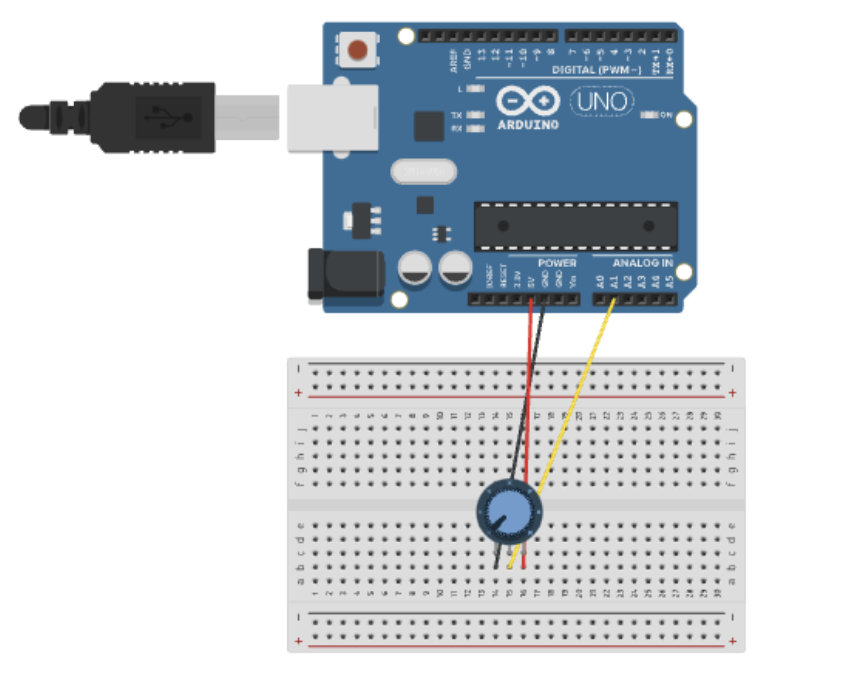
So, for the set-up, I just prepared the Arduino in a way that it functions with the code without being modified, since it already did everything needed for these two exercises. Although, in p5.js, I duplicated the example that we were provided on class to work with. Likewise, I did make changes since it would not replicate what was needed for exercise #1 and #2.

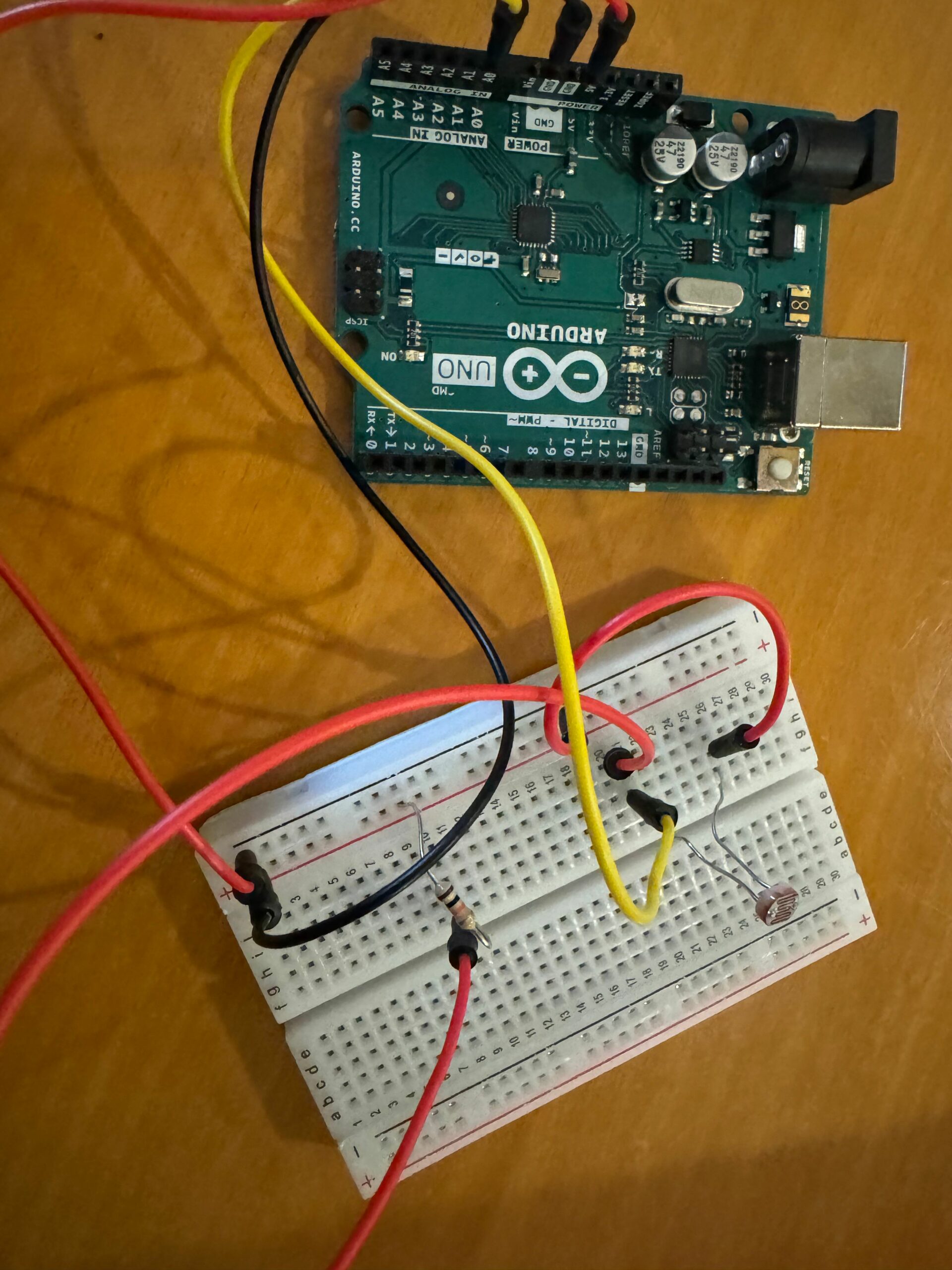
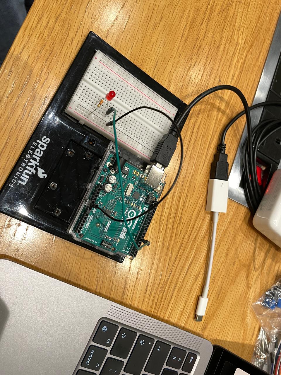
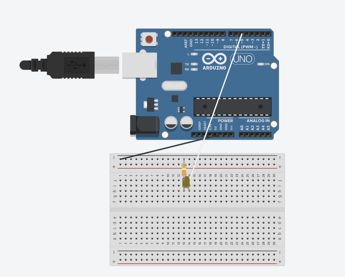
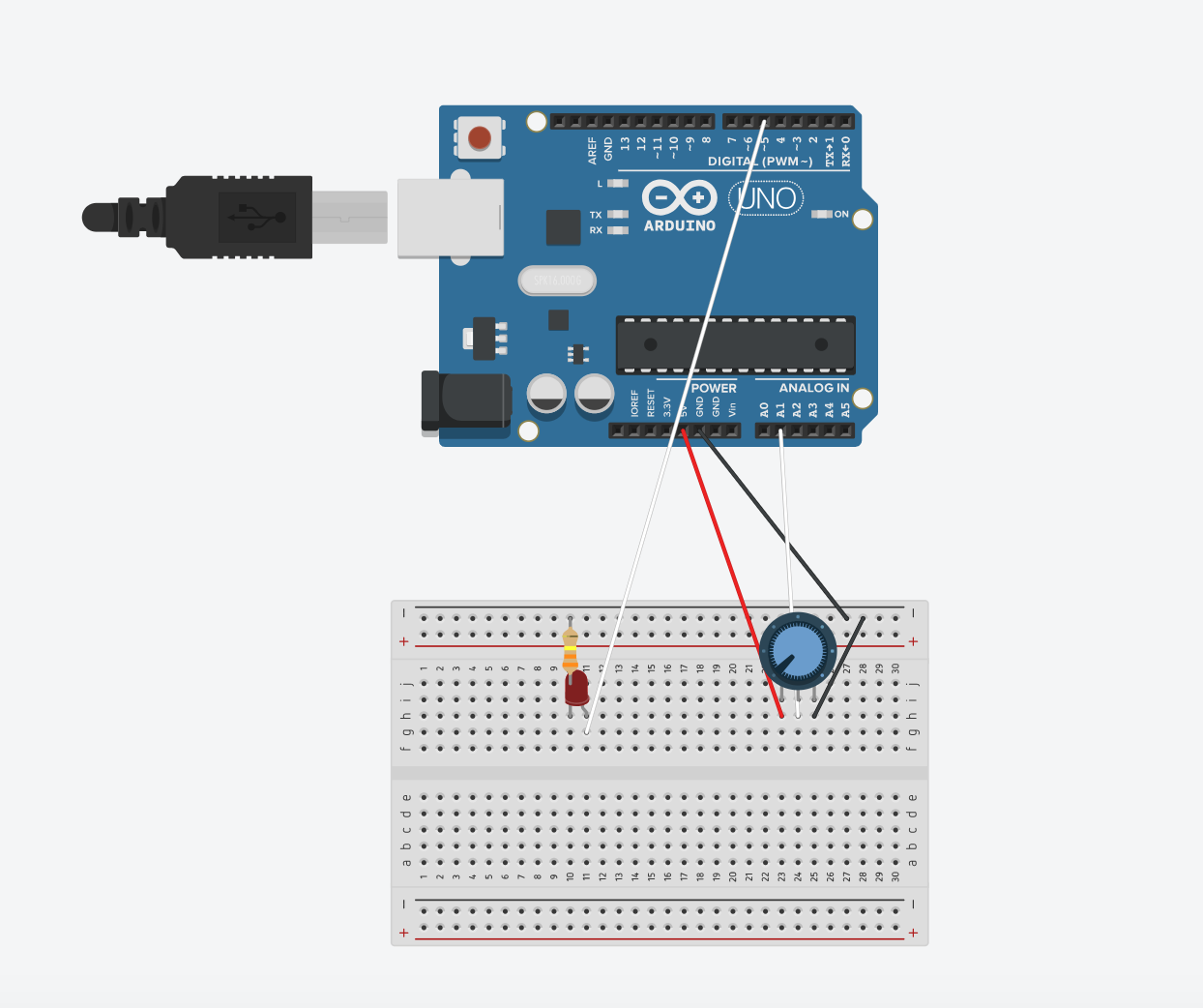
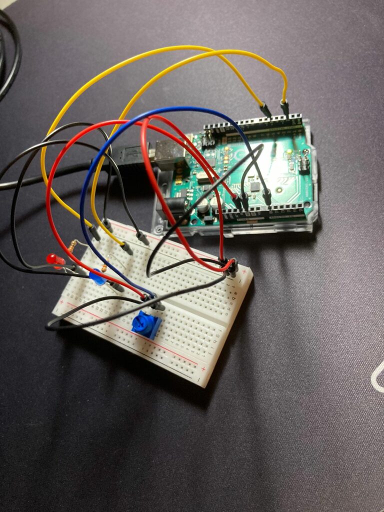
After setting up the Arduino, we have the following:

And with this code in p5.js that is modified so as every time the circle is clicked, the red LED gets turn on as well as having the possibility of moving it horizontally with a potentiometer via analog values:

let rVal = 0;
let alpha = 255;
let left = 0; // True (1) if mouse is being clicked on left side of screen
let right = 0; // True (1) if mouse is being clicked on right side of screen

function setup() {
  createCanvas(640, 480);
  textSize(18);
}

function draw() {
  // one value from Arduino controls the background's red color
  background(255)

  // the other value controls the text's transparency value
  fill(255, 0,0)

  if (!serialActive) {
    text("Press Space Bar to select Serial Port", 20, 30);
  } else {
    text("Connected", 20, 30);
    // Print the current values
    text('rVal = ' + str(rVal), 20, 50);
    text('alpha = ' + str(alpha), 20, 70);
  }

  // click on one side of the screen, one LED will light up
  // click on the other side, the other LED will light up
  if (mouseIsPressed) {
    if (mouseX > rVal-50 && mouseX < rVal+50 && mouseY > height/2-50 && mouseY < height/2+50) {
      right = 1;
    } 
  } else {
    right = 0;
  }
  ellipse(rVal, height/2, 50,50)
}

function keyPressed() {
  if (key == " ") {
    // important to have in order to start the serial connection!!
    setUpSerial();
  }
}

// This function will be called by the web-serial library
// with each new line of data. The serial library reads
// the data until the newline and then gives it to us through
// this callback function
function readSerial(data) {
  ////////////////////////////////////
  //READ FROM ARDUINO HERE
  ////////////////////////////////////

  if (data != null) {
    // make sure there is actually a message
    // split the message
    let fromArduino = split(trim(data), ",");
    // if the right length, then proceed
    if (fromArduino.length == 2) {
      // only store values here
      // do everything with those values in the main draw loop
      
      // We take the string we get from Arduino and explicitly
      // convert it to a number by using int()
      // e.g. "103" becomes 103
      rVal = int(fromArduino[0]);
      alpha = int(fromArduino[1]);
    }

    //////////////////////////////////
    //SEND TO ARDUINO HERE (handshake)
    //////////////////////////////////
    let sendToArduino = left + "," + right + "\n";
    writeSerial(sendToArduino);
  }
}

We have the following result observed in the video:

After completing these exercises, I started to feel more confident as to how I will work on my final project.

Exercise #3  –  Marwan AbdElhameed

This one is particular was challenging. Basically, the sensor data is sent to Arduino after mapping it to -1,1, then the Y position of the ball is sent to the Arduino and checked if it was >330. If it is, the LED at is switched to HIGH.

The code found in p5.js:

let velocity;
let gravity;
let position;
let acceleration;
let wind;
let drag = 0.99;
let mass = 50;

function setup() {
  createCanvas(640, 360);
  noFill();
  position = createVector(width/2, 0);
  velocity = createVector(0,0);
  acceleration = createVector(0,0);
  gravity = createVector(0, 0.5*mass);
  wind = createVector(0,0);
}

function draw() {
    if (!serialActive) {
    text("Press s to select Serial Port", 20, 30);
  } else {
    text("Connected", 20, 30);
    // Print the current values
    text('rVal = ' + str(rVal), 20, 50);
    text('alpha = ' + str(alpha), 20, 70);
  }
  
  background(255);
  applyForce(wind);
  applyForce(gravity);
  velocity.add(acceleration);
  velocity.mult(drag);
  position.add(velocity);
  acceleration.mult(0);
  ellipse(position.x,position.y,mass,mass);
  if (position.y > height-mass/2) {
      velocity.y *= -0.9;  // A little dampening when hitting the bottom
      position.y = height-mass/2;
    }
}

function applyForce(force){
  // Newton's 2nd law: F = M * A
  // or A = F / M
  let f = p5.Vector.div(force, mass);
  acceleration.add(f);
}

function keyPressed(){
  if (keyCode==LEFT_ARROW){
    wind.x=-1;
  }
  if (keyCode==RIGHT_ARROW){
    wind.x=1;
  }
  if (key==' '){
    mass=random(15,80);
    position.y=-mass;
    velocity.mult(0);
  }
   if (key == 's') {
    // important to have in order to start the serial connection!!
    setUpSerial();
  }
}

function readSerial(data) {
  ////////////////////////////////////
  //READ FROM ARDUINO HERE
  ////////////////////////////////////

  if (data != null) {
    // make sure there is actually a message
    // split the message
    let fromArduino = split(trim(data), ",");
    // if the right length, then proceed
    if (fromArduino.length == 1) {
      
      wind = int(fromArduino[0]);
    }

    //////////////////////////////////
    //SEND TO ARDUINO HERE (handshake)
    //////////////////////////////////
    let sendToArduino = position.y + "\n";
    writeSerial(sendToArduino);
  }
}

The code sent to the Arduino:

int leftLedPin = 2;

void setup() {
  // Start serial communication so we can send data
  // over the USB connection to our p5js sketch
  Serial.begin(9600);

  // We'll use the builtin LED as a status output.
  // We can't use the serial monitor since the serial connection is
  // used to communicate to p5js and only one application on the computer
  // can use a serial port at once.
  pinMode(LED_BUILTIN, OUTPUT);

  // Outputs on these pins
  pinMode(leftLedPin, OUTPUT);

  // Blink them so we can check the wiring
  digitalWrite(leftLedPin, HIGH);
  delay(200);
  digitalWrite(leftLedPin, LOW);


  // start the handshake
  while (Serial.available() <= 0) {
    digitalWrite(LED_BUILTIN, HIGH); // on/blink while waiting for serial data
    Serial.println("0,0"); // send a starting message
    delay(300);            // wait 1/3 second
    digitalWrite(LED_BUILTIN, LOW);
    delay(50);
  }
}

void loop() {
  // wait for data from p5 before doing something
  while (Serial.available()) {
    digitalWrite(LED_BUILTIN, HIGH); // led on while receiving data

    int left = Serial.parseInt();
    if(left>=330){
       digitalWrite(leftLedPin, HIGH);
}
  
    if (Serial.read() == '\n') {
      digitalWrite(leftLedPin, left);
      int sensor = analogRead(A0);
      sensor = map(sensor,0,1023,-1,1);
      Serial.println(sensor);

    }
  }
  digitalWrite(leftLedPin, LOW);
}

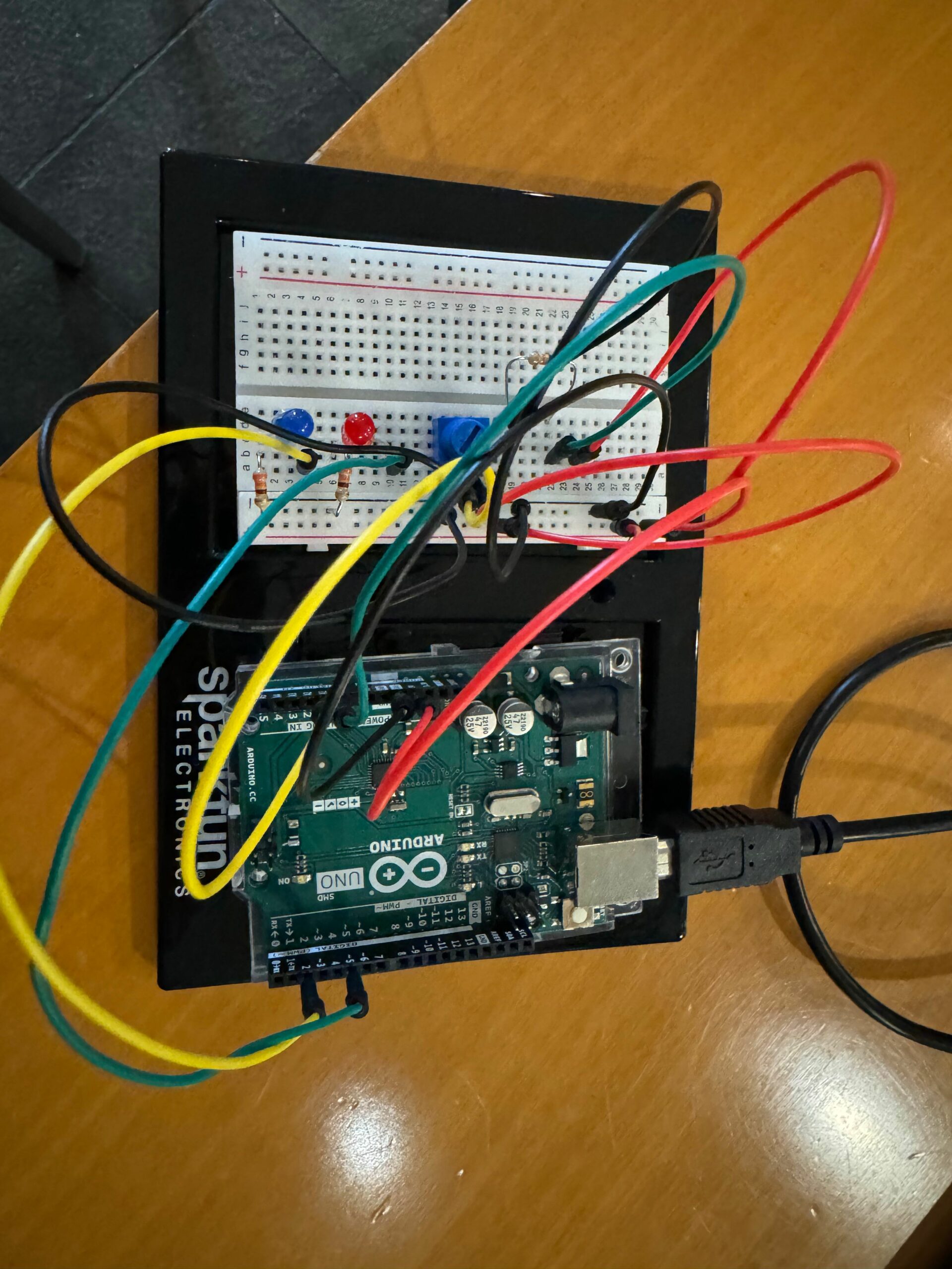
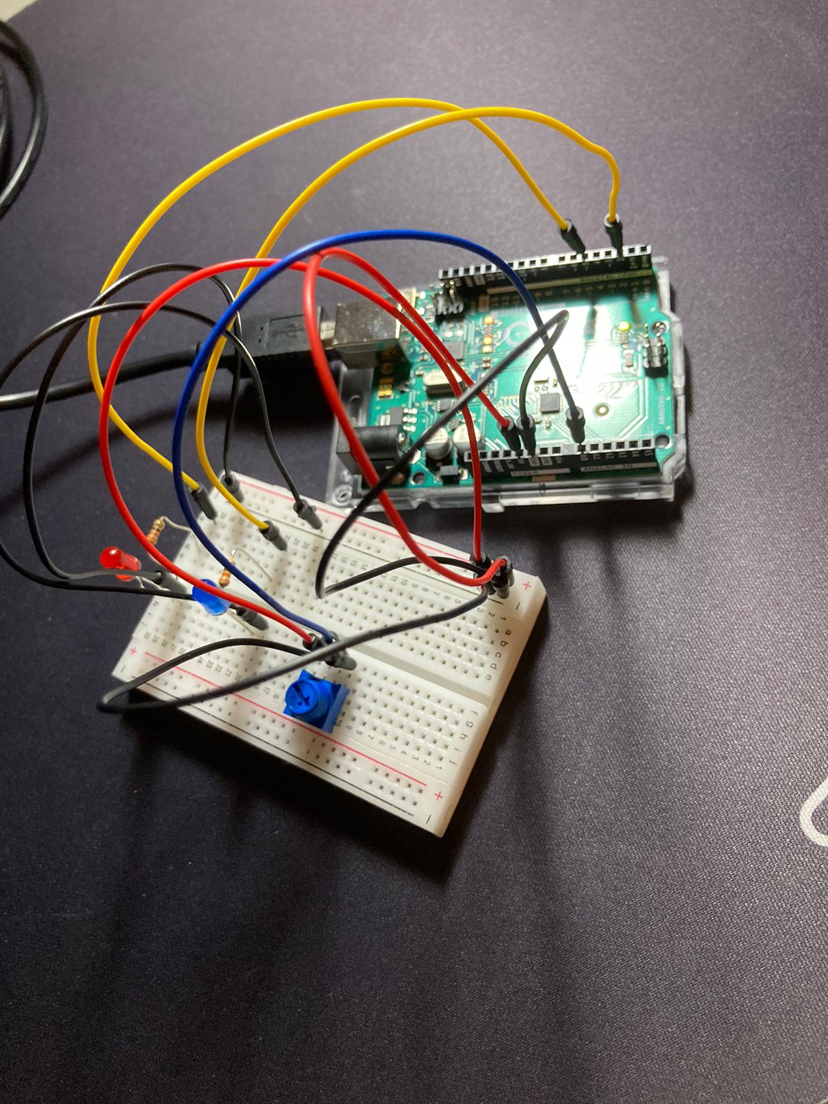
After sending the setting up the Arduino, sending the code and using the one that was written in p5.js, we have the following result:

Conclusion

Working on Arduino, at first sight, might appear scary and too technical. But with these exercises, both my teammate and I feel more comfortable with the Arduino world. As they say, the hardest step will always be the first, and the rest, should be left to curiousness.