Finalized Concept for the Project:
The final project involves developing a gyroscope-based controller using an Arduino that interfaces with p5.js to enhance the gaming experience in a space simulation game. This setup aims to provide a more intuitive and immersive way for players to control a spaceship using natural hand movements.
Design and Description of the Arduino Program
Hardware Setup:
Input: 3-axis gyroscope sensor integrated into an Arduino board. This sensor detects the controller’s orientation and motion.
Output: Serial signals sent to a computer running the p5.js application.
Functionality:
The Arduino program continuously reads data from the gyroscope sensor, including angular velocity and orientation relative to its starting position.
The program processes these data to determine the intended motion or command (e.g., turn left, accelerate).
These interpreted commands are then sent as serial data to the p5.js application, formatted as simple strings or numerical values.
Interaction with p5.js:
Sending: Commands such as “turn_left”, “turn_right”, “accelerate”, and “stop” based on gyroscope readings.
Receiving: The Arduino may receive feedback from the p5.js application for settings adjustments based on user preferences or gameplay state.
Design and Description of the p5.js Program
Software Setup:
Runs on a computer and serves as the interface between the Arduino controller and the space simulation game.
Functionality:
The p5.js application listens for serial communication from the Arduino, parsing the incoming data into actionable game commands. It translates these commands into manipulations of the game environment, such as rotating the spaceship or changing speed, ensuring real-time responsiveness to the player’s movements.
Interaction with Arduino:
Receiving: Commands like rotations and accelerations are received from the Arduino.
Sending: p5.js can send calibration data back to Arduino, error messages if commands are unrecognized, or game state information that might influence how sensor data is processed.
Conclusion
This project’s core is the integration of Arduino with a gyroscope sensor and the p5.js application. Arduino captures and interprets the controller’s physical movements, turning them into digital commands, while p5.js translates these into meaningful game interactions. This system is designed to elevate the player’s gaming experience, making it more engaging by simulating the piloting of a spaceship with realistic controls.
Make something that uses only one sensor on Arduino and makes the ellipse in p5 move on the horizontal axis, in the middle of the screen, and nothing on Arduino is controlled by p5
Make something that controls the LED brightness from p5
For these two exercises, we made it so that the potentiometer that is connected to the Arduino controls the LED on the breadboard and the ellipse in the p5 sketch in the middle of the screen, and also when the keyboard keys are pressed up or down it would change the brightness of that LED light.
P5.js Code:
let LEDbrightness = 0;

function setup()
{
  createCanvas(400, 400);
}


function textDisplay() //display text in the starting
{
  text("PRESS SPACE TO START SERIAL PORT", width/2 - 109, height/2 - 5);
}

function draw()
{

  background(255);

  if (serialActive) //if serial is active
  {
    text("CONNECTED", width/2 - 27, height/2 - 5);
    text("PRESS UP/DOWN ARROW KEYS TO CHANGE BRIGHTNESS!", width/2 -180, height/2 + 15);
  }
  else
  {
    textDisplay();
  }
}


function keyPressed() //built in function
{
  if (key == " ") //if space is pressed then
  {
    setUpSerial(); //setup the serial
  }
  else if (keyCode == DOWN_ARROW)
  {
    if (LEDbrightness != 0)
    {
      LEDbrightness = LEDbrightness - 20;
    }
  }
  else if (keyCode == UP_ARROW)
  {
    if (LEDbrightness != 250)
    {
      LEDbrightness = LEDbrightness + 20;
    }
  }

}

//callback function
function readSerial(data)
{
    let sendToArduino = LEDbrightness + "\n"; //add the next line to dimness counter
    writeSerial(sendToArduino); //write serial and send to arduino
}
Arduino Code:
const int LED_PIN = 5;
int brightness = 0;

void setup()
{
  Serial.begin(9600);

  pinMode(LED_PIN, OUTPUT);

  while (Serial.available() <= 0)
  {
    Serial.println("CONNECTION STARTED");
  }
}
void loop()
{

    while (Serial.available())
    {
      brightness = Serial.parseInt();
      Serial.println(brightness);

      if (Serial.read() == '\n')
      {
        analogWrite(LED_PIN, brightness);
      }
    }
}
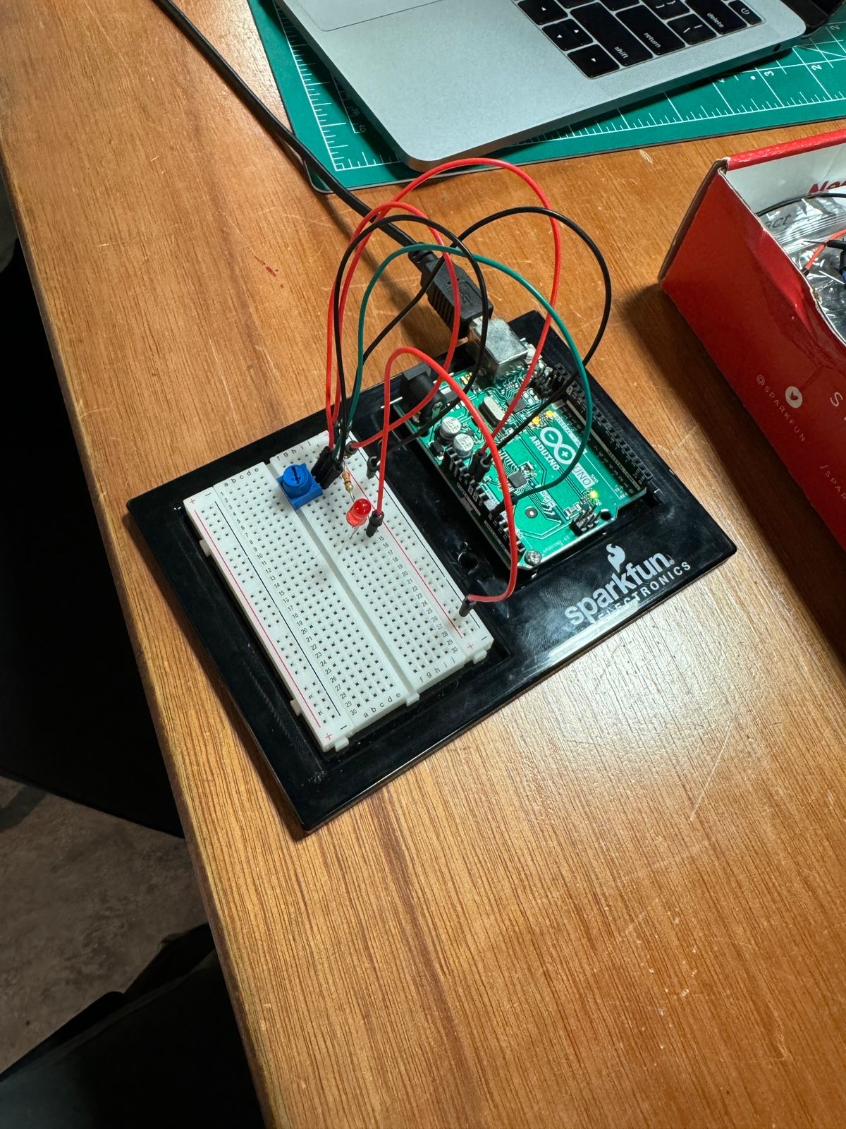
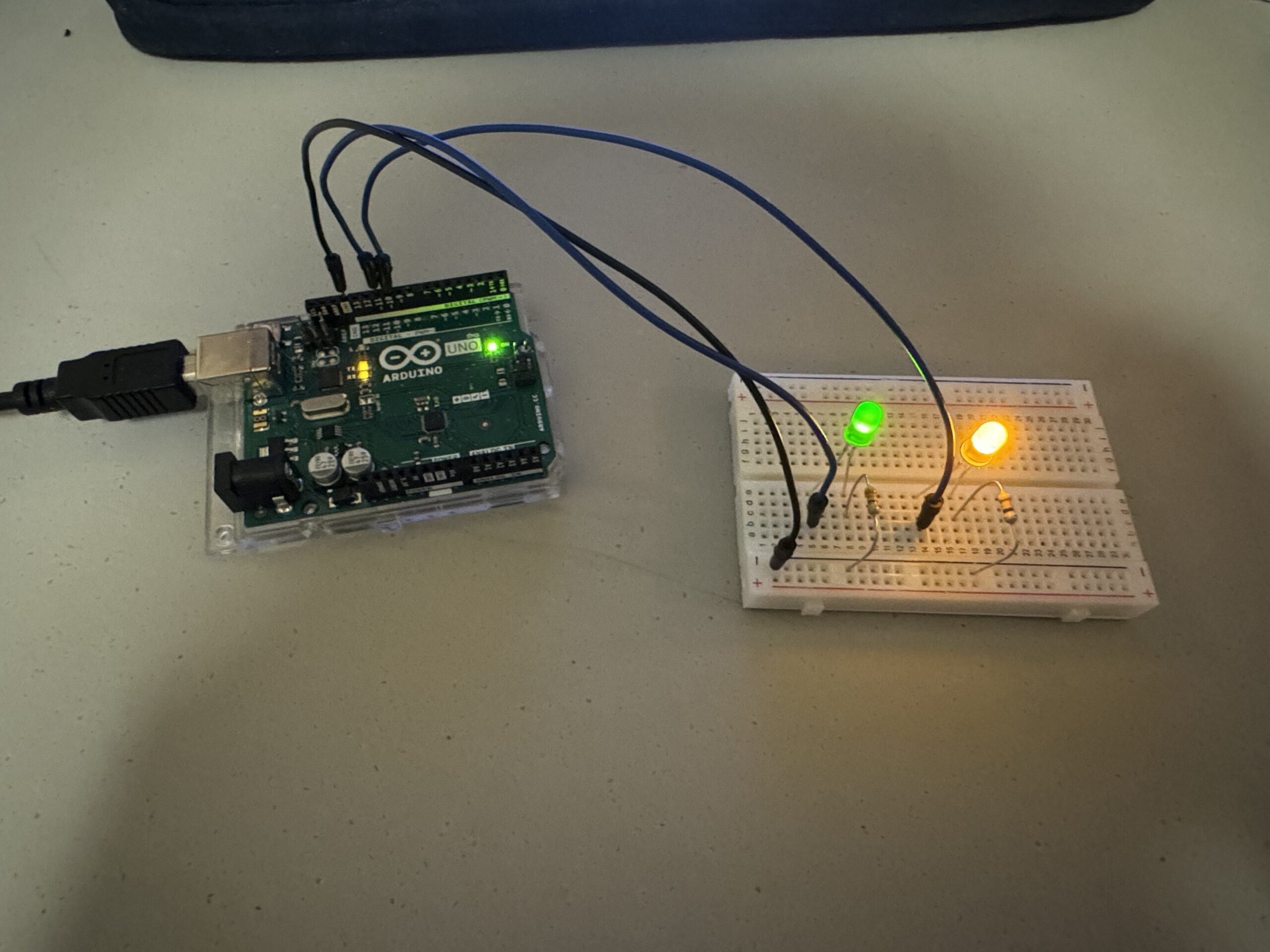
Video and Photos for Exercise 1:
For exercise 1, since we were just getting started, the main problem was understanding how serial communication works. We had some kind of idea when it was being presented to us, but until we started working, we didn’t really know. Other than that, there weren’t really any specific challenges. We didn’t need to use the trim() method, we had one value coming in from the Arduino, which was the potentiometer, and we had some troubles at first, but once we casted it as an integer value (it’s received as a string), then mapped it to the width and made the mapped value the x-position of the ellipse the project was done.
You’ll notice in the image that there’s an LED. The LED was there to test whether or not there was power being outputted from the potentiometer. We added it while we were debugging.
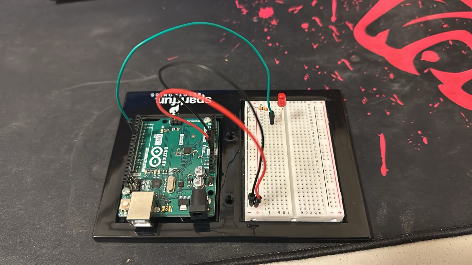
Video and Photos for Exercise 2:
Like the previous exercise there was only one value that was being communicated between the arduino and the p5js code so it was fairly simple. The hard part was just getting it such that tapping it reduced the brightness value by a specific amount and increasing it by a certain amount.
3. Take the gravity wind example and make it so every time the ball bounces one led lights up and then turns off, and you can control the wind from one analog sensor
For this exercise, the code creation uses p5, where physics principles like gravity and wind influence the ellipse’s motion. The sketch also communicates with the Arduino, which can control an LED based on the object’s motion, specifically if it bounces.
P5.js Code:
let dragForce = 0.99;
let mass = 20;
let ledState = 0;
let velocity;
let gravity;
let position;
let acceleration;
let wind;
let force;
let bounced = false;


function setup() {
  createCanvas(640, 480);
  textSize(18);
  position = createVector(width / 2, 0);
  velocity = createVector(0, 0);
  acceleration = createVector(0, 0);
  gravity = createVector(0, 0.3 * mass);
  wind = createVector(0, 0);
}

function draw() {
  background(0,40);
  // background(0);
  // background(255);

  if (!serialActive) {
    fill(255);
    text("Press Space Bar to select Serial Port", 20, 30);
  } else {

    noStroke();
    force = p5.Vector.div(wind, mass);
    acceleration.add(force);
    force = 0;
    force = p5.Vector.div(gravity, mass);
    acceleration.add(force);
    force = 0;
    velocity.add(acceleration);
    velocity.mult(dragForce);
    position.add(velocity);
    acceleration.mult(0);

    ellipse(position.x, position.y, mass, mass);
    if (position.y > (height - mass / 2)-30 ) {
      velocity.y *= -0.9;
      position.y = (height - mass / 2)-30;
      ledState= 1;

      if (!bounced) {
        fill(255, 0, 0); // Red when just bounced
        bounced = true; // Update bounce state
      } else {
        fill(255); // White otherwise
        bounced = false; // Reset bounce state
      }
    } else {
      ledState = 0;
    }


  }

  rect(0,height-30,width,30);

}

function keyPressed() {
  if (key == " ") {
    // important to have in order to start the serial connection!!
    setUpSerial();
  }
}

function readSerial(data) {
  if (data != null) {
    // make sure there is actually a message
    // split the message
    let fromArduino = split(trim(data), ",");
    // if the right length, then proceed
    if (fromArduino.length == 1) {
      let windCurrent = int(fromArduino[0]);
      wind.x = map(windCurrent, 0, 1023, -1, 1);
    }

    //////////////////////////////////
    //SEND TO ARDUINO HERE (handshake)
    //////////////////////////////////
    let sendToArduino = ledState + "\n";
    writeSerial(sendToArduino);
  }
}
Arduino code:
int ledPin = 5;
int potPin = A0;

void setup() {
  Serial.begin(9600);

  pinMode(LED_BUILTIN, OUTPUT);

  // Outputs on these pins
  pinMode(ledPin, OUTPUT);

  // start the handshake
  while (Serial.available() <= 0) {
    digitalWrite(LED_BUILTIN, HIGH); // on/blink while waiting for serial data
    Serial.println("0"); // send a starting message
    delay(300);            // wait 1/3 second
    digitalWrite(LED_BUILTIN, LOW);
    delay(50);
  }
}

void loop() {
  // wait for data from p5 before doing something
  while (Serial.available()) {
    digitalWrite(LED_BUILTIN, HIGH); // led on while receiving data

    int right = Serial.parseInt();
    if (Serial.read() == '\n') {
      digitalWrite(ledPin, right);
      int potValue = analogRead(potPin);
      delay(5);
      Serial.println(potValue);
    }
  }
}
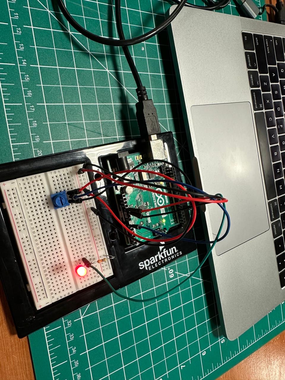
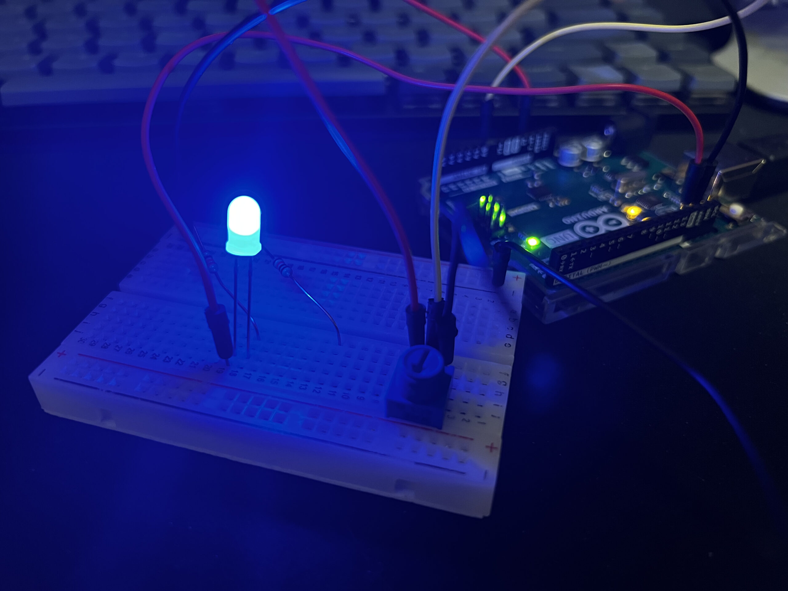
Video and Photos for Exercise 3:
Understandably, this was the hardest of the 3. We first manipulated the code given to us (which had the wind and ball code). We changed the wind global variable in much the same way as the first exercise: The potentiometer value was mapped to the wind variable. The hard part was the bouncing. There was a point during the exercise where we felt we had written everything correctly, and after going through the code together, we couldn’t see what was wrong. We made a variable called bounced and had it such that inside of the if statement, which would be called upon when the ball was supposed to bounce, the variable would be the opposite of what it was previously (if true then false, if its false then true). We then realized we were initializing the bounced variable inside of the draw function. We made it a global variable, and then it worked.
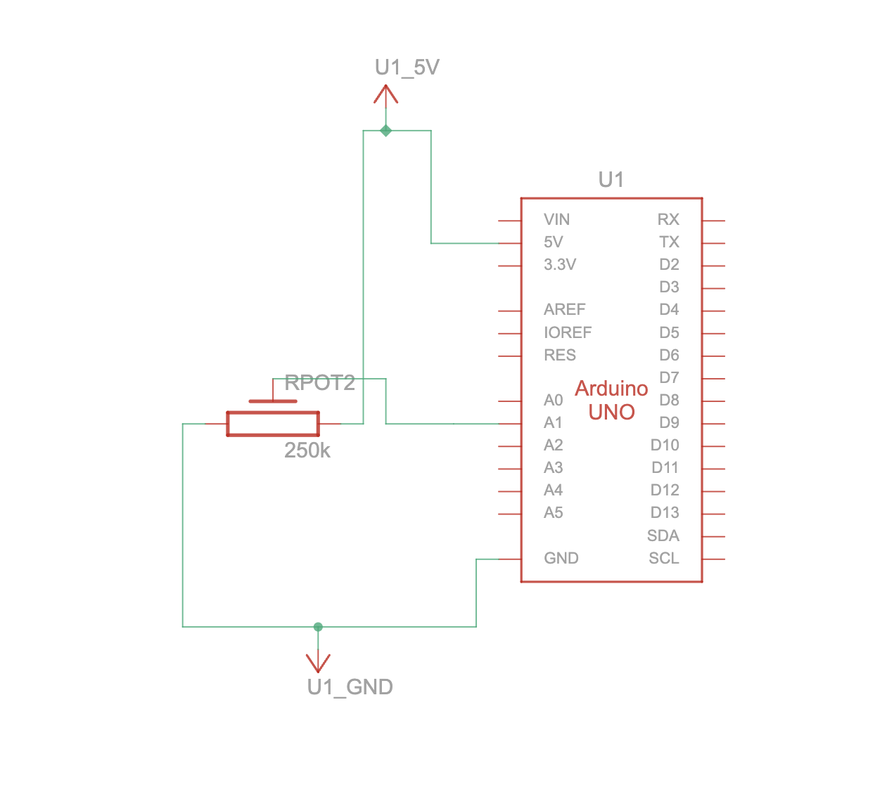
The Arduino continuously reads the electrical signal from a potentiometer. This signal represents the potentiometer’s position based on its rotation. The code then scales this raw sensor reading (ranging from 0 to 1023) to a new range of 0 to 400 using a function called map. This scaled value becomes the control signal for the circle’s movement on the web page.
The scaled sensor value (now within the 0-400 range) is sent from the Arduino to the p5js code running in the web browser. When data arrives to p5js, the code assigns it to a variable named circleX. This variable essentially controls the circle’s position on the screen. Finally, the code uses this value to dynamically adjust the horizontal position (X coordinate) of the circle drawn on the p5js canvas.
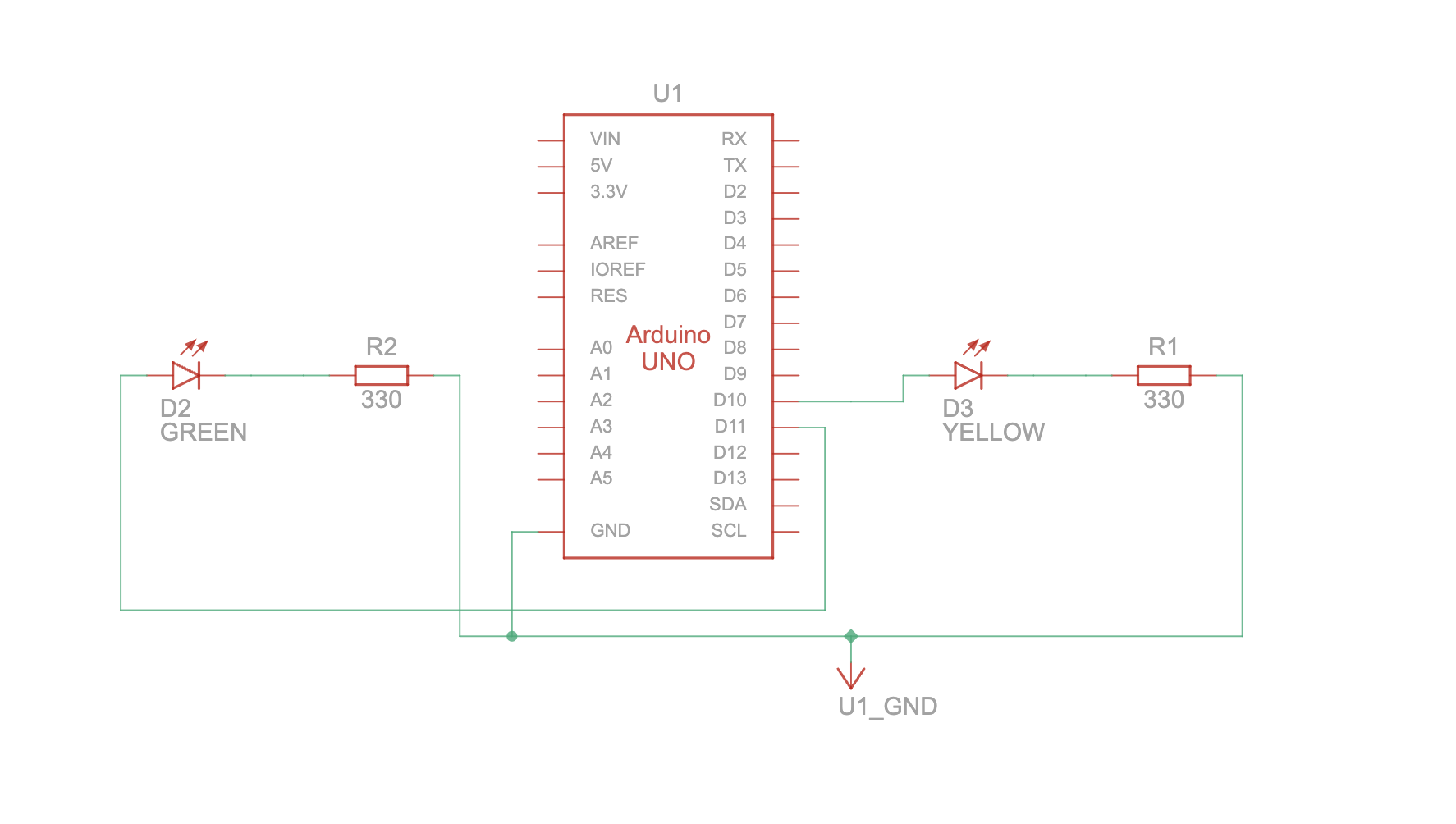
The p5js code continuously tracks the mouse cursor’s position on the canvas (represented by mouseX and mouseY variables). The p5js code directly assigns the mouseX value to the brightness 1 variable and the mouseY value to the brightness2 variable. These variables essentially store the desired brightness levels for the two LEDs. The readSerial function in p5js combines the brightness1 and brightness2 values with a comma (“,”) separator and adds a newline character (“\n”) to create a formatted message. This formatted message is then sent to the Arduino.
Once the data (representing the formatted message) are available, the code reads them using Serial.parseInt. This separates the combined brightness values stored in brightness1 and brightness2. The map function then scales both brightness values from the p5js range (0-400) to the appropriate range (0-255) for controlling the LEDs. The code includes error handling by checking for a newline character (\n) after reading the brightness values. This ensures complete data reception before setting the LED brightness. If no data is received, the Arduino prints an error message “No signal received” to the serial monitor. Finally, the Arduino sets the brightness of each LED (LED 1 on pin 10 and LED 2 on pin 11) based on the corresponding received values (brightness1 and brightness2).
The p5js code establishes the core mechanics for simulating a bouncing ball on the screen. It defines various physics concepts like: Gravity, Drag, Acceleration and Wind. The code continuously updates the ball’s position and velocity based on the applied forces and drag. When the ball hits the bottom of the canvas, its vertical velocity is reversed, simulating a bounce. At this point, a variable named ledOn is set to 1, indicating the LED should be turned on. If the serial connection is active, the code sends the ledOn value (0 or 1) as a string followed by a newline character (“\n”) to the Arduino using writeSerial.
The readSerial function gets called whenever new data arrives from the Arduino. Here, it parses the received data and assigns it to the windVale variable. This value updates the wind vector, influencing the ball’s horizontal movement in the simulation. The Arduino code continuously reads the analog value from a potentiometer connected to pin A0. It then maps this value (ranging from 0 to 1023) to a new range of -10 to 10 using the map function. This mapped value represents the wind force affecting the ball in the p5js simulation. The Arduino transmits this wind force value to the p5js code. The Arduino constantly checks for incoming data on the serial port. If data is available, it reads the first character and checks its value. If the character is ‘1’, the LED connected to pin 13 is turned on. If the character is ‘0’, the LED is turned off.
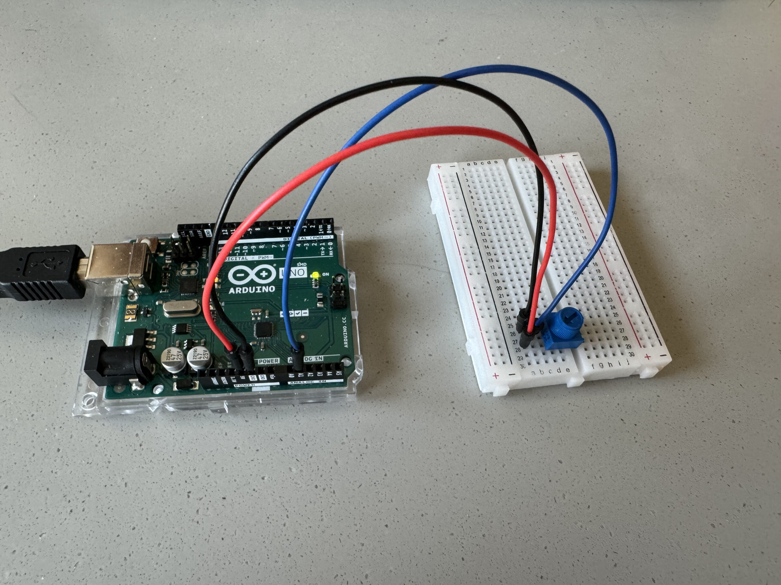
Hardware
Computer
Arduino Board
Potentiometer
LED
Connecting Wires
Bread board
Picture:
Video:
Schematics:
Code and other resources: Exercises 1 & 2: https://drive.google.com/drive/folders/1sVlmQsPKM8jgOwRl0b_gx8DIoMTCjYt0?usp=share_link
According to the other exercises, we tried multiple times with the code, and tried manipulating it to fit the requirments but we kept getting errors
After multiple trials we gave up and decided to dedicate all our time for our final project, however here is the code that was in progress with multiple errors:
the P5 code was the one giving us errors:
let serial;
let rVal = 0;
let alpha = 255;
let left = 0;
let right = 0;
let slider;

function setup() {
  createCanvas(640, 480);
  textSize(18);

  function setup() {
  console.log('Setting up...');

  serial = new p5.SerialPort();
  serial.on('data', readSerial);
  serial.on('open', onSerialOpen);
  serial.on('error', onSerialError);
  serial.open('COM3');  // Update this to your port
}


  slider = createSlider(0, 255, 127);
  slider.position(10, 10);
  slider.style('width', '380px');

  // Initialize the serial port
  serial = new p5.SerialPort();
  serial.open('COM3'); // change this to your Arduino port
  serial.on('data', readSerial); // function to call when new data arrives
  serial.on('open', onSerialOpen); // function to call when the serial port opens
  serial.on('error', onSerialError); // function to call on error
}

function draw() {
  background(map(rVal, 0, 1023, 0, 255), 255, 255);
  fill(255, 0, 255, map(alpha, 0, 1023, 0, 255));

  if (!serial.isOpen()) {
    text("Press Space Bar to select Serial Port", 20, 30);
  } else {
    text("Connected", 20, 30);
    text('rVal = ' + str(rVal), 20, 50);
    text('alpha = ' + str(alpha), 20, 70);

    if (slider.value() > 127) {
      left = 1;
      right = 0;
    } else {
      left = 0;
      right = 1;
    }

    let sendToArduino = left + "," + right + "\n";
    serial.write(sendToArduino);
  }
}

function keyPressed() {
  if (key === ' ') {
    serial.open('/dev/tty.usbmodem1411'); // open a serial port
  }
}

function readSerial() {
  let data = serial.readLine(); // read the incoming string
  trim(data); // trim off trailing whitespace
  if (!data) return;
  let fromArduino = split(data, ',');
  if (fromArduino.length >= 2) {
    rVal = int(fromArduino[0]);
    alpha = int(fromArduino[1]);
  }
}

function onSerialOpen() {
  console.log('Serial Port Opened');
}

function onSerialError(err) {
  console.log('Serial Port Error: ' + err);
}
For my final project, I am planning to develop an “Emotion-Based Room.” This innovative setup will utilize a webcam to capture the facial expressions of a user, employing machine learning models to recognize various emotions such as happiness, sadness, surprise, etc. I will use the ml5.js and face-api.js libraries to implement the emotion detection feature.
Based on the detected emotions, the room’s environment will dynamically adjust to enhance the user’s experience. Using p5.js, the system will control the playback of music to match the user’s current mood. Additionally, an Arduino system will regulate the room’s lighting to complement the emotional atmosphere.
The physical space will be modeled with essential furniture such as a sofa, bed, study table, and bathroom. I plan to incorporate custom-made pressure sensors on these furniture items to further personalize the room’s response. For example, if a person sits on the sofa, the system will interpret this as a mood for studying and adjust the lighting to a more focused setting. Similarly, lying on the bed will trigger the lights to turn off and the music to cease, facilitating a conducive environment for sleep.
This project aims to create a responsive living space that adapts not only to the expressed emotions of its occupant but also to their physical interactions within the room.
The reading on design and disability sparked a shift in my perspective, like adjusting a lens to see the world with newfound clarity. It highlighted the often-overlooked potential of aesthetics in assistive devices, challenging the notion that functionality must come at the expense of beauty. Glasses, as a prime example, seamlessly blend utility and style, demonstrating that assistive technology can be desirable and even fashionable. This revelation resonated deeply, aligning with my belief that good design enhances not just usability but also user experience and self-perception.
It’s like realizing that accessibility isn’t just about creating universally bland solutions, but rather celebrating diversity through targeted designs that cater to individual needs and preferences. Involving artists and fashion designers in this process can inject a sense of identity and personal expression into assistive devices, transforming them from purely functional tools into extensions of oneself. The shift in language from “patients” to “wearers” and “hearing aids” to “HearWear” further emphasizes this transformation, moving away from medicalized labels towards a focus on empowerment and individuality. This reading has ignited a passion within me to advocate for inclusive design that not only accommodates but also celebrates the unique needs and aspirations of all individuals.
1. Make something that uses only one sensor on Arduino and makes the ellipse in p5 move on the horizontal axis, in the middle of the screen, and nothing on Arduino is controlled by p5.
For this task, I have used a photoresistor as the sensor. The sensor reading is being sent to the P5.js sketch to move the ellipse on the horizontal axis and change the background color.
Arduino Code
const int analogIn = A1;
void setup() {
  Serial.begin(9600);
}
void loop() {
    int analogValue = analogRead(analogIn);
    Serial.println(analogValue);
}
2. Make something that controls the LED brightness from p5
For this task, I have made a p5.js sketch that makes the canvas a switch. If you click on the left of the canvas, the LED brightness decreases and the color of the canvas gets darker. Conversely, if you click on the right of the canvas, the brightness increases and the canvas becomes lighter.
Arduino Code
int LED = 11;

void setup() {
  pinMode(LED, OUTPUT);
  Serial.begin(9600);
  while (Serial.available() <= 0) {
    Serial.println("Initializing Connection");
    delay(200);
  }
}

void loop() {
  while (Serial.available()) {

    int brightness = Serial.parseInt();
    if (Serial.read() == '\n') {
      analogWrite(LED, brightness);
      Serial.println("ON");
    }
  }
}
3. Take the gravity wind example and make it so every time the ball bounces one LED lights up and then turns off, and you can control the wind from one analog sensor
In this exercise, I established bi-directional data exchange. Firstly, when the ball hits the ground in the p5.js sketch, a signal is sent to the Arduino. This signal is triggered by checking if the bottom portion of the ellipse touches the lower boundary of the canvas. Upon receiving this signal, the Arduino program toggles the LED accordingly. Conversely, the Arduino sends the photoresistor value to p5.js. This value is mapped to the range of wind strength (wind.x).
Arduino Code
const int analogIn = A0;
const int LED = 12;
void setup() {
  Serial.begin(9600);
  pinMode(LED_BUILTIN, OUTPUT);
  pinMode(LED, OUTPUT);
  pinMode(analogIn, INPUT);
  while (Serial.available() <= 0) {
    digitalWrite(LED_BUILTIN, HIGH);
    Serial.println("0,0");
    delay(200);
    digitalWrite(LED_BUILTIN, LOW);
    delay(50);
  }
}
void loop() {
  while (Serial.available()) {
    digitalWrite(LED_BUILTIN, HIGH);
    digitalWrite(LED, LOW);
    int position = Serial.parseInt();

    if (Serial.read() == '\n') {
      int sensorValue = analogRead(analogIn);
      Serial.println(sensorValue);
    }
    if (position == 0) {
      digitalWrite(LED, HIGH);
    } else {
      digitalWrite(LED, LOW);
    }
  }
  digitalWrite(LED_BUILTIN, LOW);
}
This week’s reading, “Design meets Disability,” offered a new perspective on combining design with accessibility, particularly emphasizing the role of aesthetics in functional products for individuals with disabilities. It made me reflect on products like glasses, which are not typically seen as disability aids. Could their widespread acceptance and fashionability be the key to changing how we perceive all assistive devices? Glasses challenge the old notion that assistive devices must sacrifice aesthetics for functionality, illustrating that you can have both. This concept resonates with me and aligns with previous readings (The Design of Everyday Things: The Psychopathology of Everyday Things; and A Brief Rant on the Future of Interaction Design.) that suggested attractive products enhance user experience and influence consumer choices more than technical features. For example, the iPhone, while not always the most technologically advanced, remains popular for its intuitive and appealing design. This revelation led me to reconsider how products that are both functional and good-looking could redefine societal standards and expectations around disability.
Further exploration into the role of artists and fashion designers in normalizing and destigmatizing disability aids underscores the transformative power of inclusive design. Why haven’t we involved more creative professionals in these discussions before? The article highlights the importance of a collaborative approach in design processes, integrating insights from various disciplines to achieve a balance between functionality and aesthetics. This approach not only widens the scope of what can be developed but also enhances the user experience for people with disabilities, offering them the luxury of choice and the pleasure of recognition—privileges often reserved for the able-bodied. This shifted my previous belief from advocating for universal design to recognizing the value of targeted, specialized designs that meet specific needs without adding unnecessary complexity. The discussion about linguistic changes—from “patients” to “wearers” and from “hearing aids” to “HearWear”—raised interesting questions about how language shapes our perceptions of technology and disability. This reading challenged me to rethink how inclusivity can be woven into the fabric of design, aiming not just to add it as an afterthought but to integrate it as a foundational principle that enhances the dignity and quality of life for all users.