Week 9 – Saeed Lootah

Before this assignment I spent a lot of time trying to brainstorm different ideas, I wasn’t really sure what to do until the last minute to be honest. Some of my ideas were if you say a specific word the switch triggers, or if you’re nodding off or maybe just a sound trigger, but none of those ideas seemed very original or interesting. Thankfully I ended up coming up with an idea I feel is far more unique.

When thinking about different limbs (other than my hands) and which I could move to cause the switch to turn on I eventually landed on my ear. Unlike most people I have the ability to slightly move my left ear. Not enough to be very noticeable but enough to have two contacts connect or disconnect.

The plan was to connect one wire to my glasses and one wire to the side of my head. I chose to do this because I noticed that when I do move my ear it also moves my glasses. Therefore, the switch would be turned on when I don’t move my ear as the glasses would be in its normal position, and the switch would be turned off once I move my ear.

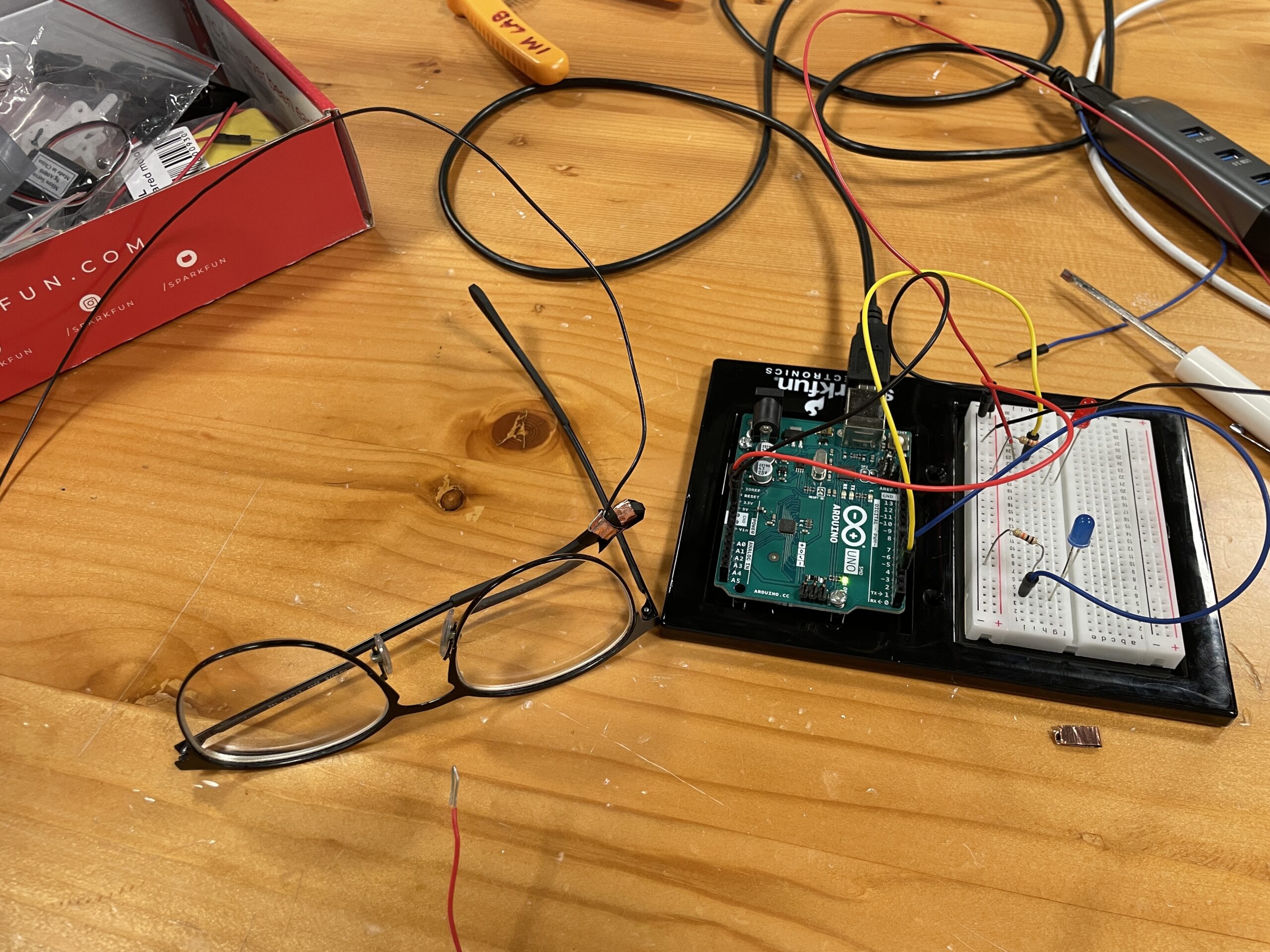
Above is the finished product when it is not attached to me. The red wire on the bottom left is what I attach to my head with electrical tape and it is supposed to touch the copper contact that you can see on my glasses. You may also notice that on the breadboard there are two LEDs, one red, one blue. The red LED turns on when current is flowing between the contacts. Then the blue LED is connected to the Arduino. When the current is flowing a signal is sent to the Arduino, then the output is sent to the blue LED. I made it such that the blue LED flickers when current isn’t flowing, i.e. when I move my ear.

Making this was very tedious especially getting the wire on my head to stick and also because sometimes I had to take my glasses off while working on the project. Fortunately while writing this my glasses are on but I didn’t attach the red wire. Unfortunately, when I do attach the red wire it is slightly uncomfortable so I’ve decided to keep it disconnected until the last moment. There are also other problems with my design: The wires easily move around, I rely heavily on electrical tape to keep everything in place, and to make sure everything works I have to adjust my glasses as well since if they move then the switch no longer works, also the wires are messy. Since this is only a prototype problems are expected. Regardless I’m surprised at how well it works, for people who don’t realize I’m moving my ear it looks like I’m using my mind alone to control the light.

Thank you Aadhar the lab assistant for helping me with getting wires of the right length and finding electrical tape. And, thank you ChatGPT for writing the flicker code.


Code:


// PINS //
const int powerPin = 2;
const int outputPin = 3;
// ---------- //

// GLOBAL VAR //
int val = 0;
int outputVal = 0;
bool flicker = false;
// unsigned long time;
unsigned long previousMillis = 0;   // ChatGPT
const long interval = 200;
// ---------- //

void setup() {
  // note to self, returns either HIGH or LOW
  pinMode(powerPin, INPUT);
  pinMode(outputPin, OUTPUT);

  
  // Serial.begin(1000); // Begins serial communication with my computer

}

void loop() {
  // DIGITAL READ //
  val = digitalRead(powerPin);
  digitalWrite(outputPin, outputVal);
  // // ---------- //

  // time = millis();
  unsigned long currentMillis = millis(); // get the current time

  // Test
  // if(val == LOW) {
  //   outputVal = LOW;
  // } else {
  //   outputVal = HIGH;
  // }

// turn on later 
  if (currentMillis - previousMillis >= interval) {
      // save the last time you blinked the LED
      previousMillis = currentMillis;
      flicker = !flicker;
  }

  if(flicker && val == HIGH) {
    outputVal = HIGH;
  } else {
    outputVal = LOW;
  }

  // Serial.println();
}


Week 9 – Personal Distance Machine

For my first Arduino-based assignment I wanted to incorporate the use of an ultrasonic sensor to generate an interaction for the user based on their presence alone. My initial idea was to have the output in the form of a message displayed on an LCD screen – I even wired up the circuit for this idea as shown below. However I was unable to figure out how to link information from the sensor to the LCD screen and decided to try a new approach.

In an attempt to simplify things for myself while maintaining the idea of detecting someone’s/something’s presence, I decided to create a ‘personal distance machine’ which tells users when something is too close for comfort. To do this I replaced the LCD screen with a buzzer and an RGB light which changes incrementally from green to yellow to red depending on the distance detected by the sensor. Below is an excerpt from the code as well as an example video.

void loop() {
  distance = getDistance();   //variable to store the distance measured by the sensor

  Serial.print(distance);     //print the distance that was measured
  Serial.println(" in");      //print units after the distance

  if (distance <= 20) {                       //if the object is close

    //make the RGB LED red
    analogWrite(redPin, 255);
    analogWrite(greenPin, 0);
    analogWrite(bluePin, 0);
     tone(buzzerPin, 272);  


  } else if (20 < distance && distance < 40) { //if the object is a medium distance

    //make the RGB LED yellow
    analogWrite(redPin, 255);
    analogWrite(greenPin, 50);
    analogWrite(bluePin, 0);

  } else {                                    //if the object is far away

    //make the RGB LED green
    analogWrite(redPin, 0);
        analogWrite(greenPin, 255);
    analogWrite(bluePin, 0);
        noTone(buzzerPin);   
  }

https://youtube.com/shorts/5y1aWPqcZVg?feature=share

Week 9: Unusual Switch (Sleep-Snitcher 3000)

The Switch itself

Before going into the background, let’s look at the switch itself:

Concept

A switch to be controlled by a body part other than the hand is not completely out of the realm of imagination, but it is quite difficult to imagine, especially for a circuit based on an Arduino. When I went to collect the copper strip from the IM lab, I got the idea of taping it to my forehead. And that’s how Sleep-Snitcher 3000 was born.

Conceptually, it is a tongue-in-cheek detector of whether a student is sleeping in class. When a student’s forehead is on the table, the LED lights up. This may also be the right place to add a disclaimer that the maker of this project does not advocate the use of this in schools or other educational institutions. It is meant to only be a fun and slightly satirical project.

Design

Circuit Diagram of the circuit, which goes from 5V pin on Arduino, to a 330ohm resistor, to the components acting as the switch to the led and finally to the GND pin. 
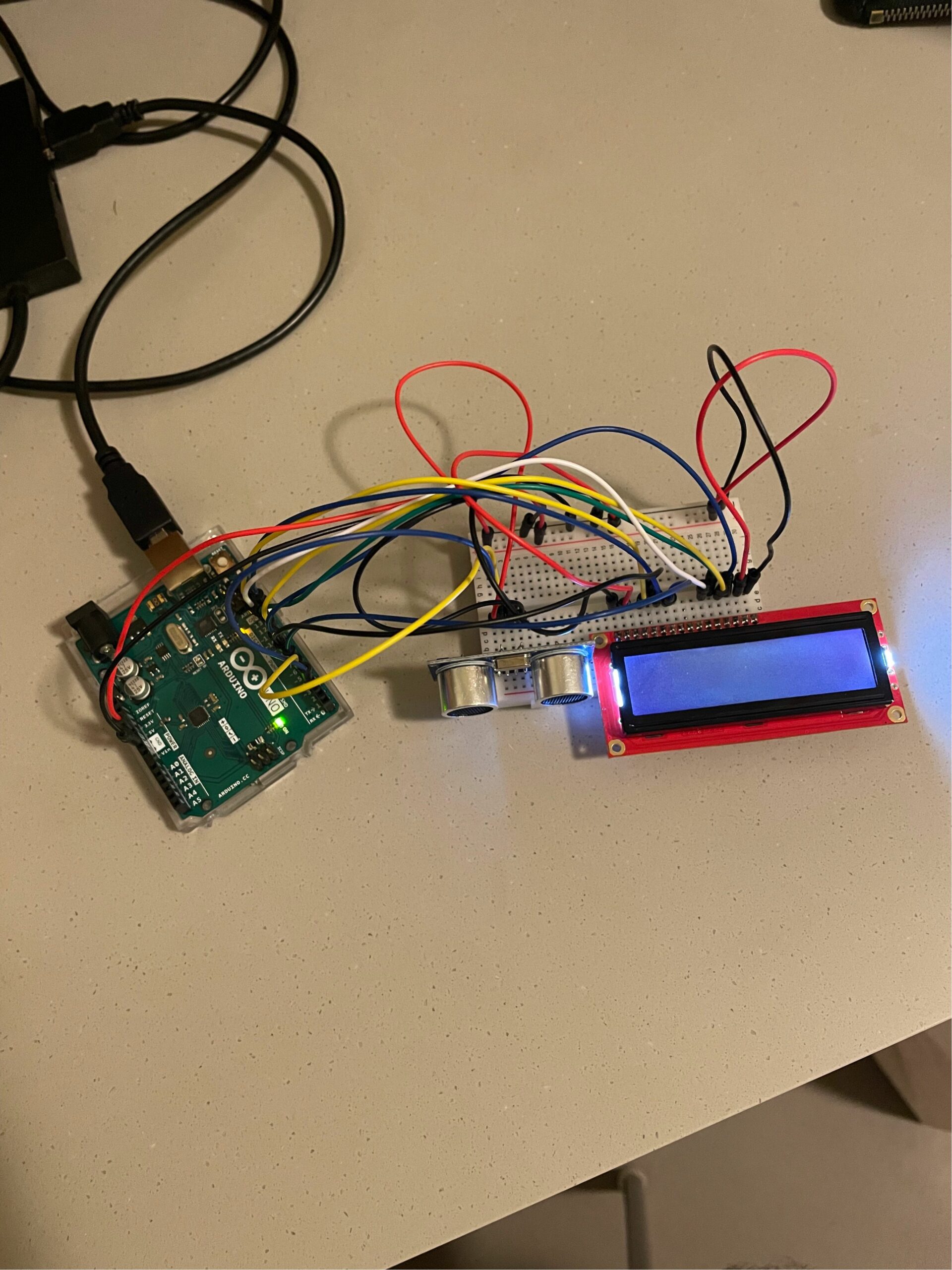
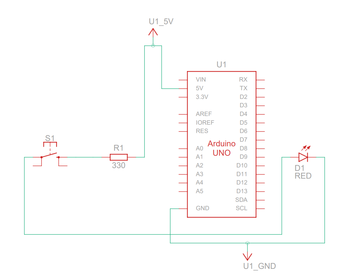
Figure 1: Circuit Diagram

The circuit is pretty simple. After this is all that the assignment actually requires. The above is a slightly confusing diagram from Tinkercad that shows the circuit design.

The 5V DC power output pin is used to keep the resistor and one terminal of what is technically a push-button switch live. When my forehead is on the table, it connects the two terminals of the “push-button switch” and thus lights up the LED, whose anode is connected to the the switch and cathode to GND (ground).

Materials

  1. Arduino Uno Rev3 SMD x1
  2. Jumper wires x5
  3. 330Ω carbon resistor x1
  4. Breadboard with 400 contacts x1
  5. Basic Red 620nm LED x1
  6. Aluminum Foil x1 A4 sheet (courtesy of Indian by Nature!)
  7. Copper Tape x10 inches
  8. Paper Bag x1

Implementation

At first, I was planning to connect one terminal to an aluminum foil sheet on the table and the other to my forehead. This came with a major problem: the wires were just too short. Besides, a hypothetical customer of this product wouldn’t want to connect and disconnect themselves from a circuit repeatedly. Then I remembered that in push-button switches, the button itself is usually not a terminal of the switch but acts as a wire bridging the two terminals. So, I came up with the following split-terminal design using aluminum sheets.

Two aluminum sheets connected to wires linked to a breadboard.
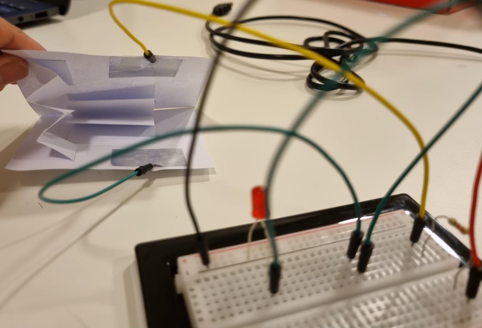
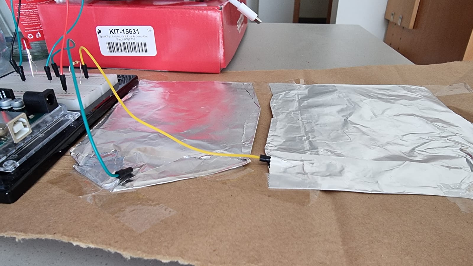
Figure 2: Switch terminals (the green terminal is +ve and the yellow terminal is -ve)

The copper strip simply goes across the forehead and that’s pretty much it.

And finally, the breadboard components were obtained from the Sparkfun kit we were provided, and the Arduino was connected to a laptop for power supply.

Reflections

This turned out to be more fun and simpler than I thought it would be. This was my first experience with Arduino outside of our class, but it felt nice to directly apply the concepts that were drilled into us by both high school physics and FOS. Also, the switch was surprisingly consistent, as I had expected that the circuit would be interrupted by a layer of insulating aluminum oxide. All in all, it was a fun project, with a fun concept.

Use of Generative AI

Generative AI (OpenAI ChatGPT 3.5) was used to name the project (the original name was A Student’s Nightmare) and to generate the disclaimer at the end of the video.

Creative Switch: Trash Can

For my first Arduino project, I was struggling to find ideas that didn’t involve my hands. I looked around my room, trying to utilize what I already have, and searched for objects that require the use of the body (not hands) to function. Which is when I saw my trash can! The idea was simple, create a circuit that closes when I press down on the trash can to open, and the circuit opens when I remove my foot. I used two foil pieces one stuck to the ground and one to the bottom of the trash can lever, allowing them to intersect and close the circuit when I press down with my foot. 

Additionally, the code was pretty straightforward, exactly what we’ve been doing in class:

const int ledPin = 2;
const int foilPin = 3;

void setup() {
  pinMode(ledPin, OUTPUT);
  pinMode(foilPin, INPUT);
  Serial.begin(9600);
}
void loop() {
  int buttonState = digitalRead(foilPin);
  Serial.println(buttonState); 
  digitalWrite(ledPin, buttonState); 
}

Overall, the code functions by reading the state of the aluminum foil switch and uses that info to control the state of the LED (high/low). When the switch is closed, the LED turns on, and when the switch is open, the LED turns off.

However, I faced several issues during my project:

Error messages from IDE kep showing up, after multiple attempts to troubleshoot (going back and forth between Arduino and IDE) I decided to restart my laptop and Arduino board which ended up solving the issue.

My second issue was that the Led light stays on regardless of the foils touching or not, it’s like the circuit was complete or was not relying on the foils. However, when the foils do touch the led light gets brighter which meant there was an intervention from the foils but not exactly what I’m looking for. I tried to find ways to trouble shoot this but ended up giving up after going back and forth with the code and the board. 

Here’s a Demo:IMG_6092 2

Week 9: Chin Up (Unusual switch)

For this assignment, I wanted to create an unusual switch that didn’t use my arms or legs. I thought about different body parts and the next best part for me was my chin. I was then thinking of different conductors to complete the circuit and while I was eating at Indian By Nature, I realized I could use the aluminum foil.

The rest of the circuit was straightforward to create. The switch is created by having two pieces of paper that pop up from each other, to which I stuck some aluminum foil on either side, under which each jumper wire is inserted.

Video:


Overall, I am happy with the outcome. It’s nice to see the LED light up after being uncertain if it was going to work or not. Whenever I was struggling in between to get things to stay in place and work, all I had to say to myself was chin up!:)

I would like to further improve my project by adding different “pedals” for different body parts and connect them to separate LEDs.

Week 10 – Sara Al Mehairi

Concept

Credit: iStock

For this assignment, my goal was to create a miniature car sensor system using Arduino. The system uses ultrasonic sensors to detect objects/vehicles and provide feedback to the user using RGB LED, similar to the sensors used in modern cars for reversing or parking assistance. Components used include: Arduino Board, Breadboard, Ultrasonic Sensors, RGB LED, 330Ω Resistors, and Jumper Wires.

Overview

Ultrasonic sensors for linear position and distance measuring
Credit: Texas Instruments

if (distance <= 10) {
    //red
    analogWrite(redPin, 255);
    analogWrite(greenPin, 0);
    analogWrite(bluePin, 0);
  } else if (10 < distance && distance < 20) {
    //orange
    analogWrite(redPin, 255);
    analogWrite(greenPin, 50);
    analogWrite(bluePin, 0);
  } else {
    //green
    analogWrite(redPin, 0);
    analogWrite(greenPin, 255);
    analogWrite(bluePin, 0);
  }
  • Distance Measurement: With some googling, I learned that ultrasonic sensors emit high-frequency sound waves and measure the time it takes for the waves to bounce back after hitting an object. Based on this time measurement, the system calculates the distance to the obstacle.
  • Visual Feedback: The RGB LED is used to provide visual feedback to the user based on the distance readings from the sensors. The LED changes color to indicate the proximity.
  • Consistency: the Arduino continuously monitors the distance readings from the sensors & updates the LED color accordingly. In reality or with the vision I had in mind, this real-time feedback would help the driver to move the vehicle carefully, especially in tight spaces.

IMPLEMENTATION

As the vehicle/object moves, the ultrasonic sensors detect obstacles in the path and passes on distance measurements to the Arduino. The Arduino then processes the distance readings and controls the RGB LED to provide real-time visual feedback to the driver. This is possible thanks to the loop that continuously retrieves distance measurements & adjusts the LED colors accordingly. I also came across echoTime which represents the duration for which the ultrasonic sensor receives an echo signal after emitting a sound wave, pretty cool!
– Red: Stop the vehicle immediately.
– Orange: Proceed with caution, slowing down if necessary.
– Green: Continue driving as the path is clear.

Conclusion

Tiny but mighty, it was quite enjoyable to create this miniature system. Although I may have accidentally followed the description of next week’s assignment and realized it a few minutes ago, I learned a lot. As a driver, I understand the importance sensors play in parallel parking and avoiding hitting a curb. Therefore, I wanted to contribute to improving this aspect in terms of accuracy. After encountering some obstacles, I resorted to Core Electronics on YouTube as a guide for this assignment. Overall, I had hoped to attach the sensors to the front or rear bumper of an actual vehicle and test the accuracy, but step by step, I’ll hopefully create something greater!

Week 9 Creative Switch – Khalifa Alshamsi

Concept:

In an endeavor to merge the timeless charm of LEGO with the dynamic glow of LED lighting, I took on a project that tested my creativity and also my persistence. The challenge was clear: integrate an LED system within a LEGO car in a functional and aesthetically pleasing manner. After numerous attempts and exploring various configurations, I found the perfect harmony by positioning the LED as the car’s internal dome light. This strategic placement allowed me to achieve an interactive feature where the light automatically turns on as the door closes and dims when the door is left open.

Code:

int ledPin = 9;           // LED connected to digital pin 9
int doorSensorPin = 2;    // Sensor (wires touching) connected to pin 2
int doorState = 0;        // Variable for reading the sensor status

void setup() {
  pinMode(ledPin, OUTPUT);      // Sets the digital pin as output
  pinMode(doorSensorPin, INPUT); // Sets the digital pin as input
  digitalWrite(doorSensorPin, LOW); // Enables pull-down resistor
}

void loop(){
  doorState = digitalRead(doorSensorPin); // Reads the state of the sensor value
  if (doorState == HIGH) {
     digitalWrite(ledPin, LOW);   // Turns LED off when the door is closed (wires touching)
  } else {
     digitalWrite(ledPin, HIGH);  // Turns LED on when the door is open (wires not touching)
  }
}

Video of Project:

Reflection and ideas for future work or improvements:

As I look back on this complicated project for me, I recognize the journey was as enlightening as it was challenging. One significant area for improvement that stands out is the need for a more refined wiring management system. Despite the project’s success, the sight of exposed wires and adhesive tape detracts from the overall aesthetic appeal. In future iterations, prioritizing a sleeker integration of the electronics will hopefully enhance the design.

Furthermore, this project served as a profound learning curve. Despite consuming countless videos and undergoing a trial-and-error process that saw me revising the wiring and code more times than I can count, I confess there remains a haze around my understanding of the underlying electronics principles. This realization, far from discouraging me, has sparked a curiosity to delve deeper into the fundamentals of electronics and programming.

Looking Ahead:

This project has laid the groundwork for further exploration into the fusion of technology with traditional toys. Ideas for future projects include incorporating more interactive elements, such as sound effects synchronized with the door’s motion or ambient light sensors to activate the headlights in dim conditions, transforming the LEGO car into an even more immersive and interactive experience, maybe even fully coding a 3D printed one to drive using the Arduino but again I still don’t know the full stretch of an Arduino board.

In essence, this journey has not only expanded my technical skills but also opened up a scenery of possibilities for exploring.

Week 9 | Blinking Light

I was quite busy this week with assignments from other classes that took more time than I had anticipated. Alas, I was quite idea-blocked on what to do for this unusual switch assignment.

Originally, I wanted to see if I could use sound sensors to turn on / off LEDs. However, the IM Lab does not have a sound sensor as of yet. So, I opted for photoresistors.

Exploring the examples provided by Arduino IDE, I found out the fading feature of LED. While it is not an inbuilt feature, by adding delays per update to the LED, we can simulate fading lights.

So, I figured what if I could combine both photoresistors’ outputs with fading light? Well, this is what I made:

I wanted to have some kind of if statements that go beyond what I have here. In my head, I wanted it so that each certain range of photoresistor would give different signals to the light: blinking, full on, full off, etc. However, they are more difficult to implement than I had imagined them.

//PIN NUMBERS
const int ledPin = 9;
const int ldrPin = A0;
int brightness = 0;  // how bright the LED is
int fadeAmount = 5;  // how many points to fade the LED by

void setup() {
  pinMode(ledPin, OUTPUT); // The input from LDR will be returned to LEd
  pinMode(ldrPin, INPUT); // This is the input, if we obstruct, it will return a signal 
}

void loop() {
  int ldrStatus = analogRead(ldrPin);
  Serial.println(int(ldrStatus));

  analogWrite(ledPin, brightness); //TURN ON LED 

  brightness = brightness + fadeAmount; // Change LED Brightness

  if ((ldrStatus <= 600) && (brightness <= 0 || brightness >= 255)){
    fadeAmount = -fadeAmount;
  }

  delay(30);
}

For future projects, I hope I have more time and energy to explore the technicalities of Arduino itself. Maybe I could pair the light with an alarm? So that when the sun is up, I can have strobing lights burning into my eyes. It is 2 AM right now, and I am exhausted 🙁

Resources:

The Basics of Arduino: Adjusting LED Brightness (deviceplus.com)

How to Use a Photoresistor (or Photocell) – Arduino Tutorial : 4 Steps (with Pictures) – Instructables

My First Arduino Project – An Automatic Night Light ⚡️

For my first Arduino project, I decided to build a simple automatic night light that turns on when it gets dark. The basic concept is to use a photocell (light sensor) to detect light levels and then turn an LED on or off accordingly.

The Components:

– Arduino Uno board
– Photocell (light dependent resistor)
– LED
– Resistors
– Breadboard and jumper wires

The Concept:

A photocell is a resistor that changes resistance based on the amount of light hitting its sensor area. In bright light, the resistance is low allowing more current to flow. In darkness, the resistance is high restricting current flow.

I used this property to build a basic light sensor circuit. By connecting the photocell to one of the Arduino’s analog input pins, we can read its varying resistance values based on light levels. With some code to set a light threshold, we can then control an LED by turning it on when dark and off when bright.

const int led = 8;
const int sensor_pin = A0;
int sensor;
const int threshold = 500;

void setup(){
pinMode(led, OUTPUT);
Serial.begin(9600);
}

void loop(){
sensor = analogRead(sensor_pin);
Serial.println(sensor);
if(sensor<threshold){
digitalWrite(led,HIGH);
} else{
digitalWrite(led,LOW);
}
}

The end result is a compact night light that automatically lights up whenever the ambient light drops below the threshold level!

Future Development:
While functional, this is a very basic project. Some improvements I’d like to make are:

  • Make it portable by integrating a battery pack for a wireless night light
  • Design it into functional household objects like lamps, book lights, stair lights, etc.
  • Program different LED brightness levels based on duration of darkness

This first project taught me the basics of working with Arduino, simple circuits, analog inputs, and lighting control. I’m excited to level up my skills on more advanced projects!

Watch it in action here! :

IMG_4512

Water switch

Just using basic chemistry you know that salt is an ionic compound which, when dissolved in water, breaks up completely into ions. Add ions are what moves in a circuit, and what produces energy. So I dissolved some salt in water and used that as a switch. All you have to do is put the wire in the cup and the electricity goes from the board to the water, then from the water to the circuit.