Week 9 – LED and the Light Sensor

Concept and Idea:

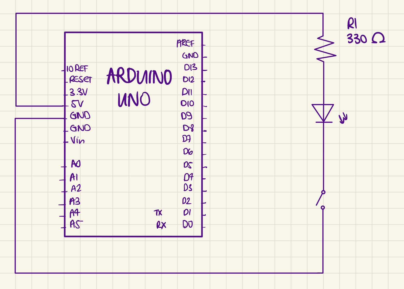
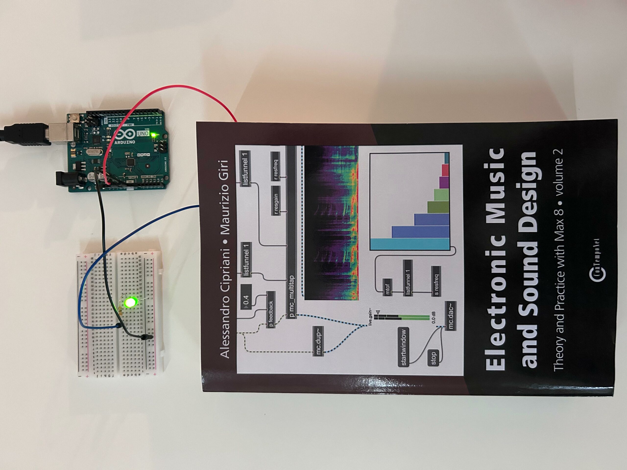
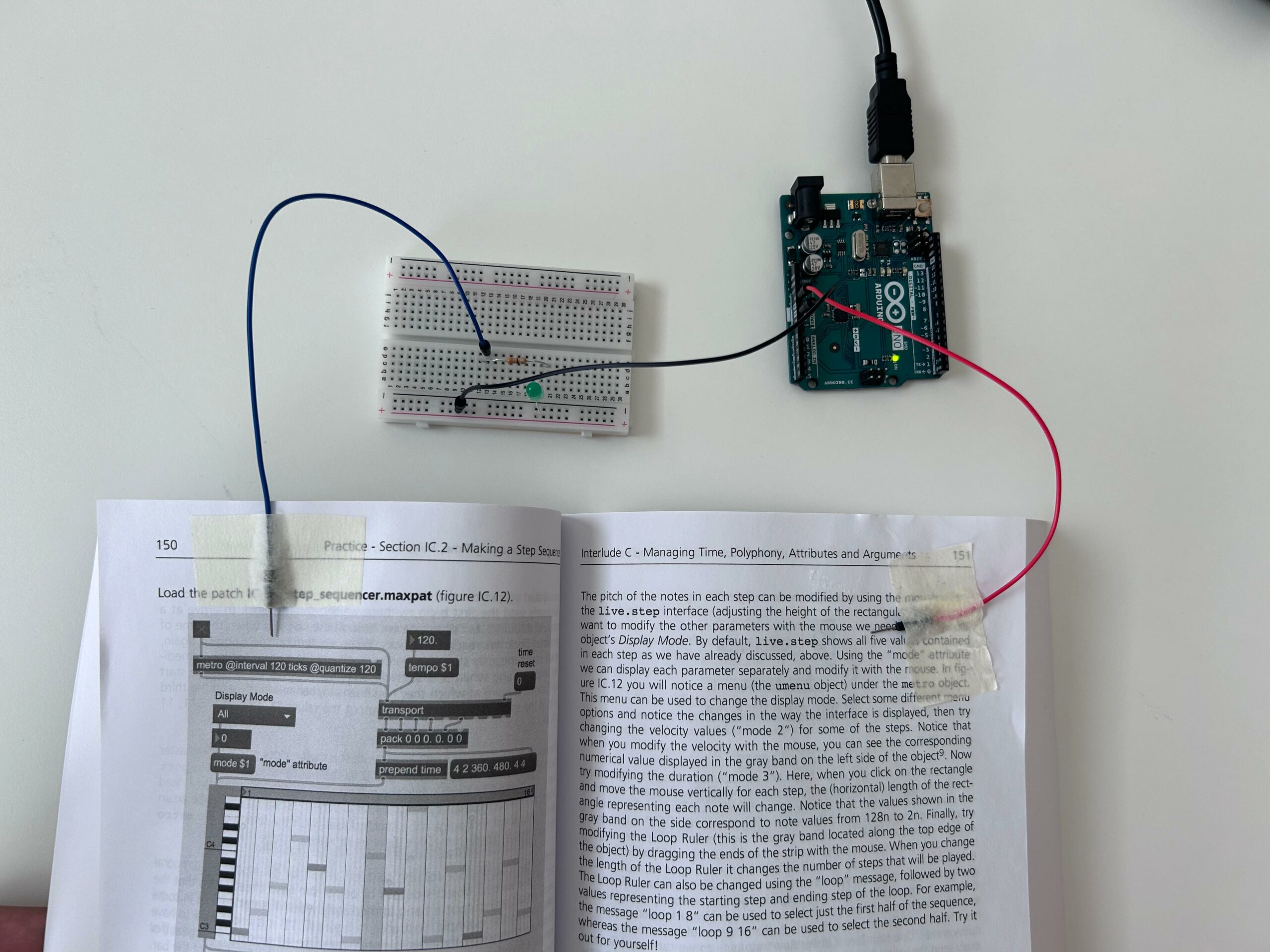
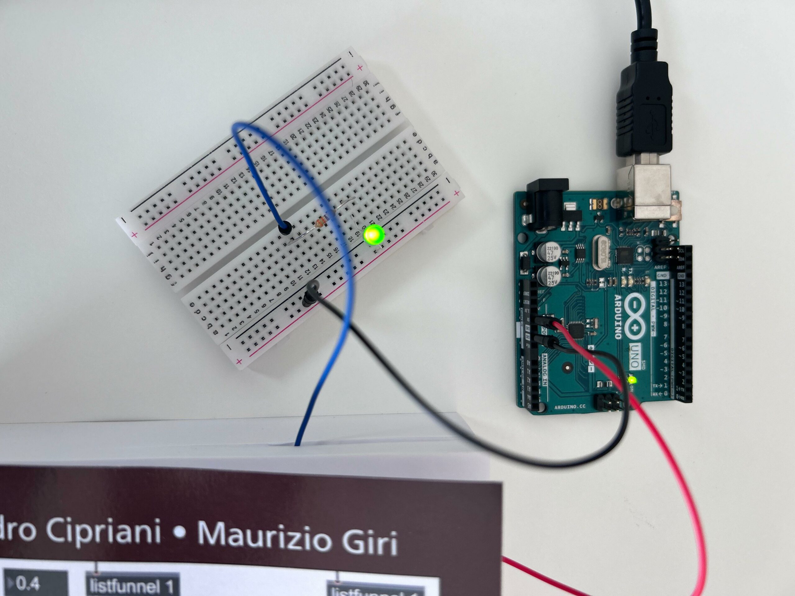
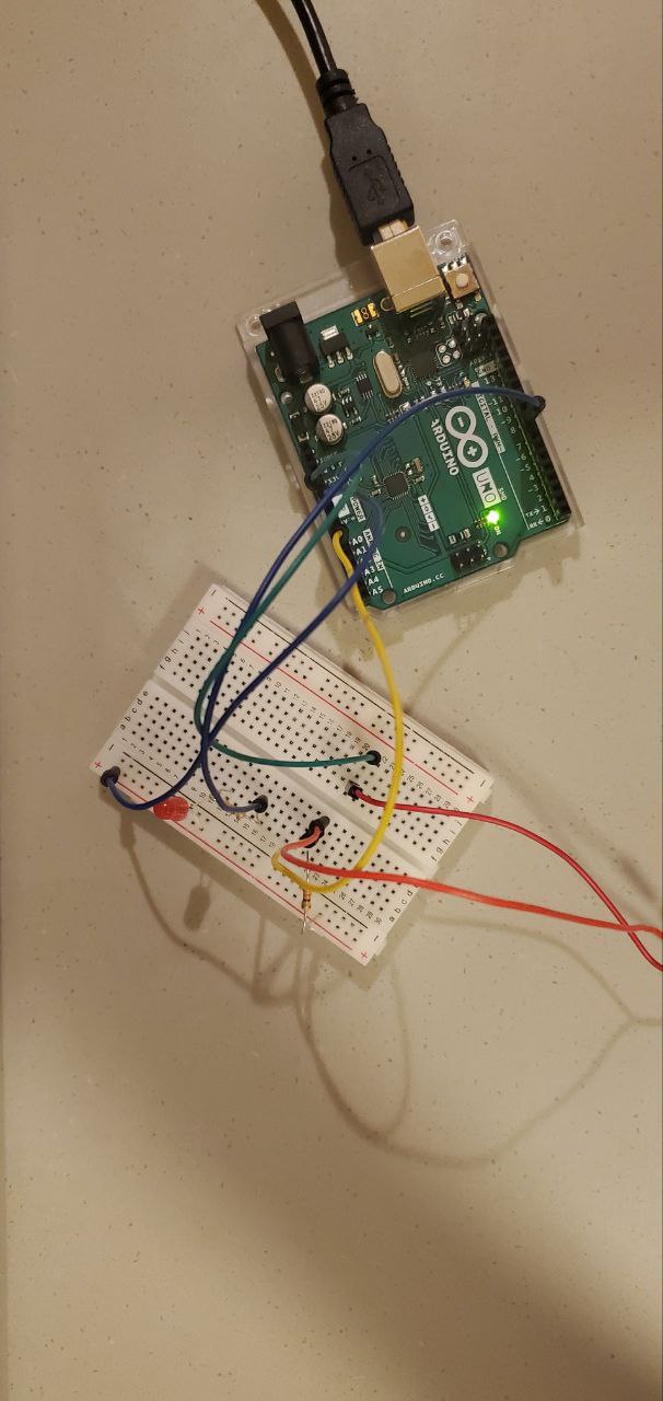
I was working on an Arduino project in my core class, where we were playing with the light sensor and I thought about this idea to use for my unusual switch. So basically an LED using a light sensor: it reads the light level, converts it to a simplified scale, and then turns the LED on in dark conditions and off in light conditions. The sensor measures how much light is in the environment. Based on this measurement, the Arduino decides whether it’s dark or light around. If it’s dark, the LED turns on to provide light. If there’s enough light, the LED stays off. This setup is a practical way to automatically turn a light on or off depending on the surrounding light level.

Video:

Code:

const int sensorPin = A0;
const int ledPin = 7; 

// Initialize the setup
void setup() {
  pinMode(ledPin, OUTPUT); // Setup LED pin as an output
}

// Function to read and process light level
int readAndProcessLight(int pin) {
  int sensorValue = analogRead(pin); // Read the light sensor
  // Convert the sensor reading from its original range to 0-10
  return map(sensorValue, 1023, 0, 10, 0);
}

// Function to update LED status based on light level
void updateLedStatus(int lightLevel, int threshold, int pin) {
  if (lightLevel < threshold) {
    digitalWrite(pin, HIGH); // Turn LED on
  } else {
    digitalWrite(pin, LOW); // Turn LED off
  }
}


void loop() {
  int lightLevel = readAndProcessLight(sensorPin); // Read and process light level
  updateLedStatus(lightLevel, 6, ledPin); // Update LED status based on light level

  delay(200); // Short delay to avoid flickering
}


Improvements:

I was trying to incorporate the idea of replacing one LED light with 3 LED lights. With an RGB LED to enable color changes based on light levels. For example, so different colors could indicate different intensities of the light, and I was testing with the sunlight that was falling from my window, from morning to evening.

W10 Reading Reflection

As a creative, I often see art as a form of self expression, a statement made by an artist to convey a message to an audience. Providing detailed interpretations of specific works, you could describe what each element, color, composition of the work means and how the audience should interpret it. That was the way I was taught to go about my practice, which I was also going to bring in when creating interactive projects for this class. However after reading Tigoe’s post about physical computing, I saw my perspective shift. Tigoe makes the point that interactive art is actually not about making a statement but about how the project is able to serve as an instrument or environment that invites the audience to engage , interact, and interpret it. This forced me to see art as a point of communication and not simply a form of expression. It opened my eyes to the reality that my role as a designer, creative or artist is to simply set the stage, provide the context, and then take a step back. It is only when this is done will the true beauty of art, but more specifically, interactive art, lie. Therefore, when creating one should try to prioritize setting the stage for dialogue, creating an environment that invites the audience to interpret and interact with the art as they wish. 

Reading Tigoe’s second blog post about physical computing’s greatest hits and misses allowed me to see my new found understanding in action. Tigoe showcased different projects from faculty and students alike that showcase the essence of interactive art that he preached about in the first blog I mentioned. What I found really interesting is that all of these projects, although they have instructions, give freedom for the user to engage with the project in the way they seem fit. For example, the Gloves project allows for users to make a rhythm by moving your hands or fingers in a particular way. Even if everyone engages with it, the rhythms they create and the way they decide to go about using the project varies greatly based on individual movements, interpretations, and interaction. To me, this reaffirms the idea that interactive art is never the same for everyone and that it thrives on two things: collaboration and personal interpretation. If these foundational principles are not at the forefront during ideation and creation stages of interactive projects, we are left questioning: is it truly interactive, or is it merely a static piece of art masquerading as interactive?


Week 9 Shaikha Alkaabi – Wink at me

My Project Idea:

I decided to build a project using an Arduino board that can detect when I wink. At first, I thought about making something that could sense how close my body was to a sensor. Later on in class, my teacher mentioned we shouldn’t use sensors for this project because that’s not what DigitalRead is about. So, I had to think of something else. That’s when I thought about how I often wink without even realizing it. I figured, why not turn that into my project? Surprisingly, setting up the breadboard, which I thought would be tough, turned out to be easier than I expected.

How It Works:

  1. Circuit Setup: I attached two small pieces of aluminum foil in a way that they sit close to my eye, one above and one below. These foils are connected to the Arduino board. I also connected a green LED to the Arduino, which acts as the output signal.
  2. Detecting the Wink: When I wink, the eyelid movement causes the two pieces of aluminum foil to touch. This touch closes the circuit, similar to pressing a button, but it’s my wink that makes it happen.
  3. Interacting With the Project: To interact with my project, all I have to do is wink. The aluminum foil pieces make contact, the Arduino notices the change, and the green LED lights up in response.
  4. Feedback: The lighting up of the green LED serves as immediate feedback that my wink was detected. It’s a simple and effective way to communicate the input action.
    Some challenges that I faced with this project are:
  1.  Getting the aluminum foil just right so it detects winks without false triggers from other facial movements was tricky.
  2. Keeping the foil safe and comfortable to wear around my eye needed thoughtful setup and possibly skin-friendly materials to avoid irritation which is why I opted to use a bandaid, which still seemed to irritated the area around my eyes.

Project Video:

IMG_5451 2


Hamdah AlSuwaidi – Unusual switch

For this assignment I have created a switch that activates an LED light when two jumper wires come into contact with a conductive liquid. Initially utilizing saltwater due to its well-known conductive properties, the project later incorporates laban, showcasing the project’s versatility and the unexpected utility of common substances in electronics. The switch operates on the principle that when the liquid completes the circuit between the two wires, the LED is powered on, demonstrating a basic but effective application of electrical conductivity and circuit design.

Concept:

The concept revolves around the exploration of electrical conductivity in liquids and the application of this property in creating an unconventional switch. Conductivity in liquids is often associated with the presence of ions. Saltwater, being rich in ions, is a good conductor of electricity. On the other hand, laban, while less conventional, also contains various salts and minerals that can facilitate the flow of electricity, making it a surprising but effective choice for this experiment.

How It Works:

Circuit Setup: The project utilizes an Arduino board as the control unit, a simple LED light as the output indicator, and two jumper wires inserted into two separate GPIO (General-Purpose Input/Output) pins on the Arduino. One of these pins is set up as an input to detect the circuit’s completion, while the other serves to provide a low voltage signal. The LED is connected to another GPIO pin on the Arduino, configured as an output.

Conductive Medium: The circuit is initially open, meaning the electrical path is incomplete, and the LED remains off. The introduction of a conductive medium (saltwater or laban) bridges the gap between the two jumper wires, allowing current to flow through the liquid and complete the circuit.

Detection and Response: When the Arduino detects the completion of the circuit through its input pin, it triggers the LED to turn on. This response acts as a visual indication that the circuit has been completed through the conductive medium.

Experimentation and Learning: By experimenting with different liquids like saltwater and laban, users can learn about the properties of electrical conductivity in a hands-on manner.

Video:

IMG_5445

Image:


WEEK 9 Unusual Switch + Documentation blog post Shereena AlNuaimi

I spent hours trying to think of a concept until it eventually occurred to me. To be very honest, I’m happy with the result, but I wanted to challenge myself further and attempt to learn more about Arduino. My original plan was not to blow a charm into the jumper cable to achieve the light produced by the LED, but since my code was crashing and my Arduino board stopped working all of a sudden, I had to modify my plan. I had to make the most of my limited time to do my task.

Naturally, investing a significant amount of time to complete this “unusual switch” project enabled me to become comfortable with the Arduino board concept overall. While this wasn’t how I intended to become familiar with it, the experience was still an eventful rollercoaster. Moreover, I decided to incorporate a very memorable part of my childhood a charm of the Arc De Triomphe. France was a huge part of my childhood and still is, something that everyone finds shocking is that my first language surprisingly was French (I know crazy right?). Furthermore, I wanted to combine a partial part of my life into this project as well.

Something I’d like to improve on in the future is trying to figure out why the brightness of my LED was so dim and not that bright. Overall, I’m pleased with the outcome, and the fact that I get to include something somewhat special was pleasing.

Unusual switch

const int led0 = 11; // LED connected to digital pin 11
const int touchSensorPin = 3; // Touch sensor (white wire) connected to digital pin 3

void setup() {
  pinMode(led0, OUTPUT); //LED as output
  pinMode(touchSensorPin, INPUT_PULLUP);
}

void loop() {
  if (digitalRead(touchSensorPin) == LOW) {  // if touch sensor detects physical contact
    digitalWrite(led0, HIGH); // Turn on LED
  } else {
    digitalWrite(led0, LOW); // Turn off LED
  }
}


Assignment #9 – Code – ☆Shine On☆

For this assignment, I didn’t have many ideas, so I was thinking about how to make the switch useful in a way. I thought of a few things, but then saw that my classmates had already done them, so I tried thinking of something else. That’s when it hit me! There is nothing I hate more than forgetting to wear my jewelry, particularly my rings. When I leave my room without them, I just feel… naked? However, one thing I never forget to do is to turn off the lights. I will always notice when a light is still on, unfortunately for me much more than when my rings aren’t. So, I thought, why not make a switch that is on when my jewelry is on it, and off when it isn’t? Obviously, this is a very small-scale prototype, but it was worth a try.


For the sake of the assignment, I only used one ring. It had to be a conductive material, so I picked a gold ring. Then, I created my circuit:


And here is a video demonstration:

IMG_1580

Finally, here is my circuit diagram:

Although it’s not a very complex circuit, I enjoyed creating it, particularly because I had missed two classes and wasn’t sure I had understood the process well. But I’m glad it worked out!


Week 9: Unusual Switch (LED Bookmark)

Concept:

When I was sitting on my desk thinking of ideas for this assignment, the first thing that came to mind was a book I saw right in front of me (which I’m relying on the most lately for my another class).

Then, I realized I actually don’t have a bookmark and every time I’m reading a book, I just write the page on my phone. So I decided to create kind of a “bookmark” that turn on the LED every time I close the book.

Materials:

  • 1 green LED light
  • 1 330 ohm resistor
  • A breadboard
  • An Arduino board with the 5V and Ground outputs
  • 1 red, 1 black, and 1 blue jumper wires
  • USB cable
  • Tape
  • My book

Demonstration:

Process:

The process of this circuit is really simple. Basically, I connected two jumper wires in the 5 V and Ground outputs of the Arduino. However, instead of connecting the 5 V directly into the breadboard, I pasted in one of the pages of the book. Then I used another jumper wire to do the connection between the resistor and the 5 V output.

Circuit

Reflection:

I’m really satisfied with the outcome of the assignment, especially because I think experimenting is one of the best ways to learn Arduino. So, I’m getting more familiar with the logic and the process itself. When it comes to areas of improvement, I intend to explore more other materials, as well as other ways of connecting the circuit.

Week 9 Assignment – Unusual Switch – Cheers

Inspiration

I first thought that it would be hard to find a case to switch the light bulb on without my hands but then the inspiration came to me when my friend sent me this emoji: 🥂. So I thought I could use water bottles to connect the circuit and switch on the light bulb. Which resulted in this:

Materials

    • A 330-ohm resistor
    • 1 LED light
    • A breadboard
    • One red and two black jumper wires
    • An Arduino board with a 5V and GND output
    • Cooper tape
    • Water bottles

Process and Results

Week 9 – Breathing Switch

For this week’s exercise, I decided to make a switch that will detect breathing.

The rudimentary mechanism that functions as a switch is two pieces of tin foil which are separated by a small gap. When a person breathes in, their chest expands, and the pieces of foil are separated. They connect when a person exhales.

The materials needed for this project are:

  • Breadboard
  • Arduino board
  • Tape
  • Jumper wires
  • Tin foil
  • 330-ohm resistor
  • 10K-ohm resistor
  • 1 LED light

Wires with tinfoil are stung around a person’s chest to connect around the chest. There is no danger to the subject as the voltage of the circuit is really low and cannot pass through a body.

/

When the circuit is closed, the Arduino detects the closure and sends a signal to an LED to light up.

The switch/sensor

The circuit:

Similar devices already exist in the medical field, and as a part of a lie detector machine.

While creating this project, it was really fun to think of the many potential real world applications that machines such as this, basically simple switches, have.

I ran into some problems with the sensor when I made this. It was really hard to make the sensor align with itself, and the shirt to which it was attached was flimsy and moved around, causing the sensor to go off at times it should not have. Ideally, the entire contraption would be accompanied by an elastic band which would go around the chest of a person to keep the sensors secure and aligned, or the sensor would be attached directly to the skin, via tape.

Raya Tabassum: Unusual Switch Project

Concept & Usage: My idea was to build a distance-sensitive security system. The system is designed to be sensitive to distance, using the HC-SR04 ultrasonic sensor paired with an Arduino board to trigger an audible alarm. The closer the object is to the sensor, the faster the alarm—or buzzer—will beep, which serves as an intuitive indicator of proximity.

The ultrasonic sensor-based alarm acts not only as a simple security device but can also be an interactive element for various applications. By emitting ultrasonic waves, the sensor can determine the distance to an object based on the time it takes for the waves to return. In the context of security, this setup can detect potential intruders or unauthorized access by sensing motion within a predefined range.

The versatility of the alarm allows it to be adapted for different purposes, such as:

  • Intruder detection for personal properties, alerting homeowners to possible trespassers
  • Industrial safety, where restricted areas can be monitored to ensure personnel safety
  • Public events, to manage crowd control and prevent attendees from accessing sensitive areas

Implementation:

When the system senses an object within a specified distance (less than 50 cm in your code), it activates the buzzer. The alarm’s operation is controlled by the code which defines the pins for the sensor and the buzzer, measures the distance by calculating the time interval of the echo’s return, and dynamically adjusts the beeping speed based on this distance.

Code:

//Security Alarm with Ultrasonic Sensor//

#define trigPin 6  
#define echoPin 5
#define buzzer 2
float new_delay; 


void setup() 
{
  Serial.begin (9600); 
  pinMode(trigPin, OUTPUT); 
  pinMode(echoPin, INPUT);
  pinMode(buzzer,OUTPUT);
  
}


void loop() 
{
  long duration, distance;
  digitalWrite(trigPin, LOW);        
  delayMicroseconds(2);              
  digitalWrite(trigPin, HIGH);
  delayMicroseconds(10);           
  digitalWrite(trigPin, LOW);
  duration = pulseIn(echoPin, HIGH);
  distance = (duration/2) / 29.1;
  new_delay= (distance *3) +30;
  Serial.print(distance);
  Serial.println("  cm");
  if (distance < 50)
  {
   digitalWrite(buzzer,HIGH);
   delay(new_delay);
   digitalWrite(buzzer,LOW);
 
  }
  else
  {
    digitalWrite(buzzer,LOW);

  }
  
 delay(200);
}
  • trigPin and echoPin are defined for sending and receiving the ultrasonic signals.
  • buzzer is defined for the alarm sound.
  • In the loop function, the program triggers the ultrasonic sensor and listens for the echo. The distance is calculated based on the time it takes for the echo to return.
  • The new_delay is calculated based on the measured distance. The closer the object, the smaller the delay, resulting in a faster beep.
  • The buzzer is activated if the object is within 50 cm of the sensor, with the beeping speed proportional to the object’s proximity.

References:

I used several Youtube tutorials for executing the project using the tools.

-https://youtu.be/HynLoCtUVtU?si=zHnjgYTF8wYnlOKp

-https://youtu.be/0Lhgd8PQmn0?si=OXr1fvTP4b9X0pPW