Week 10: Dual Hybrid Sensor Lighting System

Concept: For this project, I need to use both digital and analog sensors along with indicators like LEDs to get creative. After thinking about different ideas, I realized my inspiration is:  I’ve always wanted to upgrade my Marvel’s Moon Knight action figure. Just like in the comics, I want his face and symbol on his chest to light up red when it’s dark, giving a warning to criminals. I also want some background lighting, like thunder effects. So, I thought of using some cool LEDs and sensors to recreate this scene. To achieve this, I’ll be using a photocell as the analog sensor and a push button as the digital sensor.

Materials I used:
1. Arduino Uno Board
2. Breadboard
3. Two Leds (Red and Green)
4. Three 220 Ohm Resistors
5. Push Button
6. Photo-resistor (Light Sensor)
7. Jumper Wires

So the final circuit include all of these items, as well as my Moon Knight Action Figure.

Implemented Code with comments:

int led = 11; // LED pin connected to an analog sensor
int buttonPin = 2; // Button pin, using pin 2 for example
int buttonState = 0; // Variable for reading the push button status
int secondLed = 12; // Second LED pin, using pin 12 for example
bool blinking = false; // State to control the blinking

void setup() {
  Serial.begin(9600); // Starts the serial communication
  pinMode(led, OUTPUT); // Sets the led as an output
  pinMode(buttonPin, INPUT_PULLUP); // Initialize the push button pin as an input with an internal pull-up resistor
  pinMode(secondLed, OUTPUT); // Sets the second led as an output
}

void loop() {
  int sensorValue = analogRead(A2); // Read the value from the analog sensor
  Serial.println(sensorValue); // Print the value to the serial monitor
  analogWrite(led, map(sensorValue, 0, 1023, 255, 0)); // Write the inverted analog value to the LED
  
  int currentButtonState = digitalRead(buttonPin); // Read the current state of the push button

  // Check if button state has changed from high to low (button press)
  if (currentButtonState != buttonState && currentButtonState == LOW) {
    blinking = !blinking; // Toggle blinking state
  }
  buttonState = currentButtonState; // Update the buttonState
  
  // If the button was pressed, start blinking
  if (blinking) {
    digitalWrite(secondLed, HIGH); // Turn on second LED
    delay(250); // Wait for 250ms
    digitalWrite(secondLed, LOW); // Turn off second LED
    delay(250); // Wait for 250ms
  } else {
    // Turn off second LED when sensor value reaches 200 or more
    if (sensorValue >= 200) {
      digitalWrite(led, LOW); // Turn off LED
    } else {
      digitalWrite(led, HIGH); // Turn on LED
    }
  }
  
}

Video Demonstation:

Images:

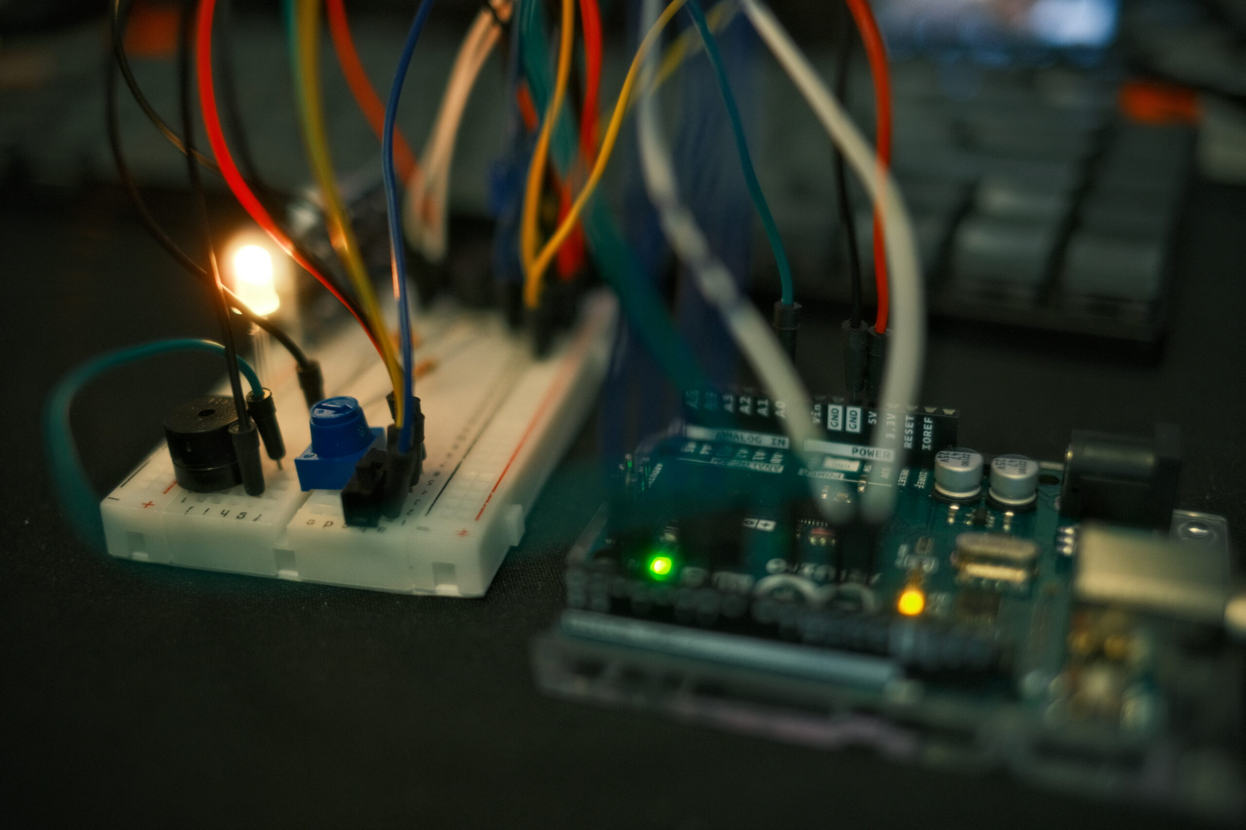
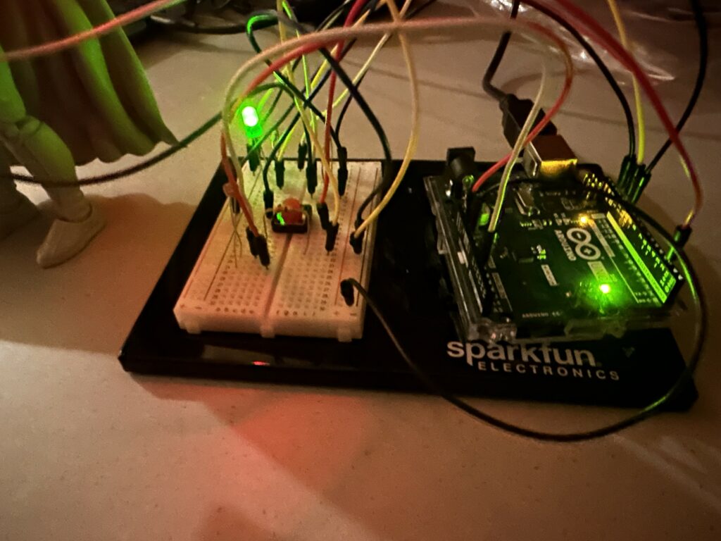
Figure 1.1: Closer View of the Circuit during Night time

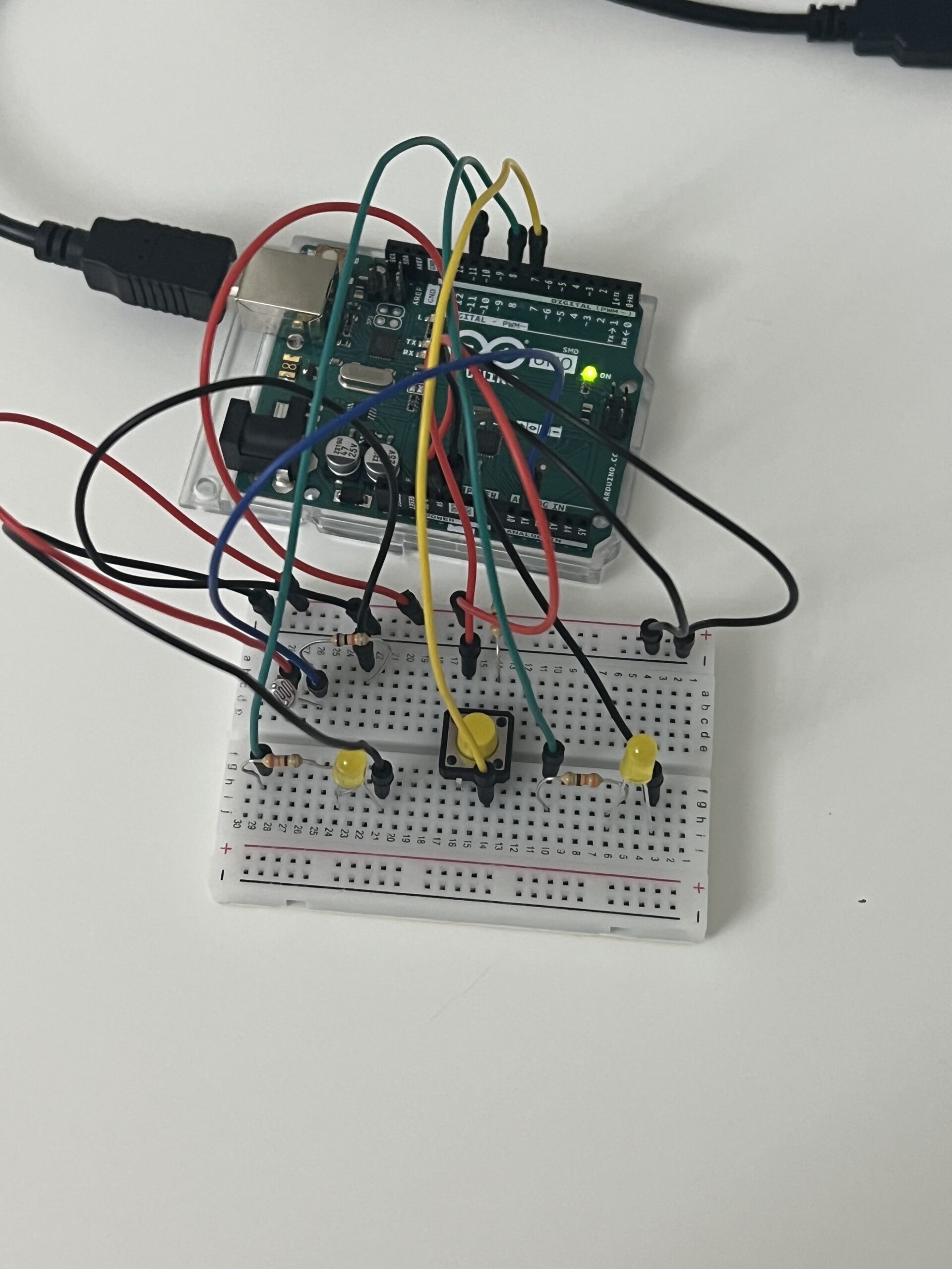
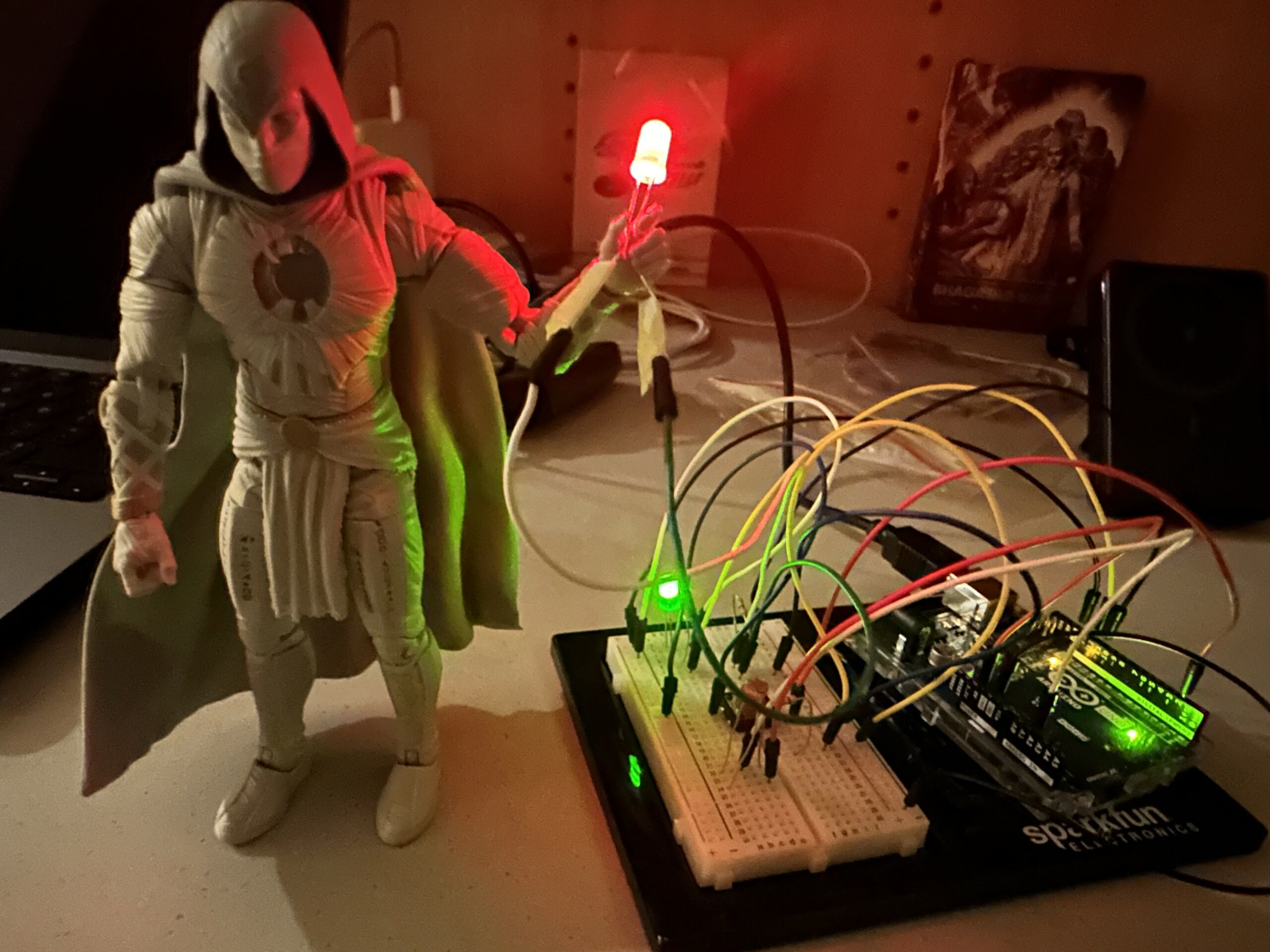
Figure 1.2: Complete View of the Circuit, Including with Action Figure. (Night Time)

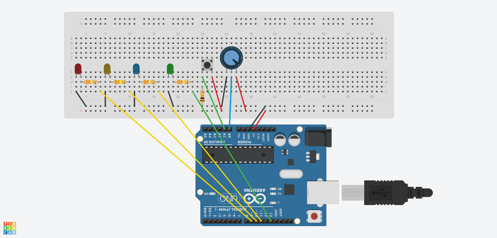
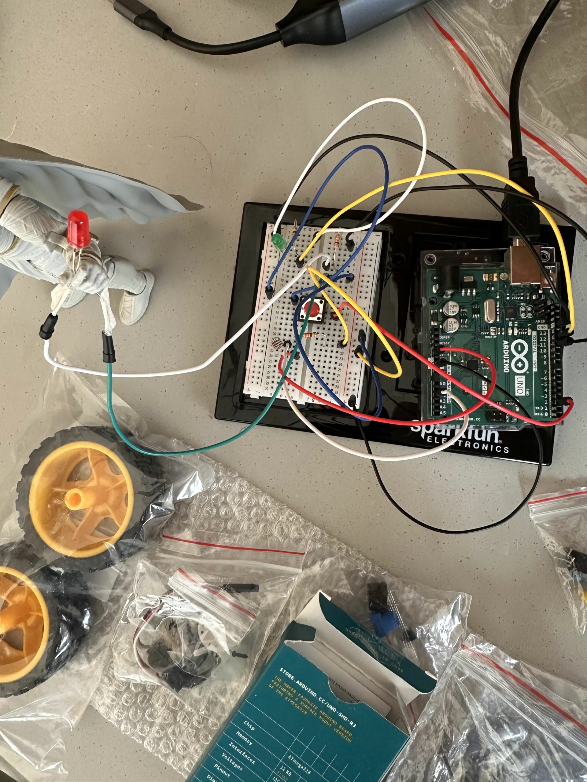
Figure 1.3: Top Angle View of the circuit during the Day time.

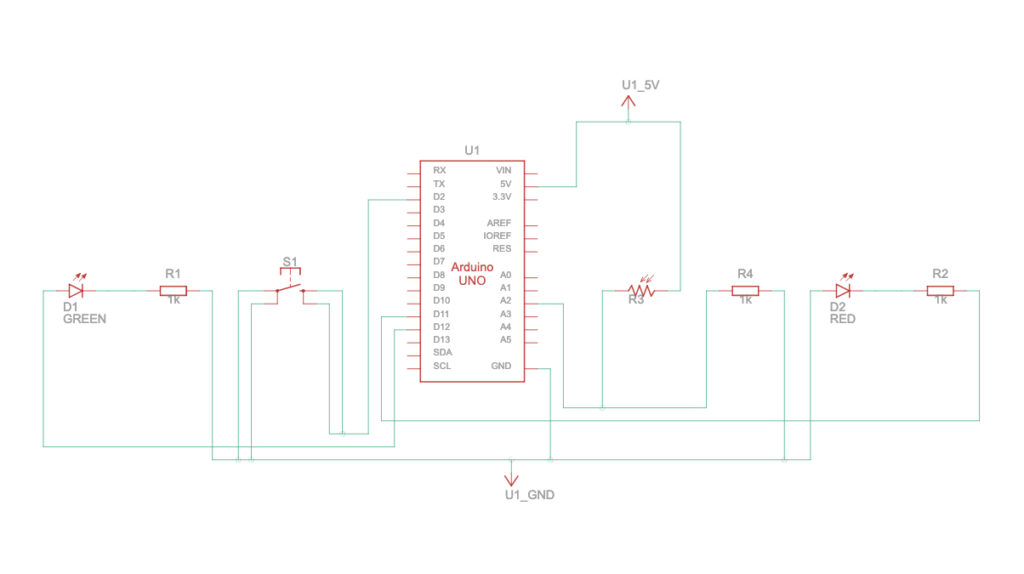
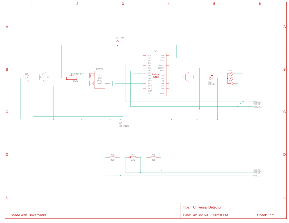
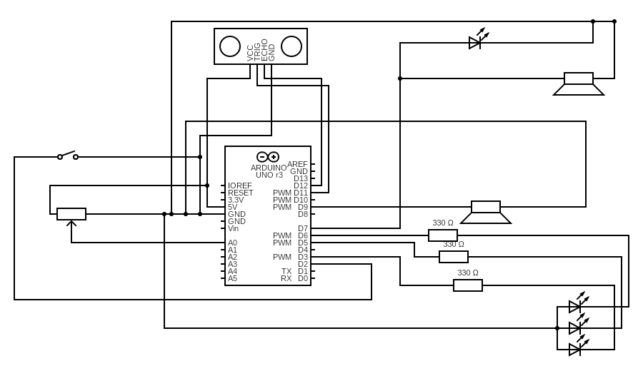
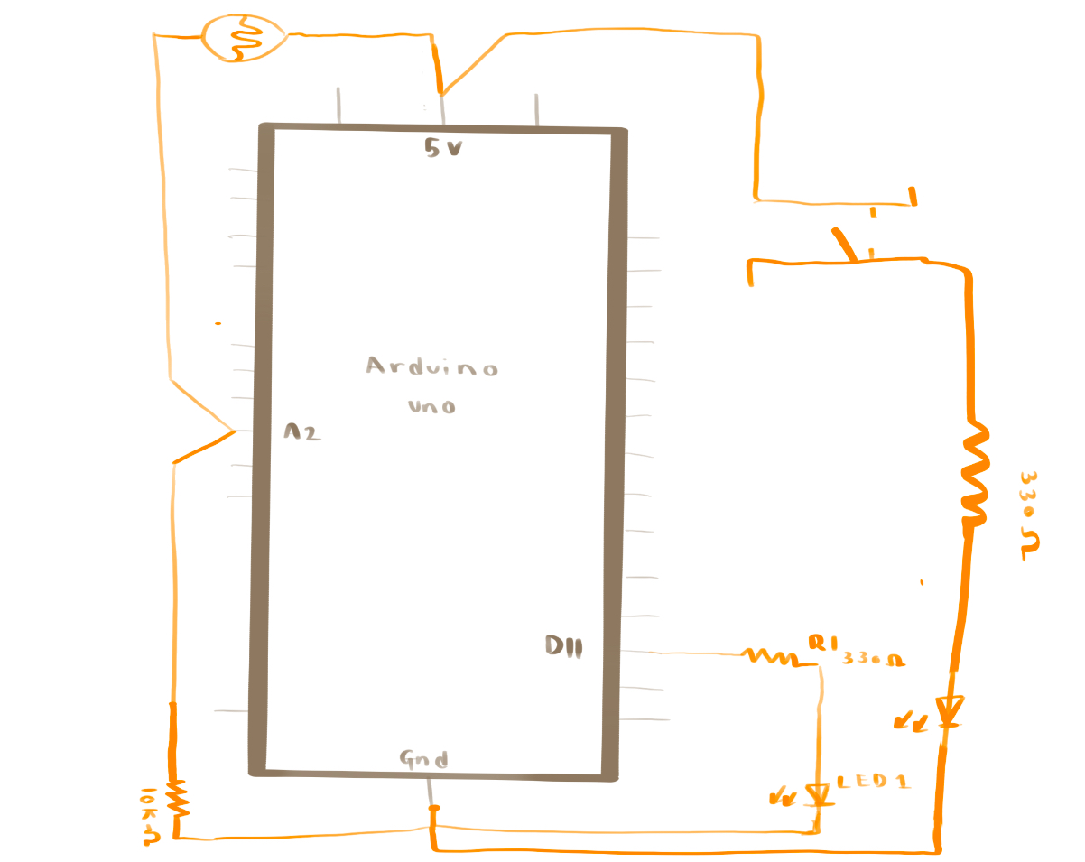
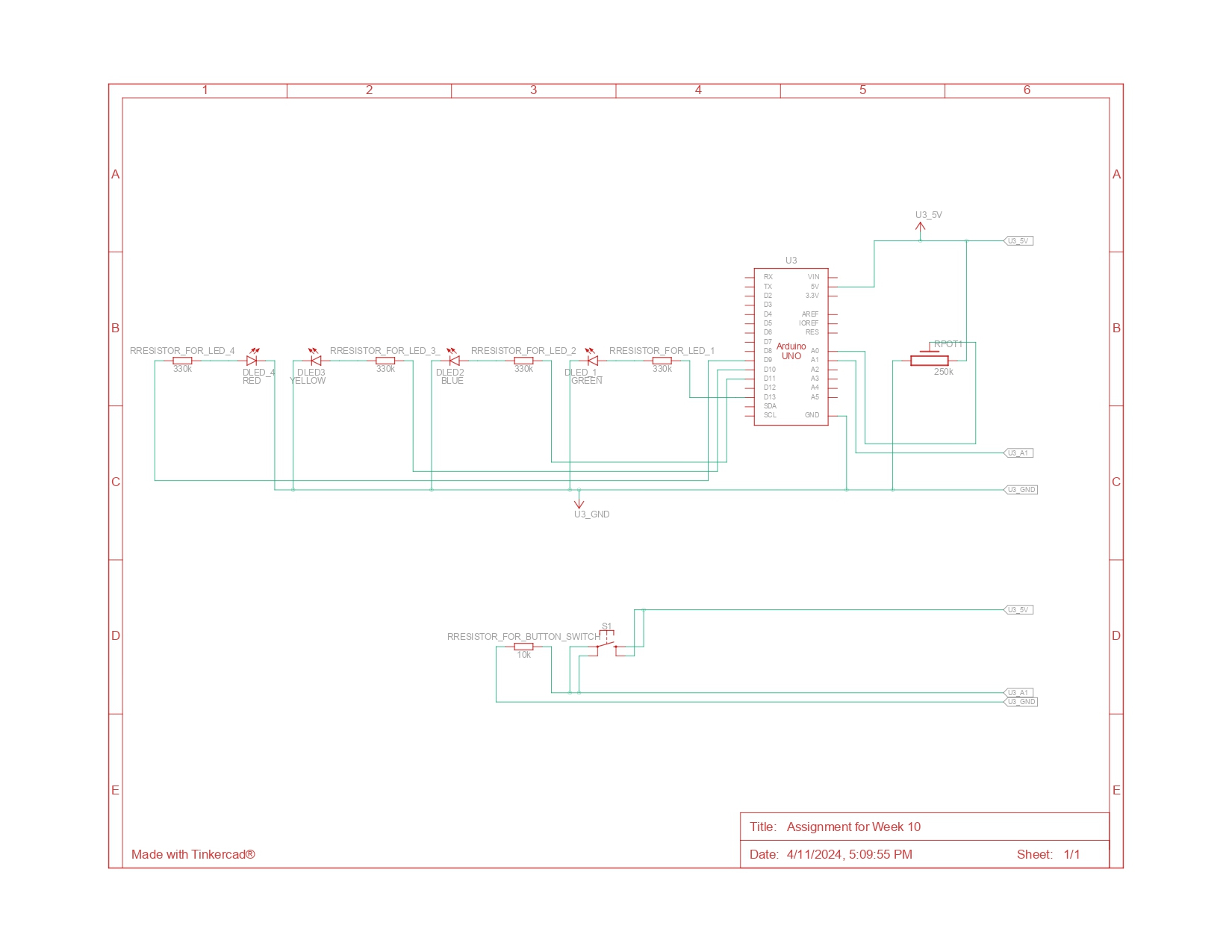
Sketch: Circuit Schematics

How circuit works:

LEDs and Resistors: There are two LEDs, a green and a red one. Each LED is connected to a digital pin on the Arduino (green to pin 11 and red to pin 12) through a resistor. The resistors limit the current to the LEDs to prevent them from burning out due to excessive current. The longer leg (anode) of the LEDs is connected to the resistor, and the other side of the resistor is connected to the Arduino pins. The shorter leg (cathode) of the LEDs is connected to the ground (GND) on the Arduino to complete the circuit.

PushButton:
The pushbutton has one side connected to 5V and the other side to both the ground (through a resistor) and to digital pin 2 of the Arduino. The resistor is a pull-down resistor that ensures the pin is at a known low signal when the button is not pressed. When the button is pressed, it connects the pin directly to 5V, giving a high signal. The internal pull-up resistor on the Arduino pin is activated in the code (INPUT_PULLUP), which means the pin is normally high, and pressing the button brings it to low. Moreover an analog sensor is connected to the analog pin A2 on the Arduino.

  • For the Green LED:  When the Arduino runs, it reads the value from the analog sensor connected to A2. This value is a measure of voltage that changes with the sensor’s readings. The Arduino then converts this reading to a corresponding brightness level for the green LED using analogWrite(), which uses pulse-width modulation (PWM) to simulate varying levels of brightness by quickly turning the LED on and off.
  • For the Red LED: The Arduino continuously reads the state of the pushbutton. When the button is detected as pressed (the signal on pin 2 goes from high to low due to the INPUT_PULLUP mode), it changes the blinking variable’s state. When blinking is true, the program  likely causes the red LED to turn on and off at certain intervals, simulating a blinking effect.

    Schematic Diagram Explanation:  Ultimately, the LEDs are represented by the symbols labeled ‘D1 GREEN’ and ‘D2 RED’. The resistors, labeled ‘R1’ and ‘R2’, are in series with the LEDs and connected to the digital pins on the Arduino symbol ‘U1’. The Arduino is central to the schematic and is labeled ‘U1’. All components are connected to it. It is shown with connections to power (5V and GND), the digital pins, and the analog pins. Hence the current flows from the 5V pin through the pushbutton when it is closed, and through the LEDs when they are enabled by the Arduino. Lastly this manages the flow by turning the pins to HIGH (5V) or LOW (0V) states and reading the voltage level from the analog sensor to determine the sensor’s readings.

Challenges and Reflection:
1) Connections of Jumper Wires: Connecting the wires to the action figure was a challenge because plastic tape doesn’t conduct electricity well. I had to ensure the ends of the jumper wires stayed firmly connected to the anode and cathode ends of the red LED without any loose connections. After some effort, I managed to secure the ends firmly with three to four pieces of tape.

2)  Push Button: The push button I used had a tendency to bounce (it has a loose connection with the bread board), causing unintended multiple presses. To solve this, first I implemented a delay in the code and they fixed the button with the help of screwdriver.

3) Photo-resistor Sensitivity and Range: The response of the photoresistor varied depending on the ambient light conditions. If the light levels fell outside the photo-resistor’s sensitive range, the LED wouldn’t respond as expected. To address this, initially I had to dim all the lights to make the room dark and I changed the range a bit limiting the sensor value from 400 to 250 then adjusted the code to accommodate my room lighting conditions, ensuring consistent LED performance.

Future Improvements:
a) I have an improvement in mind for the blinking green light in the background. Currently, it blinks manually with a delay of 250 ms. However, I want to integrate it with the background system so that when there’s a high pitch, the green background LED lights up brighter, and otherwise, it remains constantly low.

Overall, despite the hours spent on connections and coding, I’m satisfied with the outcome of the project. It feels completely worthwhile to recreate the scene of my favorite superhero from the comics! In the future, I’d love to enhance it further with more LEDs and sensors.
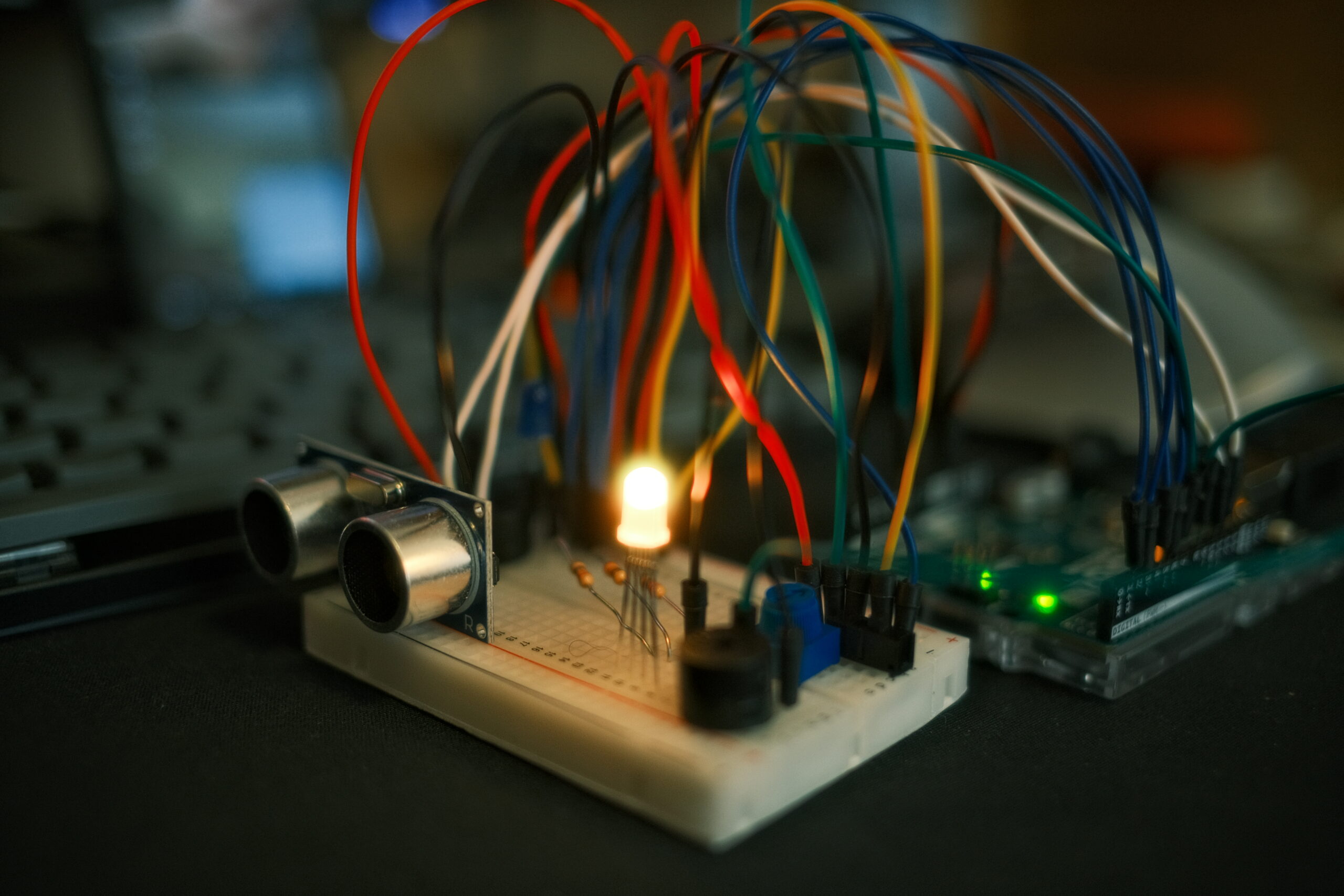
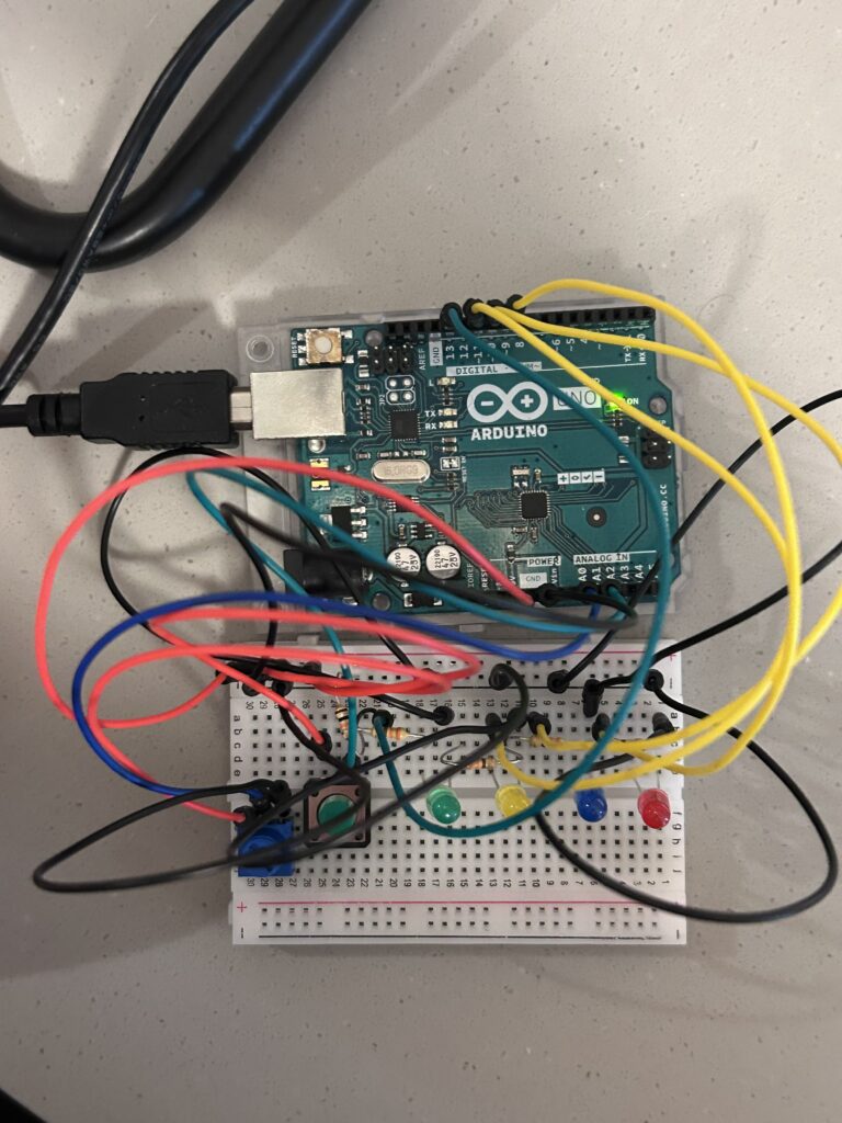
 

Week 10 Response Dachi

The articles “Physical Computing’s Greatest Hits (and Misses)” and “Making Interactive Art: Set the Stage, Then Shut Up and Listen” provide many insights and advice for artists and designers who want to create interactive physical computing projects and installations.
In “Physical Computing’s Greatest Hits (and Misses)”, the author reviews some of the most common themes and project ideas that take place in physical computing classes. What stood out to me is how he encourages students not to be discouraged if their ideas have been done before. As he points out, these themes are popular precisely because they offer room for originality and surprising variations. Even if the core interaction (e.g. theremin-like instruments, gloves, floor pads) has been explored, there are always opportunities to put new spins on it through the specific form, aesthetics, narrative, and context.
His different project types made me reflect on my own tendencies and biases when brainstorming IM concepts. I tend to gravitate toward certain projects which have the most creative and interesting aspects in sight. I don’t want to just satisfy assignment requirements but have the project with a certain goal in mind to have a certain effect on the user.
“Making Interactive Art: Set the Stage, Then Shut Up and Listen” article offers advice that somehow conflicts with my instincts as a designer. Author advises interactive artists to avoid pre-scripting the participant’s experience and interpretations. Let the audience discover meaning for themselves through open-ended interaction with the work.
This is quite different from other design contexts like UX, where the goal is often to carefully guide the user through a curated experience towards a specific goal. But with interactive art, you get more authentic audience engagement and emotional resonance by leaving room for ambiguity, surprise, and personal interpretation. It requires the artist to give up some control, which can feel uncomfortable. But the end result is a richer dialog between the artist and the audience. For example, when I was designing my midterm project, I left players with a choice (e.g. pick up the ring or not) so players could act accordingly. For communications lab projects, we also try to design concepts that actively consider user input (e.g. alternating storyline and so on). I still feel like there is some level of prediction that needs to happen, nothing is truly open world experience as we don’t have enough resources or computing power for that, but we can try to get as close as possible.
Author’s advice to “shut up and listen” – pay close attention to how people interact with and react to the work – also struck me as highly relevant to interaction design in general, not just artistic contexts. We can learn so much by observing where our creations fail to improve in the future. Therefore, staying open to that feedback is essential for refining the work. This is something I did for my midterm as well by asking my friends to play game and provide constructive criticism.
In conclusion, these two articles provide many thought-provoking ideas to anyone trying to overcome the challenges of creating meaningful interactive experiences. While some of the advice may be particular to media art contexts, much of it feels widely applicable to interaction design as a whole. These are things I already take into account in my assignment, and now I feel even more aware moving further into complex projects.

Multidetector – Week 10 – Dachi Tarughishvili

Introduction

For this assignment I really wanted to use Ultrasonic sensor and experiment with its detecting capabilities, hence the name of the project – multi-detector. I wanted to have three separate distances: near, medium, far to have different activations. (For example, different lights or sounds). To satisfy projects requirement (analog input/output + digital input/output) I decided to implement other elements since ultrasonic can be considered as both. This enabled me to expand project and make it more interactive. I decided to add RGB LED as an analog output source which in itself is based on ultrasonic sensor readings. A digital output LED in this case would be the status LED which is activated by digital input slider switch. Conversely, the status is also indicated by short lasting sound by second piezo speaker. The analog input is my potentiometer which controls the pitch of the buzzer. As you can see we have more than one digital/analog inputs and outputs and making sure they all work well together in a sensible manner was the main goal of this project.

Process:

The design is quite intuitive. User can turn on the sensor which is indicated by blue led briefly lit up and brief sound played by second piezo speaker. Then user can point the ultrasonic sensor at different objects. RGB LED will light up in different colors based on the distance to that object. For far distances I am using green light, for medium – yellow and for close red. I decided to use RED for close along with buzzing sound to demonstrate a state of emergency, something that is often used in real life applications. Providing both striking visual stimulus (RED color) and audio (high pitch sound) signals the user of proximity in urgent manner. This might be useful for larger scale projects where detection of a foreign object has to be alerted to user at all costs.

I used Tinkercad for simulating my project online and as seen on the video below, it works perfectly fine: (I tried to rearrange objects for best visibility possible).

simulation

I am also including a diagram form Tinkercad conversion which did not look fully proper with incomplete connections and questionable alignments, hence I used Circuit Diagram Web Editor to draw design myself from scratch (ultrasonic is in center since it has both inputs and outputs). For the future assignment I will only use whichever is most appropriates based on your feedback.

Code:

// pin connections
const int trigPin = 11;               // Pin connected to the trigger pin on the ultrasonic sensor
const int echoPin = 12;               // Pin connected to the echo pin on the ultrasonic sensor
const int redPin = 3;                 // Pin to control the red LED inside the RGB LED
const int greenPin = 5;               // Pin to control the green LED inside the RGB LED
const int bluePin = 6;                // Pin to control the blue LED inside the RGB LED
const int piezoPin = 9;               // Pin for the first piezo speaker (used for siren)
const int potPin = A0;                // Analog pin connected to the potentiometer
const int switchPin = 2;              // Digital input pin for the switch
const int secondPiezoPin = 7;         // Pin for the second piezo speaker (used for feedback on switch toggle)

float distance = 0;                   // to store the measured distance
bool lastSwitchState = HIGH;          // to track the last state of the switch

void setup() {
  Serial.begin(9600);                
  
  // Set pin modes
  pinMode(trigPin, OUTPUT);
  pinMode(echoPin, INPUT);
  pinMode(redPin, OUTPUT);
  pinMode(greenPin, OUTPUT);
  pinMode(bluePin, OUTPUT);
  pinMode(piezoPin, OUTPUT);
  pinMode(secondPiezoPin, OUTPUT);
  pinMode(potPin, INPUT);
  pinMode(switchPin, INPUT_PULLUP);   // internal pull-up resistor for the switch
}

void loop() {
  bool currentSwitchState = digitalRead(switchPin); // read the current state of the switch

  // check if the switch state has changed
  if (currentSwitchState != lastSwitchState) {
    if (currentSwitchState == LOW) {
      // plauy a brief sound on the second piezo speaker when the switch is toggled
      tone(secondPiezoPin, 1000, 200); //  a 1000 Hz tone for 200 milliseconds
    }
    lastSwitchState = currentSwitchState; // Update the last known state of the switch
  }

  // actions when the switch is active
  if (currentSwitchState == LOW) {
    distance = getDistance(); //  distance - ultrasonic sensor

    Serial.print(distance);
    Serial.println(" in");

    //  RGB LED control
    if (distance <= 10) {
      analogWrite(redPin, 255);       // Close distance - turn RGB LED red
      analogWrite(greenPin, 0);
      analogWrite(bluePin, 0);
      playSiren();                    // siren on 
    } else if (distance > 10 && distance < 20) {
      analogWrite(redPin, 255);       // Medium distance - turn RGB LED yellow
      analogWrite(greenPin, 50);
      analogWrite(bluePin, 0);
      noTone(piezoPin);               // Stop siren
    } else {
      analogWrite(redPin, 0);         // Far distance - turn RGB LED green
      analogWrite(greenPin, 255);
      analogWrite(bluePin, 0);
      noTone(piezoPin);               // Stop siren
    }
  } else {
    // Turn off all outputs when the switch is not active
    analogWrite(redPin, 0);
    analogWrite(greenPin, 0);
    analogWrite(bluePin, 0);
    noTone(piezoPin);
  }

  delay(50);  // Short delay to stabilize readings
}

// Function to measure distance using ultrasonic sensor
float getDistance() {
  digitalWrite(trigPin, HIGH);
  delayMicroseconds(10);
  digitalWrite(trigPin, LOW);

  float echoTime = pulseIn(echoPin, HIGH);
  return echoTime / 148.0;  // Convert time to distance
}

// control siren based on distance
void playSiren() {
    int potValue = analogRead(potPin);  // read the potentiometer value
    int volume = map(potValue, 0, 1023, 0, 255);  // Map it to PWM range
    analogWrite(piezoPin, volume);  // control volume

    
}

In the setup() function, each component is initialized to its respective pin mode, ranging from outputs for LEDs and piezo speakers to inputs for the ultrasonic sensor and potentiometer. The main loop() continuously checks the state of a digital switch to control the overall system operation, toggling functionality and triggering a brief alert sound from a secondary piezo speaker upon state changes. Distance is measured using an ultrasonic sensor, with the results dictating the color output of an RGB LED and the activation of a siren on the primary piezo speaker, whose volume is adjusted by a potentiometer. Everything else I already discussed in introduction and commented in the code. As you can see it is quite extensive so hopefully it should answer all your questions.

Demonstration:

Challenges:

While integrating the various components in this project, I faced some interesting challenges. Managing the piezo speaker’s volume with analogWrite() proved to be tricky because the function doesn’t directly control voltage output but instead modulates the PWM signal, which isn’t ideal for driving piezo speakers. I followed a tutorial for setting up an ultrasonic sensor from Sparkfun itself so that was fairly straightforward. I tried my best to manage the colors of the cables properly but eventually, I ran out of black wires so I used yellow as a substitute. Redrawing schematic was not as much challenging as it was time consuming. In the future, I would like to find a faster way to do this while satisfying project requirements.

Reflection:

All in all, I am quite happy with how my project turned out. I think what I learned through this project might be very useful for my future assignments and final project since I learned more about digital/analog inputs outputs as presented in Arduino, as well as reading/creating schematics and testing out project both in simulation and in real world. This project could easily be expanded by incorporating more components and making it part of something bigger since its sole responsibility for now is just detection.

W10- Dual Lighting System Using Digital and Analog Sensors

As I am still experimenting with physical computing and coding for Arduino, I tried to emphasize simplicity for this week’s assignment. The concept for this week’s assignment is a simple lighting system using both digital and analog sensors. This lighting system has two LEDs, one attached to a manual system while the other an automatic one. This gives users the freedom to either choose to use only one light system or both. I was inspired to create this dual lighting system because I often feel like versatility in lighting is important not only to give a space more dimension but to also make our lives easier. With such a system, users are able to ensure that they have the right lighting for the circumstance they are in but also have the freedom to control it the way they see fit. Below you can find the schematic diagram of the system I created:

(warning, schematic diagram might not be comprehendible!)

After finalizing the schematic, I began building the actual system using the Arduino uno. The components used in this assignment were 11 wires, 2 LEDs, one button, one photo-resistor, 1 10K resistors, and 3 330 resistors. These components helped to create an efficient dual lighting system that helps users have a good balance between manual control and automatic adjustment of the lighting. I pinned the 5v and the ground to the positive and negative ends of the bread board to act as a “main ground” for the rest of the circuits on the bread board. For the button part of the circuit, I placed one end of the red wire to connect to the positive end of the board and one end of the 330 resistor. The other end of the 330 resistor is placed at the negative end of the bread board to ground it. The wire attached to 5v is attached to one end of the button, while the other end of the button is attached to pin 7. This wire is connected to another 330 resistor, which is attached to the LED A that is used for the “manual” system. The other end of LED A is grounded in the negative end of the bread board. For the photo-resistor, one end of it is attached to the positive end of the bread board where 5 voltage is. The other end of the photo-resistor is a wire that is attached to A1, which is an analog pin. That wire is connected to a 330 resistor. One side of the resistor connects to the wire that is connected to the negative end of the bread board where it is grounded. For LED B, which is the automatic part of the circuit, one side is connected to the negative end of the bread board where it is grounded and the other side is connected to a 330 resistor. The other end of the 330 resistor is connected to a wire, which is attached to pin 11. This makes the full manual and automatic light system. Below, you can find an image of the built system based off of the schematic diagram:


Programming the LEDs to function as intended required code for each. The first LED was programmed to turn on and remain on when the button was pressed and off and stay off when the button was pressed again, representing the digital sensor aspect of the system. The second LED was designed to activate and deactivate automatically in response to the light levels detected by the photo-resistor, which represents the analog sensor aspect of the system.  While the automatic adjustments based on the light levels might appear to be the most complex part of the system, it was actually the digital control of the first LED that presented the most challenges. I had to review class materials several times, go over examples, and watch youtube videos to get to the vision I wanted to have for this system. The youtube video that ultimately helped me to get to the vision I wanted was Robotics Back-End’s Arduino- Turn LED On and Off With Push Button video, which has been cited  at the bottom of this blog post. Therefore, that is one part of code that I am particularly proud of. 

void loop() {
//BUTTON
int buttonState = digitalRead (7);
// Check if enough time has passed since the last button state change
if (millis() - lastTimeButtonStateChanged >= debounceDuration){
   // Check if the button state has changed
  if (buttonState != lastButtonState){
    // Update the last time the button state changed
    lastTimeButtonStateChanged = millis();
    lastButtonState = buttonState;

    // Toggle the LED state when the button is pressed
    if (buttonState == LOW){ //If button is not pressed
      if (ledState == HIGH){ //and LED is on,
        ledState = LOW; //make LED turn on
      } else{ //if button is pressed,
        ledState = HIGH; //Make the LED turn on
      }
       // Update the LED controlled by the button
      digitalWrite(8, ledState);
   }
  }
 }
}

As you can see, the code corresponding to the button is intricate, utilizing a lot of ‘if’ statements to achieve the desired  on and off effect when the button is pressed. You can see this and the whole system in action below:  

In terms of improvements, I would have definitely liked to have only one LED to make it as similar to a typical light system as possible. I initially thought of coding one LED to have both the manual and automatic light systems but I, unfortunately, was not able to get it to function the way I wanted it to. Therefore, that is something I would like to improve on for the future. However, I have to say even with the countless days spent on this assignment, I genuinely enjoyed getting to the final product and seeing my vision come to life some way or another. As I mentioned earlier in this blog post, I was still adjusting to physical computing and using Arduino, which is why I wanted to create something simple. Creating this lighting system, although simple, was a big step into seeing not only the ways in which you can use physical computing components to create things that you envision but it has also allowed me to see the ways in which it can be used to fix real world problems. Even if this was obvious to me, it was only when I started to create things of my own did I see the potential and reach of physical computing in helping fix many of the problems people are facing today, which is something I am glad to have seen for myself. 

References: 

[Robotics Back-End]. (2022, February 28). Arduino – Turn LED On and Off With Push Button [Video]. Youtube. https://www.youtube.com/watch?v=ZoaUlquC6x8

Afra binjerais – Week 10 assignment

In order to demonstrate both digital and analog input processing, my project uses an Arduino Uno to control two LEDs depending on input from an analog photo resistor and a digital pushbutton. The circuit consists of a pushbutton that activates the system when pressed and a photoresistor that controls the state of a red and a green LED by measuring the amount of ambient light. Pressing the button causes the system to come alive, activating a flag that maintains the LEDs’ responsiveness to light variations. The green LED shines in brighter lighting, while the red LED flashes in low light to signify darkness.

This is my code:

// Define pin numbers
const int buttonPin = 2;     // Digital pin connected to the button
const int redLEDPin = 3;     // Digital pin connected to the red LED
const int greenLEDPin = 4;   // Digital pin connected to the green LED
const int photoResistorPin = A0; // Analog pin connected to the photoresistor

bool ledsActive = false;  // State variable to keep track of LEDs' activity

void setup() {
  pinMode(buttonPin, INPUT);
  pinMode(redLEDPin, OUTPUT);
  pinMode(greenLEDPin, OUTPUT);
}

void loop() {
  int buttonState = digitalRead(buttonPin);
  int lightLevel;

  // Check if the button is pressed
  if (buttonState == HIGH) {
    ledsActive = true;  // Remember that LEDs should be active
  }

  // Control LEDs based on the 'ledsActive' state
  if (ledsActive) {
    // Read light level from the photoresistor
    lightLevel = analogRead(photoResistorPin);
    
    // Determine which LED to keep on based on light level
    if (lightLevel < 512) {  // Threshold for light level can be adjusted
      digitalWrite(redLEDPin, HIGH);  // Turn on red LED if dark
      digitalWrite(greenLEDPin, LOW); // Turn off green LED
    } else {
      digitalWrite(redLEDPin, LOW);   // Turn off red LED if bright
      digitalWrite(greenLEDPin, HIGH); // Turn on green LED
    }
  } else {
    // Turn off both LEDs if the LEDs should not be active
    digitalWrite(redLEDPin, LOW);
    digitalWrite(greenLEDPin, LOW);
  }
}

And this is the setup of my Arduino:

I really enjoyed playing around with the photoresistor in this project and seeing how variations in the surrounding light dynamically affected the LEDs’ behavior, providing a concrete example of how electronic components interact with their surroundings. In addition to adding another level of interest, this investigation into light sensitivity helped me gain a deeper comprehension of analog sensors. Nevertheless, I did struggle with a couple of things. At first, I had trouble wiring the circuit correctly and dealing with connections that were wrongly placed in incorrect places on the breadboard. Even though they were annoying, these errors taught me a great deal about circuit design and debugging and made me realize how important it is to pay close attention to detail when working with electronics.

Please view the video to visualize how my project works:

Reading Reflection – Week 10

Physical Computing’s Greatest Hits (and Misses)

This reading was particularly informative, offering a wide array of projects within the field of physical computing. Previously, I had never imagined that such diverse and innovative projects were feasible when I first began my journey in this field. Particularly, I was fascinated by the idea of the theremin. This was a project I had wanted to work on when I was enrolled in another class last semester. However, due to my limited knowledge at the time, I couldn’t bring my ideas to reality. Now, equipped with the skills I’ve acquired from our recent classes, I feel confident and excited about the possibility of making this project a reality. The potential to combine electronic components with musical creativity truly captures the essence of what makes physical computing so exciting.

Making Interactive Art: Set the Stage, Then Shut Up and Listen

I really liked the directness and clarity in the title of the article. It reflects a fundamental truth about design: designers are communicators, not merely speakers. They show their thoughts through their creations. As the article discusses, Interactive Art goes beyond traditional boundaries by transforming viewers into active participants. This dynamic completes the artwork, creating a shared authorship between the creator and the audience. My experience last summer in a South Korean museum demonstrated this concept. There, I saw an interactive installation where visitors could draw animals and scan them to integrate their creations into the larger display with a pre-created background. This not only made the artwork dynamic but also personal, as each visitor’s contribution became central to the artistic narrative. It was a vivid demonstration of the profound connection that interactive art can forge, drawing beauty from the synergy between the artist’s vision and the audience’s involvement.

Week 10 | Creative Reading Response

“Physical Computing’s Greatest Hits ” was a very interesting and thought provoking article . It talks about different forms of Interactive projects related to physical computing . Several interesting ideas were presented . It provoked me to think about ideas for my IM Final project. Ideas such as the hands-as-cursor and the glove are really interesting to me and I hope I can build something inspired by them for my Final Project. Ideas like these that turn the human hand into a method for controlling an object or a screen is something I would love to work on . 

“Making Interactive Art” focuses more on the role of us as designers to create an experience of discovery for the user .The idea that the main goal is not to create an entire conversation but rather to start a conversation is something I would like to keep in mind while designing something interactive . This ties well with the idea of signifiers by Don Norman in the previous readings.  The idea of art that inspires rather than conveys has always been appealing to me. This notion of taking the user through a journey rather than specifying a fixed way of interacting with the work reminds me of the phrase “The journey is more beautiful than the destination ” . I hope to keep this in mind in my upcoming projects . 

Week 10: Response on Physical Computing and Interactive Art Readings

Physical Computing Greatest Hits and Misses

I agree with the author’s description in the article that when someone is learning physical computing and is required to come up with project ideas, people sometimes just eliminate most of the ideas just because they thought that it has already been done before. While there is plenty of room for variety and enhancement, it can lead to an entirely new concept. In short, I found the author’s insight firmly aligned with the concept of ‘standing on the shoulders of giants’. And I think this is an amazing realization that one must have since innovation always comes out when individuals stole the ideas that are worth stealing and left behind others that are not attractive to them and then built something that is entirely new.

Two interesting technologies that were mentioned in this article that I like the most were the Gloves and the Hand-as-cursor. The way the drum gloves are designed on the interface of the gestural language, producing discrete musical notes though simple finger taps shows the integration of force-sensing resistors and flex sensors in the Power Glove to detect movement and gestures. This idea seems to be intriguing yet complex, as it captures the challenge of translating simple, intuitive human actions. I believe the complexity is not only in the technological implementation but also in ensuring that the user experience remains interesting and simple. This technical conversation causes me to reflect critically on the balance between technology and the simplicity required for widespread user acceptance. This thinking leads me to draw parallels with the evolution of touchscreen technology, particularly its incorporation into mobile devices. Initially, touch screens were a novel technology that some saw as gimmicky; nevertheless, their design centered on natural human actions, such as swiping and tapping, which led to widespread adoption. This “intertext” identifies a vital path for me from innovation to integration, underlining the necessity of user-centered design in technology.

Despite the advances these themes represent, they raise concerns about the extent to which such interfaces can replace more traditional input modalities such as keyboards and mice, which continue to provide unrivaled precision for particular activities. This makes me wonder about the future development of glove and hand-tracking technology. Could they employ haptic feedback to provide a tangible response to digital interactions, thereby increasing user engagement and control?

Making interactive Art: Set the Stage, Then shut up and Listen

This article introduced me to a new idea that I had never considered before. Because things were never taught that way before. In any classes that I have attended up to this point that involved interactive artwork creation or even ideation, I have always felt the need to describe what my artwork is supposed to do while you are experiencing it. While I had the opportunity, I came across what I call Freestyle art projects, in which the students creating the project choose the elements, randomize them, and then hold those elements responsible for the user’s experience. This is similar to what the author is attempting to say: let the audience grasp it on their own. But I was never convinced by this approach before; I believe that if you are unable to demonstrate and let the person on the other end comprehend what you truly created, you have not done your job effectively. But I believe the author’s perspective on this has persuaded me to think otherwise when he says — ‘if you’re thinking of an interactive artwork, don’t think of it like a finished painting or sculpture. Think of it more as a performance. Your audience completes the work through what they do when they see what you’ve made.’

Week 10: Creative Reading Response

“Physical Computing Greatist Hits and (misses)” is a compilation of recurrent physical computing themes that are popular and integrated into many projects. Reading this article at this stage in the class was important for me as I contemplated the range of things one could do with a simple Arduino kit. I do indeed find myself quite compelled to ditch ideas that used common physical interaction principles because they were simply too common. Instead of thinking of the novel ways one could use an input to a sensor, I frequently found myself looking for the least used sensor to incorporate in my future projects. I realize now, after reading the article, that it is more important what one does with input from a human interaction, rather than focusing on the complexity of the circuitry or the parts used. It also allowed me to see the various ways in which one could combine different themes together to create original work (e.g. video mirrors and mechanical movements in Soyoung Park’s Waves of Leaves).

“Making Interactive Art: Set the Stage, Then Shut Up and Listen” establishes a necessary shift of perspective for those who are designing human-computer interactive pieces. As someone who grew up dabbling in artistic projects, from composing poetry in my journal to oil landscape paintings and abstract multi-media pieces to adorn the walls of my room, I reflect on the prescriptive nature of those early artworks. It centered me, the artist, in the meaning-making process of the art. My central focus in making them was that those who came into contact with them were able to easily discern what I wanted them to discern. Designing interactive art, however, involves the ability to make space for the audience to insert themselves into the piece. The trick lies in designing a piece that is effectively able to accommodate all the different reactions it garners. This involves being able to predict people’s possible responses, perhaps aided by some process of user testing, and planning accordingly. Providing users with precisely the minimum amount of guiding context that affords them a sense of agency that operates within the predefined parameters the piece was designed to accommodate is truly an art that is worth mastering.


Week 10: Water the Plant!

Concept: 

As soon as I saw the instructions for this assignment, I knew that I would like to use the potentiometer creatively. The potentiometer reminded me of the water faucet in my grandmother’s backyard which controls the amount of water being released. Then, randomly, I got reminded that my grandmother loves plants. So, I wanted to do something related to plants for the concept. Then, I decided to do something that is related to  “watering the plant”.  There is always an adequate amount of water to give the plant. If we give too much water, the plant will die. If we give too little water, the plant will also die. So, I decided to make my project for this assignment with the concept of an “indicator” that shows the plant’s feeling towards the amount of water given (too little, just right, too much) through LED lights based on the water given to it (value of potentiometer). 

Arduino Diagram (Schematic):

As you can see from the schematic diagram above, there are three LED lights associated with the potentiometer and 1 LED light associated with the button switch. The green LED light (led1), which is associated with the button switch is attached to pin 13. Then the red (led4), yellow(led2), and blue(led 3) LED lights, which are associated with the potentiometer, are connected to pins 9,10, and 11 respectively. The red jumper wires are used to indicate 5V connections and the black jumper wires are used to indicate the GND connections. Power from the 5V pin is distributed to both the digital sensor (the switch) and the analog sensor (the potentiometer). Data from the switch is sent to the A1 pin, while data from the potentiometer is sent to the A0 pin. Then, all circuits complete their path back to the GND pin.

Arduino Code:  

// variables
//declaring and initializing brightness to 0 
int brightness=0;

//the pin the LEDs are attached to:
//related to the switch
int led1=13; //green light
//related to the potentiometer
int led2=11; //yellow light
int led3=10; //blue light
int led4=9; //red light


void setup() {
//declaring input and output
  pinMode(A1,INPUT);
  pinMode(led1, OUTPUT);
  pinMode (led2,OUTPUT); 
  pinMode(led3, OUTPUT); 
  pinMode(led4, OUTPUT);

}

void loop() {
  int sensorValue= analogRead(A0);
  int buttonState= digitalRead(A1);
  // turning on and off led1 using the switch:

  //led 1 is turned on when the button is pressed;
  if (buttonState== HIGH){
    digitalWrite(led1, HIGH);
  } else{
    digitalWrite(led1, LOW); 
    //making sure other LED lights are switched off
    analogWrite(led2, 0);
    analogWrite(led3, 0);
    analogWrite(led4, 0);
  }
//related to the potentiometer
  if ((sensorValue < 341)&&(buttonState==HIGH)){
   //mapping the brightness for the fade effect (bright>> dim)
    brightness= map (sensorValue,341,0, 0, 255);
    //turning on the led2 when the potentiometer's value is lower than 341
    analogWrite(led2, brightness); 
    //ensuring other lights are not turned on 
    analogWrite(led3,0);
    analogWrite(led4,0);
  }
  else if ((sensorValue <682)&&(buttonState==HIGH)){
    //mapping the brightness for the fade effect (dim>> bright)
    brightness= map (sensorValue,341,682, 0, 255);
    //turning on the led3 when the potentiometer's value is in between 341 and 682
    analogWrite(led3, brightness);
    //ensuring other lights are not turned on 
    analogWrite(led2,0);
    analogWrite(led4,0);
  }
  else if ((682 <sensorValue)&&(buttonState==HIGH)){
    //mapping the brightness for the fade effect (dim>> bright)
    brightness= map (sensorValue,682,1023, 0, 255);
     //turning on the led4 when the potentiometer's value is greater than 681
    analogWrite(led4, brightness);
    //ensuring other lights are not turned on 
    analogWrite(led2,0);
    analogWrite(led3,0);
  }

}

As shown above, I initially declared and initialized the brightness to 0, and set up variables for the LED lights attached to their respective pins. I then designated these as outputs and input in the setup() function. In the loop() function, I declared sensorValue and buttonState to adjust the LED lights based on input from the potentiometer and the switch. Utilizing if-else statements, I controlled the LED lights based on this input. For example, led1 turns on only if the button is pressed, indicating that the user wants to start ‘releasing’ water. For the other LEDs, I divided the potentiometer’s range of 1023 into three, setting specific ranges for each light: if the value is less than 341, the yellow LED (LED 2) lights up; if the value is between 341 and 682, the blue LED (LED 3) activates; and if it’s above 682, the red LED (LED 4) turns on.

A notable aspect of this if-else statement is the use of the map() function to create a fade effect from dim to bright or vice versa. As the potentiometer’s value increases within LED 2’s range, the light dims, indicating that the ‘water level’ is moving away from ‘too little.’ In contrast, LEDs 3 and 4 brighten as their ranges are reached, signaling an increase in water level. 

Another key point is that every lighting condition includes buttonState==HIGH. I included this to ensure that the LEDs only activate when the button is pressed, signifying that water is being dispensed.

Built circuit based on the schematic diagram

circuit built

final product with illustrations

Demonstration of the Final Outcome: 

It was a little hard for me to control the potentiometer as I had taken this video by myself. However, you could see the lights getting dimmer or brighter as I control the potentiometer!

Challenges and Reflection: 

Overall, as always, I enjoyed doing this assignment. I am a person who is new to Arduino and circuits. So, it was quite challenging for me to fully understand the concept of circuits and the logic behind them. However, I think this project helped me a lot in understanding and getting familiar with Arduino and circuits. During our last class, the professor recommended drawing the schematic diagram first before building the circuit with our hands. So, I tried to do so. And I found this helpful in figuring out how to build the circuit that I want to incorporate into this project. I think I would draw schematic diagrams first every time before starting to build the circuits with my hand. I am genuinely satisfied with my project. I found my project quite cute and interesting. However, I think it could be improved by adding some features such as randomizing the “just right” value of the plant so that the user could play a simple guessing game with this.