Week 10 – “Interactive Color Toy”

Concept

After completing my project, I began contemplating a creative concept for it. It occurred to me that if I had a child, I would use this project as a toy to help them quickly learn colors. Consequently, I decided to name this project the “Interactive Color Toy.” Children can use it as a toy, pressing a button to cycle through three colors: red, yellow, and green. Additionally, they can adjust the LED’s brightness using a potentiometer. By pressing the button and changing the brightness, children could easily learn colors through tactile experiences, especially if parents help by naming the colors that appear when the button is pressed.

Circuit

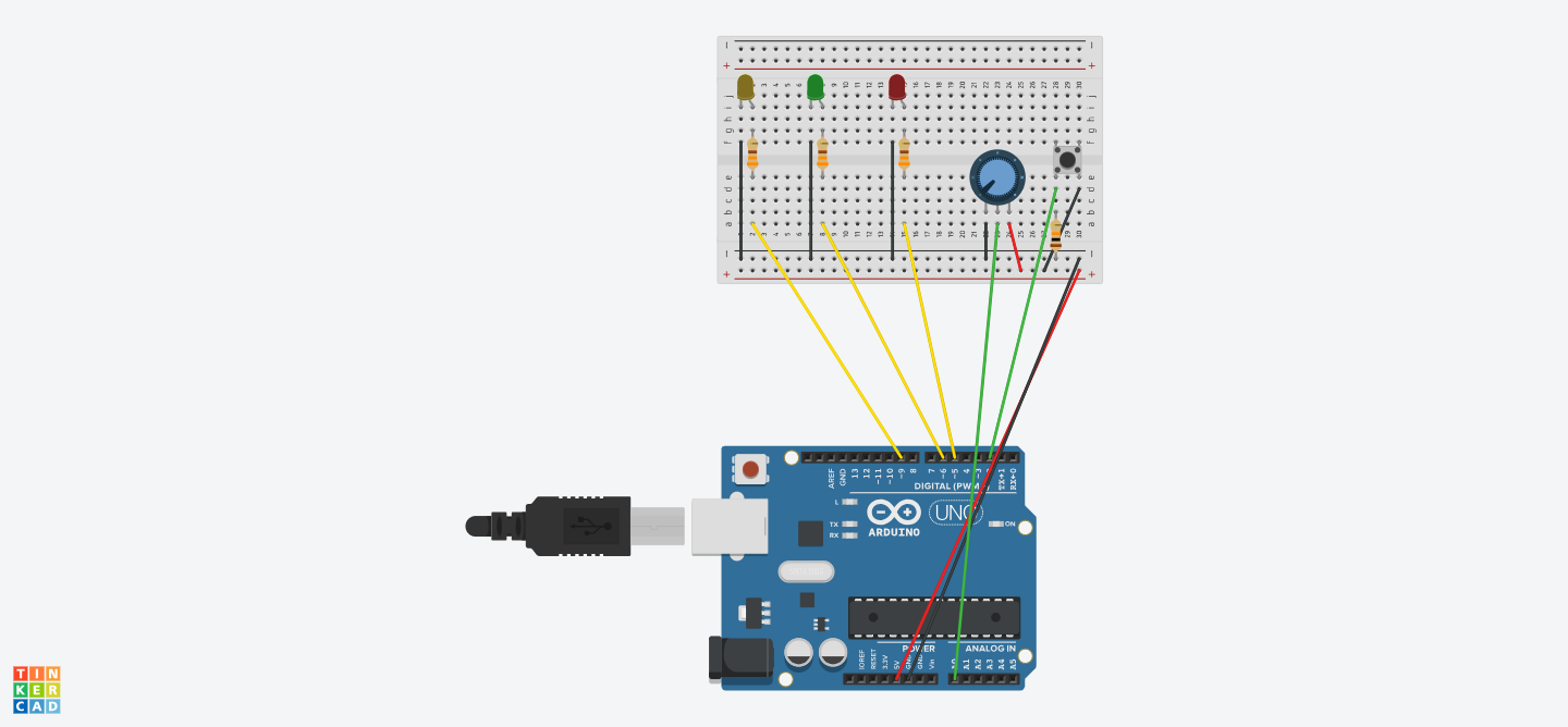
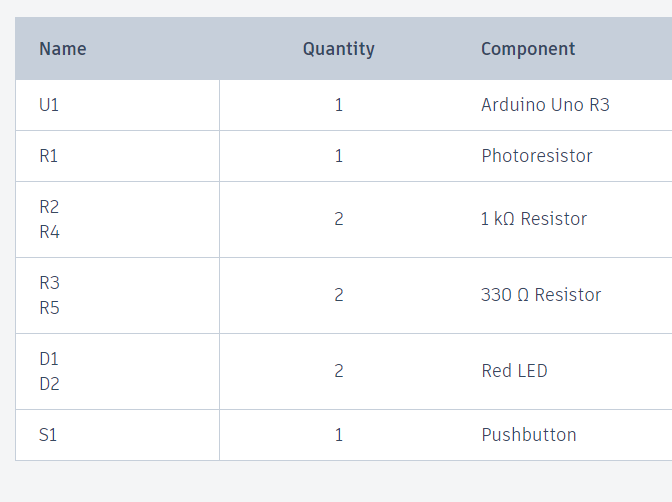
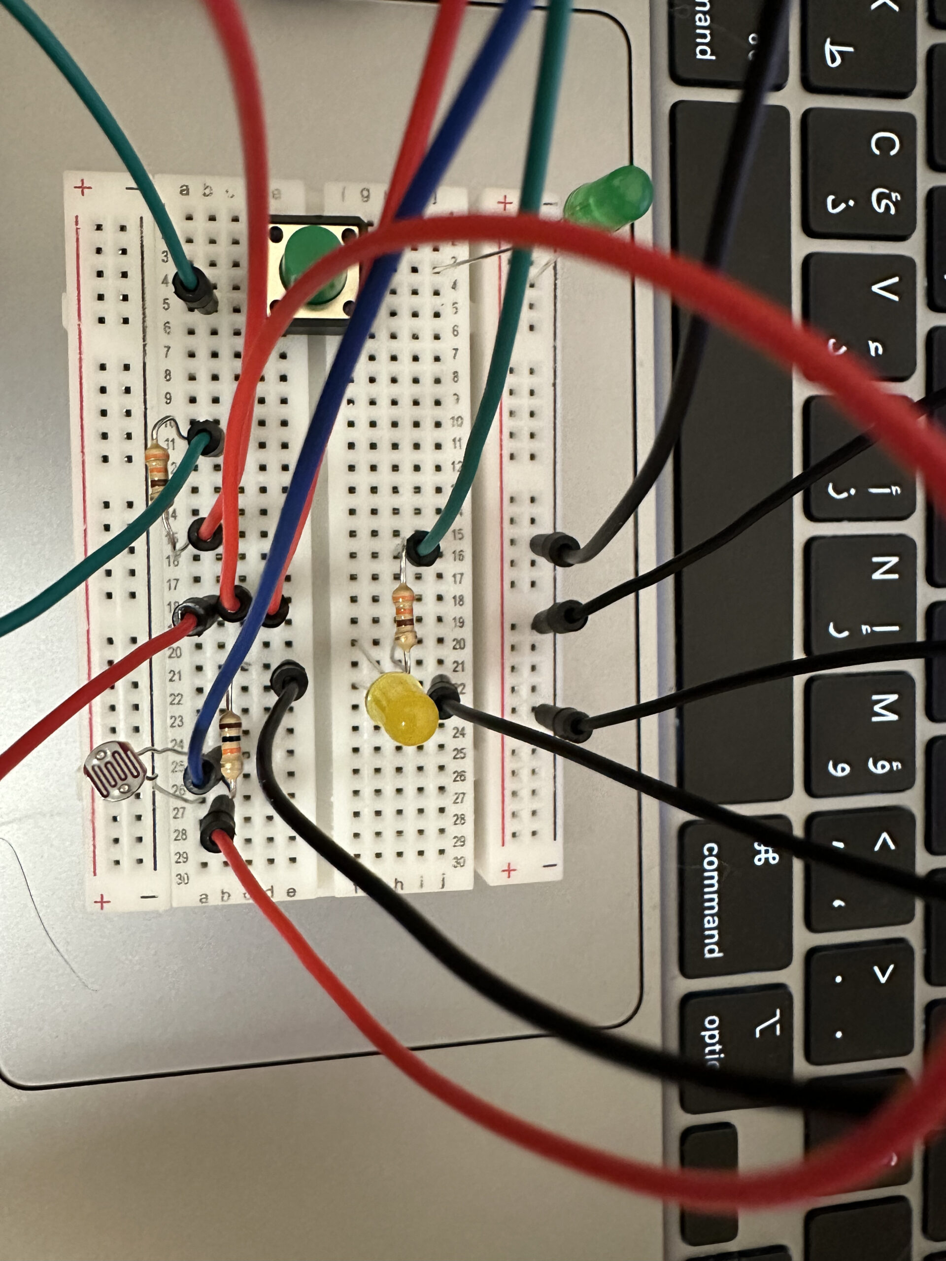
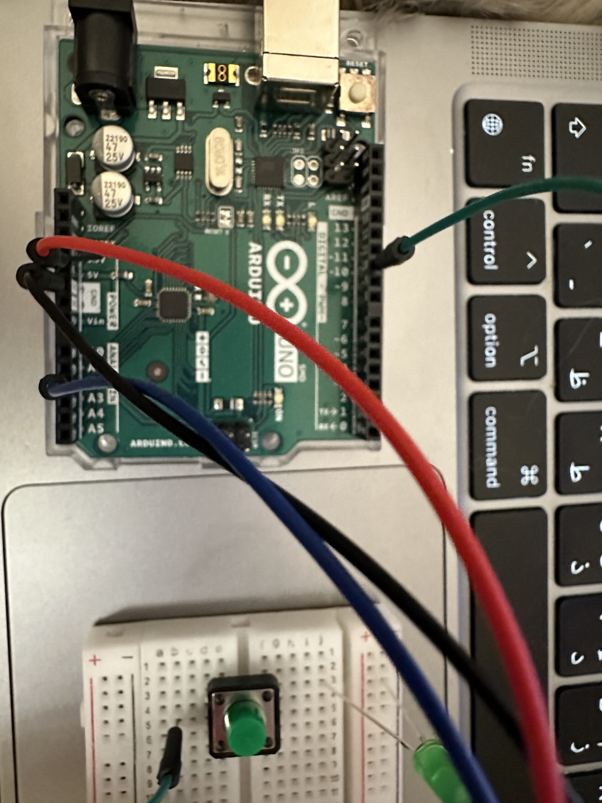
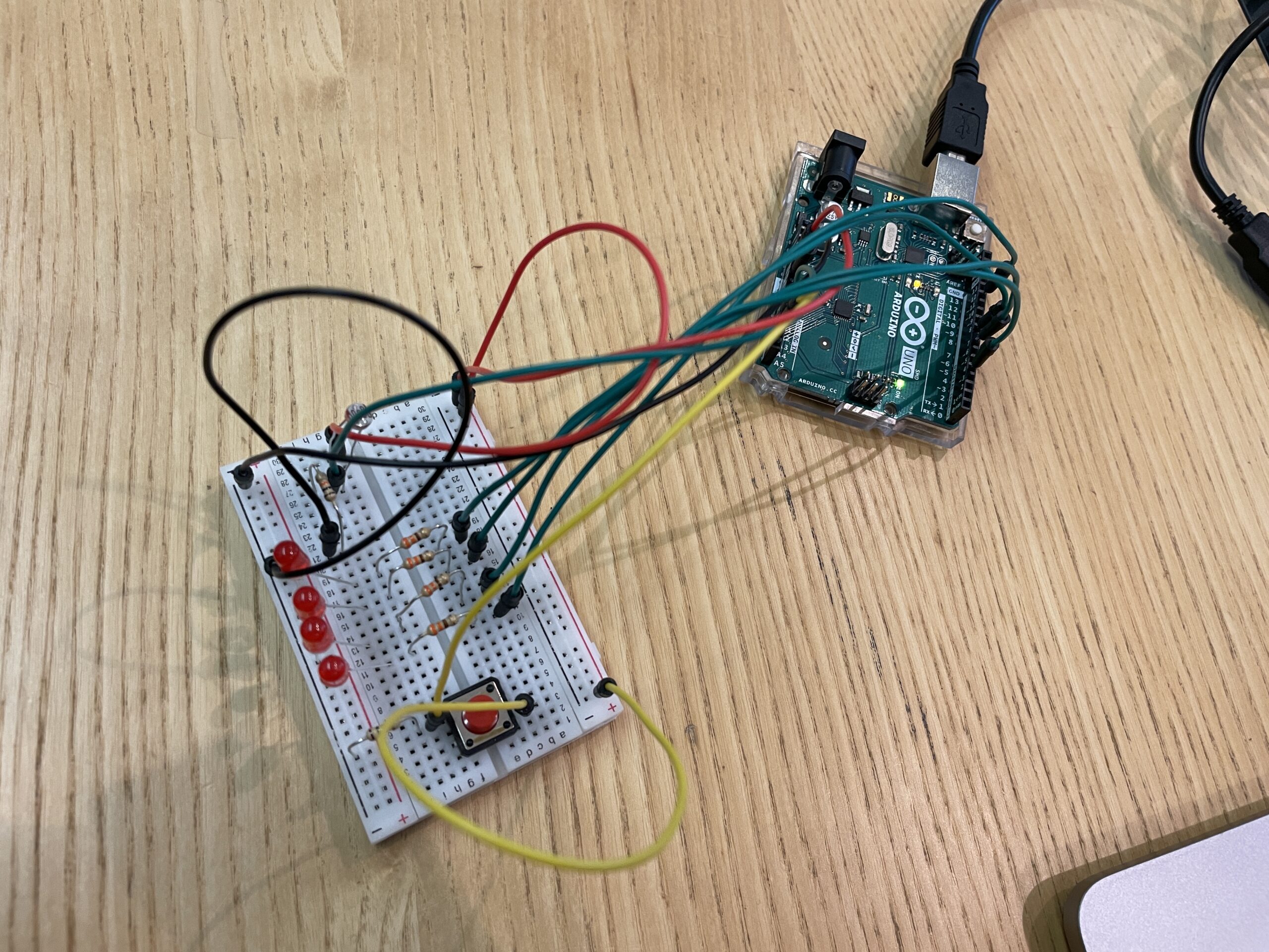
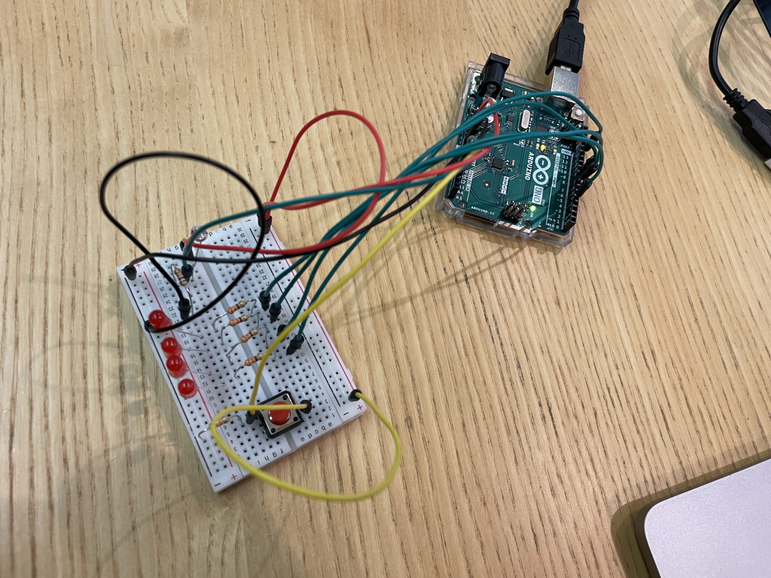
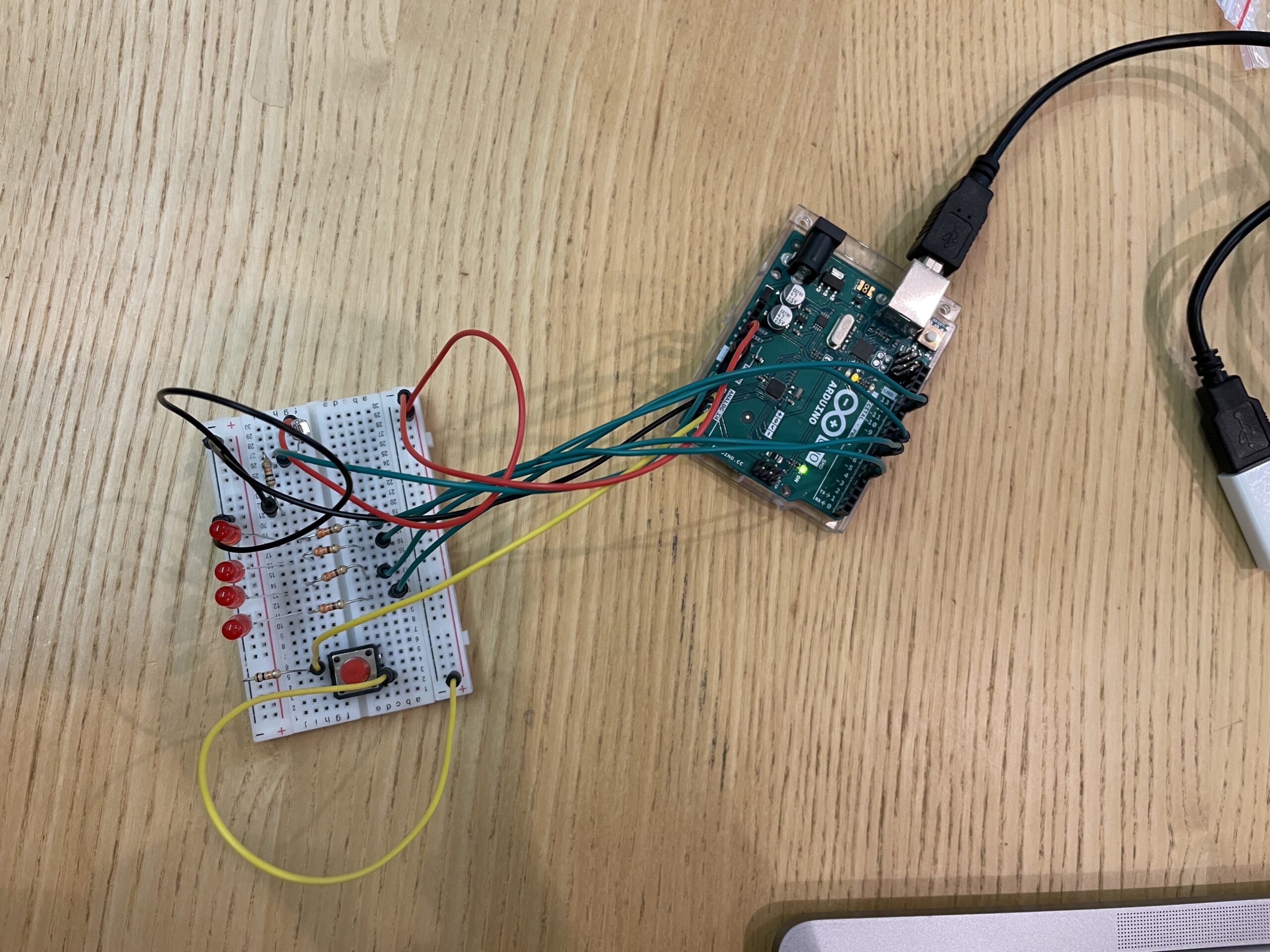
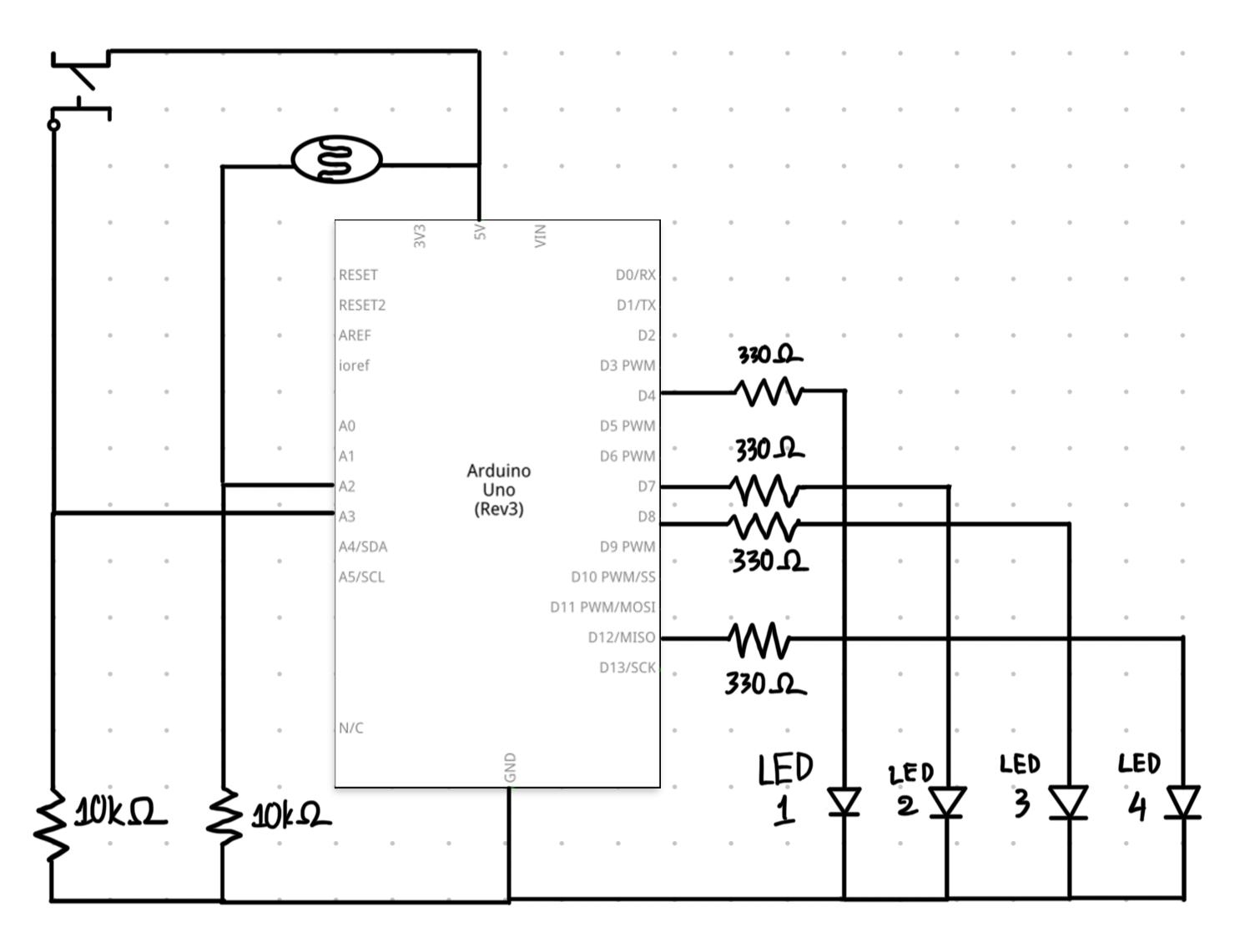
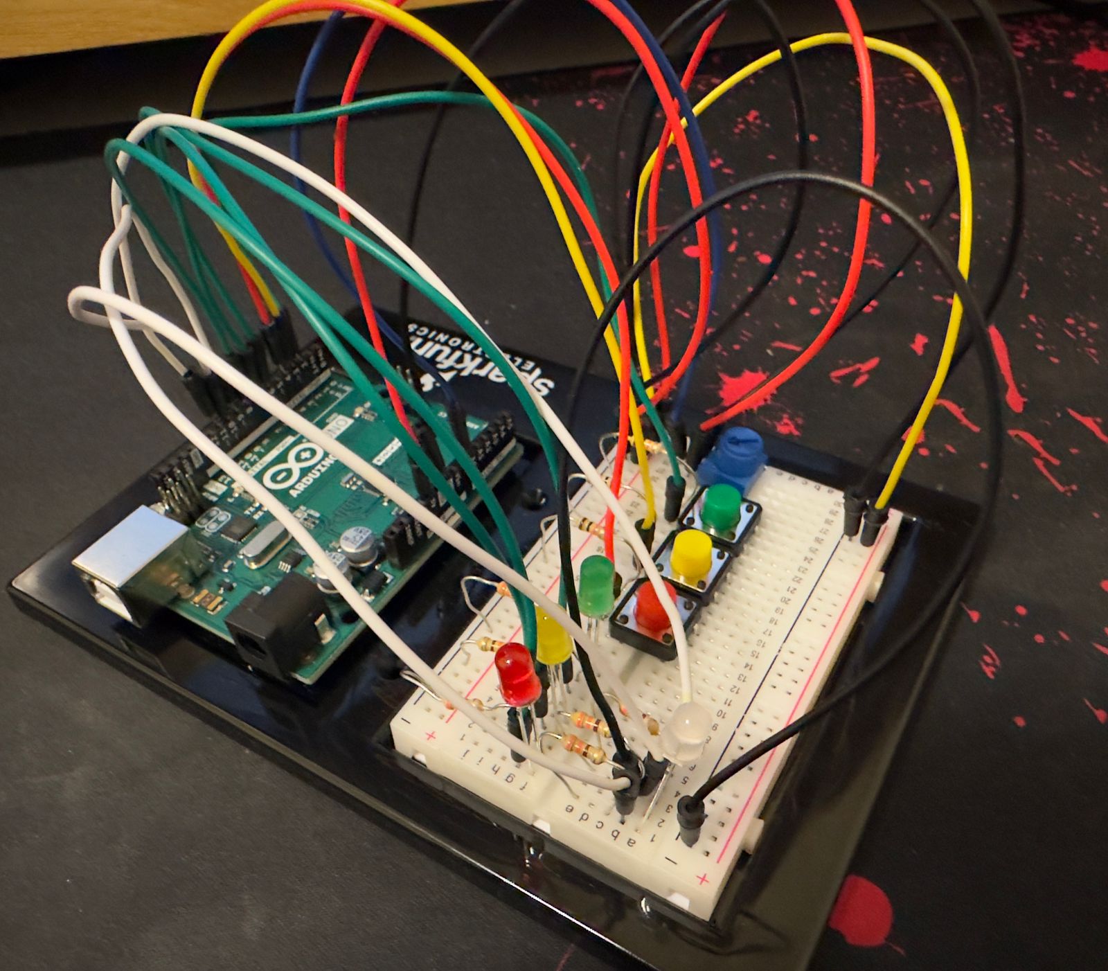
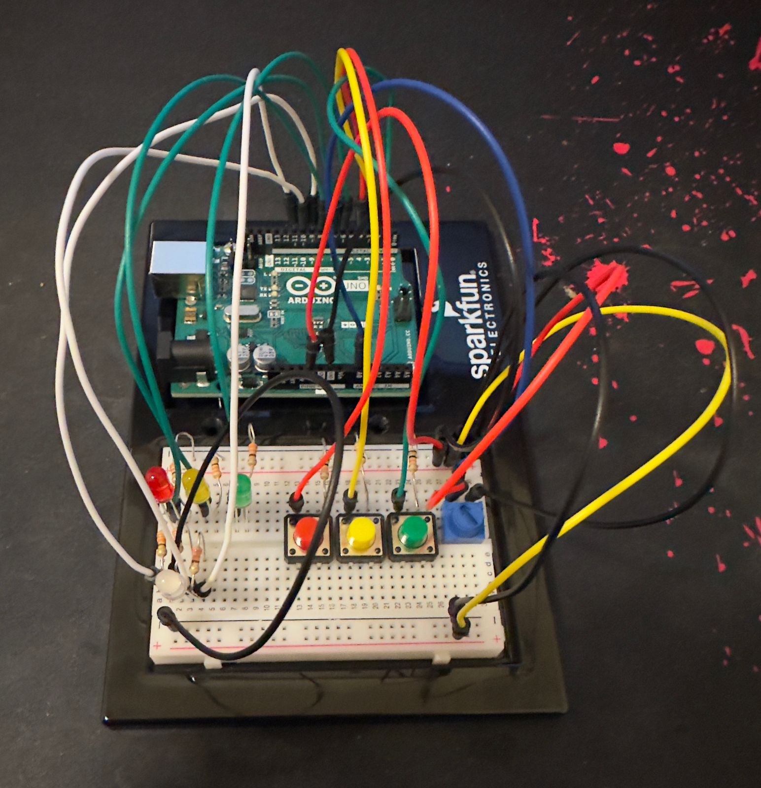
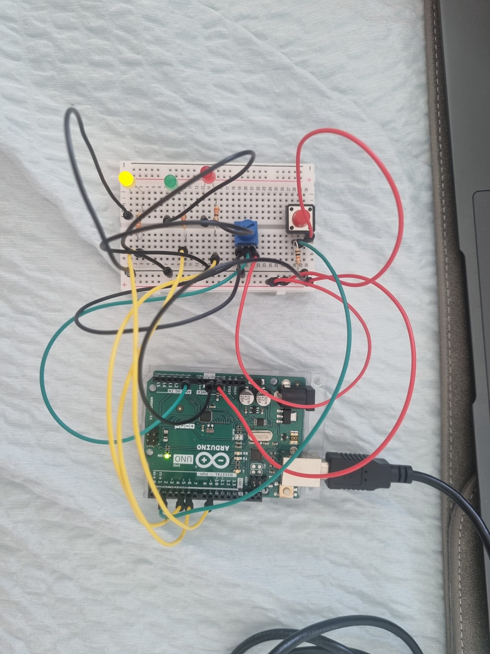
My circuit consists of the following elements:

– Arduino board (e.g., Arduino Uno)

– Potentiometer

– Push button switch

– LED

– Resistors

– Breadboard

– Jumper wires

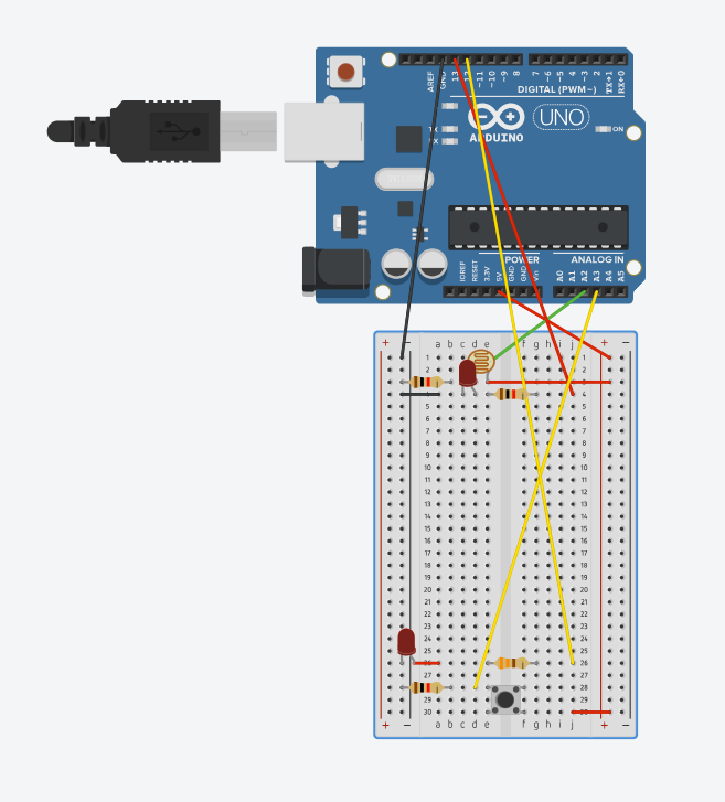
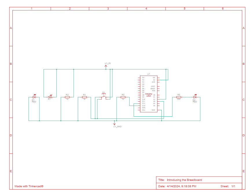
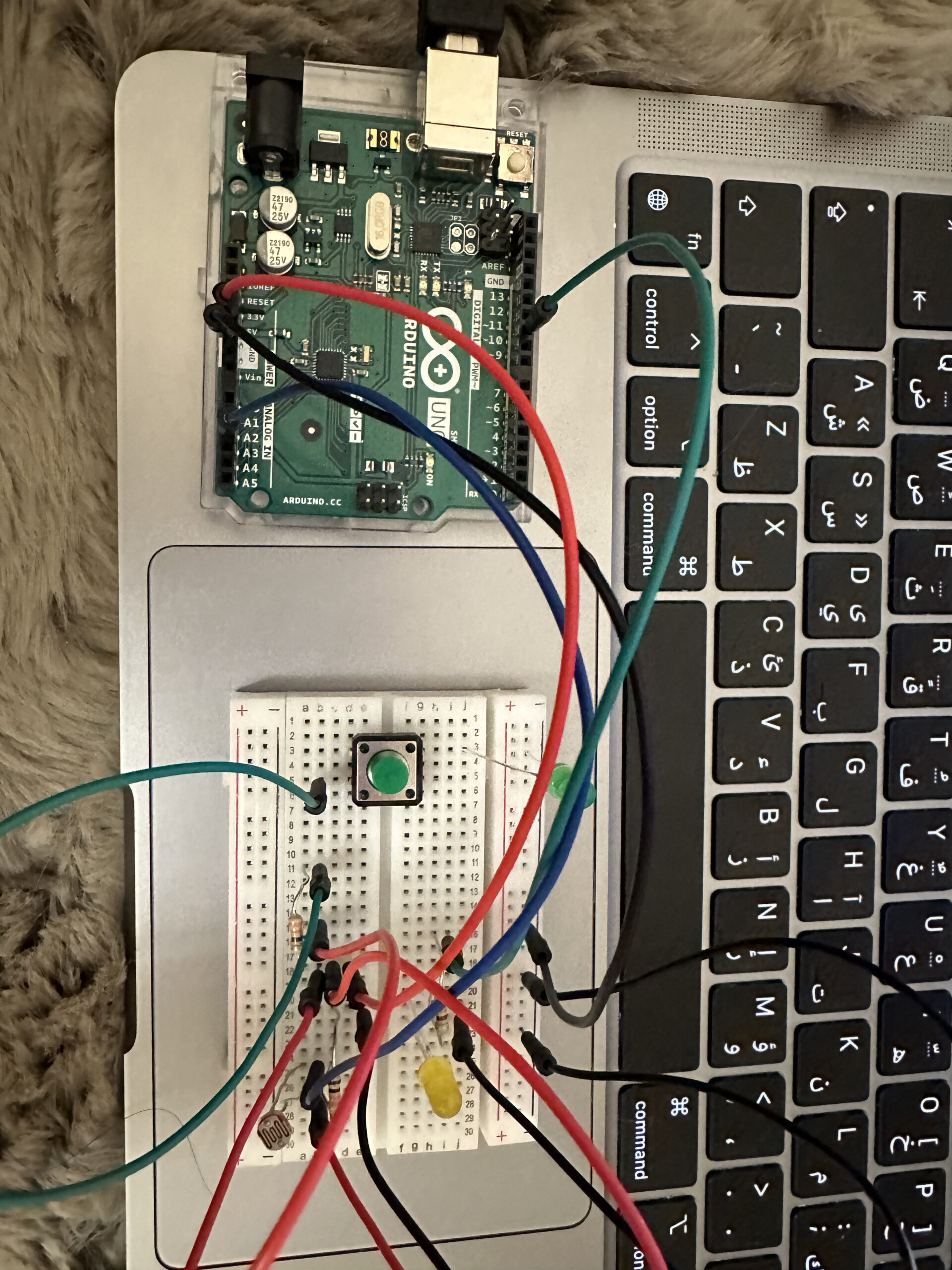
In this circuit, a potentiometer is connected to an analog input pin of the Arduino, allowing it to read varying voltage levels. A push button is connected to a digital input pin, enabling the Arduino to detect button presses. Three digital output pins are connected to the red, green, and yellow pins of the LED, respectively. By adjusting the potentiometer, users control the brightness of the LED colors, while pressing the button cycles through the available colors.

Code

// Pins
const int POTENTIOMETER_PIN = A0; // Analog input pin for potentiometer
const int BUTTON_PIN = 2; // Digital input pin for push button
const int RED = 5;  // Digital output pin for RGB LED (red)
const int GREEN = 6;  // Digital output pin for RGB LED (green)
const int YELLOW = 9; // Digital output pin for RGB LED (yellow)

// Variables
int potentiometerValue = 0; // Potentiometer value
bool buttonState = false; // Button state
int colorIndex = 0; // Index of current color

void setup() {
  pinMode(POTENTIOMETER_PIN, INPUT);
  pinMode(BUTTON_PIN, INPUT_PULLUP);
  pinMode(RED, OUTPUT);
  pinMode(GREEN, OUTPUT);
  pinMode(YELLOW, OUTPUT);
}

void loop() {
  potentiometerValue = analogRead(POTENTIOMETER_PIN);
  
  // Map potentiometer value to LED brightness
  int brightness = map(potentiometerValue, 0, 1023, 0, 255);
  
  // Set the LED color based on the current color index
  switch (colorIndex) {
    case 0:  // Red
      analogWrite(RED, brightness);
      analogWrite(GREEN, 0);
      analogWrite(YELLOW, 0);
      break;
    case 1:  // Green
      analogWrite(RED, 0);
      analogWrite(GREEN, brightness);
      analogWrite(YELLOW, 0);
      break;
    case 2:  // Yellow
      analogWrite(RED, 0);
      analogWrite(GREEN, 0);
      analogWrite(YELLOW, brightness);
      break;
  }

  // Check button state
  if (digitalRead(BUTTON_PIN) == LOW) {
    if (!buttonState) {
      // Toggle color index
      colorIndex = (colorIndex + 1) % 3;
      buttonState = true;
      delay(200);
    }
  } else {
    buttonState = false;
  }
}

This is my code. The analogRead function reads the value from the potentiometer, which is then mapped to control the brightness of the LED colors. The switch statement selects the appropriate color based on the current color index, and the digitalWrite function sets the brightness of the corresponding LED pins accordingly. When the button is pressed, the color index is incremented to cycle through the available colors.

Improvements and Overview

Overall, I enjoyed this assignment, particularly the aspect of controlling outputs using different physical inputs. The most challenging part was figuring out how the current moved through the circuit. However, I was able to easily determine the correct way to connect all the components. As a further improvement, I considered expanding the color palette by using a full RGB LED instead of individual colors. This would allow for a wider range of colors and more creative possibilities.

Luke Nguyen – Week 10 Reading

I was particularly fascinated by the Gloves section in the Physical Computing’s Greatest Hits reading. It is interesting to learn how engineers created the gloves that could respond to the movements of fingers to make rhythm; I wondered how they created and programmed the force-sensing resistors so that when attached to the fingertips, these sensors would know what kinds of triggers to create according to how strong the forces are. A few years ago, I was amazed at how Ariana Grande could control music with her gloves during her Honeymoon Tour in 2015. Here are a few videos of the way she did it: video 1, video 2. After doing some research, I discovered that she was using the Mi.Mu Gloves developed by MI.MU GLOVES LIMITED (UK) which enables music through movement as the company advertised. During her tour, Ariana used the motions and forces of her gloved hand gestures to add effects to her live performances, for example: holding up one finger to add harmony, opening her palm to add major-sounding harmonies, etc. I didn’t know back then that this technology is called physical computing; it was physical computing that enabled her to do this. In retrospect, it is amazing how physical computing has opened up countless opportunities for musicians to create and control their music both in studio and live environment. This glove technology is a mega hit to them.

I resonate with the author’s point in the second article “Making Interactive Art: Set the Stage, Then Shut Up and Listen”. I think artists’ intentions while making the interactive artworks are important but the audience’s experience is equally important as well. Most of the time when I see an interactive artwork, it is interactive in itself but not to the spectators, which I find to be rather frustrating. One time when I was visiting the Museum of Natural Science, there was a very awesome exhibition about nature that I remembered till this day. The exhibition was showcased in a sphere. When visitors stepped inside, they would directly interact with the elements of nature through their feet. One would step on the elements, for example, water, leaves, wind, bubbles, butterflies, etc. to see how they would become interactive. I got no instructions on how to interpret the artwork but I learned how to interact with it purely through interacting with it. I felt alive; I felt that was such a unique experience; the artwork made me want to play with it again and again. In contrast, most of the interactive artworks I had seen before this one were presumably “interactive” but I wasn’t given any opportunity to interact with them. I did not know how to feel viscerally towards what I was observing, which I think made the objects hardly memorable without photography after moving on from them.

Week 10 – Everything, Everywhere, All at Once

Concept

I wanted to explore how different components can interact with each other in a circuit. It is not simply how the buttons can control the lights or the variable resistors can transmit ranges of analog values. I want to understand if I can make an indirect interaction between the lights and the resistors such that I can light up another light using a light.

IMPLEMENTATION

Using a button, I manipulate 1 light to light up as we push down on the button. For the analog input, I used the photocell to manipulate another light to light up when I am not covering it. However, another special thing is that the button can also control the second light when the photocell is covered.

Below is an estimation of the material that I used:


Below is the schematic for circuit:

Code implementation:

int led1 = 13;
int led2 = 12;
int brightness = 0;

// the setup routine runs once when you press reset:
void setup() {
  // initialize serial communication at 9600 bits per second:
  Serial.begin(9600);
  pinMode(led1, OUTPUT);
  pinMode(A3, INPUT);
  pinMode(led2, OUTPUT);
}

// the loop routine runs over and over again forever:
void loop() {
  // read the input on analog pin 0:
  int sensorValue = analogRead(A2);
  int buttonState = digitalRead(A3);

  sensorValue = constrain(sensorValue, 500, 900);
  brightness = map(sensorValue, 500, 860, 255, 0);

  analogWrite(led1, brightness);
  analogWrite(led2, brightness);

  Serial.println(sensorValue);
  delay(30);  // delay in between reads for stability


  if (buttonState == LOW){
    digitalWrite(led2, LOW);
  }
  else{
    digitalWrite(led2, HIGH);
  }
}

Video in Action

I realized that everything in my circuit is connected to each other even though there is no link between them. Take the inspiration of the movie “Everything, Everywhere, All at Once”, the ultimate result can only happen if all of the previous actions are done:

Challenges

It is quite difficult to grasp the concept of using different small circuits to serve for the bigger general circuit. I have a bit of trouble to utilize the brightness of another LED to adjust the value for the photocell. However, it works out in the end as I try to figure out the correct range of the new values of the photocell with the LED.

Reflection

Even though I was able to make a schematic diagram for the circuit, it is quite unorganized right now, I would like to learn more about how I can organize the wires and components so that it can be seen clearly in the diagram.

Week 10: Digital and Analog

Concept:

The idea of this assignment is to have differently controlled LED lights. In this example, they act as lights outside of an airplane bathroom. When the bathroom is occupied, the yellow light is either on or off (digital) . When it is unoccupied, the green LED senses that there is no light in the room and therefore turns on the green light gradually (analog). This can also be used in a parking lot which depicts whether a parking is available or not.

Watch here:

IMG_4713

IMG_4713

For the analog pin, I used pin 10, with A2 used for the input. I used both resistors for it, the 10K and 330 ohm ones. As for the digital pin, it only required the 330 ohm resistor.


Code:

int led = 10;         // the PWM pin the LED is attached to
int brightness = 0;  // how bright the LED is

// the setup routine runs once when you press reset:
void setup() {
  Serial.begin(9600);
  // declare pin 10 to be an output:
  pinMode(led, OUTPUT);
}

// the loop routine runs over and over again forever:
void loop() {
  int sensorValue = analogRead(A2);

  sensorValue = constrain(sensorValue, 30, 210);

  analogWrite(led, sensorValue/4);

  brightness = map(sensorValue, 30, 210, 0, 255);

  Serial.println(sensorValue);

  // wait for 30 milliseconds to see the dimming effect
  delay(30);
}

Difficulties:

As I was working on it, I struggled so much with trying to get both LED lights to work at the same time as they both needed power from 5V. A few  LED lights were burnt while figuring that out. Eventually, I knew how to fix that by connecting two wires to the 5V wires then connecting those to each input (button and photoresistor).

Luke Nguyen – Week 10 Assignment – Thanos Snap


Concept & Inspiration:

I thought of Thanos in Marvel Comics while I listened to a song by Beyoncé where he is referenced. Analog versus sensor seems to be a duality that reminds me of the notion of half and half that Thanos is fervent believer of. He believes that if he wipes out half of the population of the universe, he could restore its balance (half-populated and half-empty); fully populated would tip the scale. This assignment is set in that universe. I want the population of the universe to be represented by the number of LEDs; I used 4 LEDs in this case. I would play 2 roles as I operate the circuit: the creator of life and Thanos. To bring “life” to the LEDs, I would use the photocell as the analog sensor. To destroy “life” inside the LEDs, I would use the button as the digital sensor.

Circuit:

Code:

When I touch the photocell (the analog sensor), I would bring “life” to the LEDs by making them turn on. When I press the button (the digital sensor), I would wipe out half of the universe (half of the number of lives) by turning off two pre-determined LEDs. This way, I only have to code in a way so that that is possible.

int led1 = 4;
int led2 = 7;
int led3 = 8;
int led4 = 12;
int brightness = 0;

// the setup routine runs once when you press reset:
void setup() {
  // initialize serial communication at 9600 bits per second:
  Serial.begin(9600);
  pinMode(led1, OUTPUT);
  pinMode(A3, INPUT);
  pinMode(led2, OUTPUT);
  pinMode(led3, OUTPUT);
  pinMode(led4, OUTPUT);
}

// the loop routine runs over and over again forever:
void loop() {
  // read the input on analog pin 0:
  int sensorValue = analogRead(A2);
  int buttonState = digitalRead(A3);

  sensorValue = constrain(sensorValue, 500, 900);
  brightness = map(sensorValue, 500, 860, 255, 0);


  if (brightness > 0){
    analogWrite(led1, brightness);
    analogWrite(led2, brightness);
    analogWrite(led3, brightness);
    analogWrite(led4, brightness);

    if (buttonState == HIGH ){
      digitalWrite(led3, LOW);
      digitalWrite(led4, LOW);
    }

  }

  Serial.println(sensorValue);
  delay(30);  // delay in between reads for stability

}

Challenges and reflections:

My biggest challenge has to do with the coding. I couldn’t figure out how to write the code for both the third and fourth LED, both of which are controlled by the analog sensor and the digital sensor at the same time, in a way that would make them turn on when I touched the photocell and turn off when I pressed the button.

A first few attempts resulted in these 2 LEDs not turning on at all, them only turning on when I was not touching the photocell, them turning on when I touched the photocell but not turning off when I pressed the button.

The commented-out parts are these first few attempts:

void loop() {
  // read the input on analog pin 0:
  int sensorValue = analogRead(A2);
  int buttonState = digitalRead(A3);

  sensorValue = constrain(sensorValue, 500, 900);
  brightness = map(sensorValue, 500, 860, 255, 0);

  // analogWrite(led1, brightness);
  // analogWrite(led2, brightness);
  // analogWrite(led3, brightness);
  // analogWrite(led4, brightness);


  // if (buttonState == LOW && sensorValue > 600 ){
  //   digitalWrite(led3, HIGH);
  //   digitalWrite(led4, HIGH);
  // }
  // else{
  //   digitalWrite(led3, LOW);
  //   digitalWrite(led4, LOW);
  // }


  if (brightness > 0){
    analogWrite(led1, brightness);
    analogWrite(led2, brightness);
    analogWrite(led3, brightness);
    analogWrite(led4, brightness);

    if (buttonState == HIGH ){
      digitalWrite(led3, LOW);
      digitalWrite(led4, LOW);
    }

  }
  // else{
  //   if (buttonState == LOW ){
  //     digitalWrite(led3, HIGH);
  //     digitalWrite(led4, HIGH);
  //   }
  //   else{
  //     digitalWrite(led3, LOW);
  //     digitalWrite(led4, LOW);
  //   }
  // }

  Serial.println(sensorValue);
  delay(30);  // delay in between reads for stability

}


Week 10 Reading Response: From Physical computing to Shut up and Listen!

This weeks readings were very interesting, not only because they served as a great inspiration for my final project but at the same time made me think more deeply about my designs and projects.

Starting of from the Physical Computing reading, I really resonated with the sentence that says that everything is already done and we can not just imagine or make something new. Those type of moments happen very often, where you think that whatever you want to invent has already been made and there is no point in copying it but we can always add a personal twist. Let’s look at some examples:

  • Pi’s midterm game: Has a game ever been played on an Instrument: Yes. Has a game ever been made with p5.js: A ton of them. Was Pi’s midterm projects something unique and fascinating: TOTALLY! By adding some personal elements and experiences Pi actually made a great game which he controlled by a guitar which is a huge part of his personality.
  • Interactive dolls and pets are mentioned, and I couldn’t stop thinking about the project from Thecla Schiphorst called Soft(n). More info bellow:https://www.sfu.ca/~tschipho/softn/index.html. The thing about this projects is so unique and it only comes from a simple concept: You hug one pillow, and another pillow gets that information and gives the feeling of being hugged to a different user.

As we can see, creativity has no limits and we can all mix match and invent something interesting as well as add a personal element to it.

As for the second reading, we are once again getting back to simple and most important PROPER Design. As the reading says, if an artist needs to talk for hours and hours explaining and introducing the users on how to use or interact with his exhibition, then he has not done a good job. A very well designed exhibition should be obvious to the users  but at the same time add a level of discoverability so that the user can feel more “in-touch” or resonate with it. That is why we as artists or creators have an obligation to really think about how our users or viewers will interact with our creations and really make the process as smooth and fun as possible.

Week 10: Ultrasonic Sensors and LEDs

Concept

For this weeks assignment I wanted to create a parking space detector system that assists drivers in finding available parking spots quickly and efficiently. It utilizes an ultrasonic sensor to detect the presence of vehicles in front of designated parking spaces. Through a series of LEDs, the system provides visual feedback to indicate the availability of parking spots to approaching drivers.

Technical Details:

I have used the ultrasonic sensor, after looking into it – this sensor emits ultrasonic waves and measures the time it takes for the waves to bounce back after hitting an object. Which means that it can be used to determines the distance of the object from its position.

LED Indicators

Connected the anode (longer leg) of each LED to digital pins 8, 9, and 10 on the microcontroller respectively.

Connected the cathode (shorter leg) of each LED to ground through a resistor ( 220Ω to 330Ω) to limit current and prevent damage.

Green LED: Indicates a vacant parking space. When the distance measured by the ultrasonic sensor exceeds a certain threshold (indicating no object is present), the green LED lights up, signaling to approaching drivers that the parking spot is available for use.

  • Red LED: Represents a partially occupied parking space. If the distance measured falls within a predefined range, suggesting the presence of a vehicle but with some space remaining, the red LED illuminates. This warns drivers that the space is partially occupied and may not be suitable for parking larger vehicles.
  • Blue LED: Signals a fully occupied or obstructed parking space. When the measured distance is very close to the sensor, indicating a fully occupied space or an obstruction such as a wall or pillar, the blue LED turns on. This prompts drivers to avoid attempting to park in the space to prevent potential collisions or damage to vehicles.
  • Ultrasonic Sensor:
    • Trig Pin: Connected  to digital pin 2 on the microcontroller.
    • Echo Pin: Connected to digital pin 3 on the microcontroller.
    • Vcc: Connected to 5V.
    • GND: Connected to ground.
  • Button:
    • One side connects to digital pin 13 on the microcontroller.
    • The other side connects to ground.
Code
// Define LED pins
int ledPin[3] = {8, 9, 10};

// Define Ultrasonic sensor pins
const int trigPin = 2; // or any other unused digital pin
const int echoPin = 3; // or any other unused digital pin

const int buttonPin = 13;
int buttonState = HIGH;
int lastButtonState = HIGH;
long lastDebounceTime = 0;
long debounceDelay = 50;
int pushCounter = 0;
int numberOfLED = 3;

void setup() {
  pinMode(buttonPin, INPUT);
  digitalWrite(buttonPin, HIGH); // Activate internal pull-up resistor
  
  // Set up LED pins
  for (int i = 0; i < numberOfLED; i++) {
    pinMode(ledPin[i], OUTPUT);
  }
  
  // Set up Ultrasonic sensor pins
  pinMode(trigPin, OUTPUT); // Sets the trigPin as an OUTPUT
  pinMode(echoPin, INPUT);  // Sets the echoPin as an INPUT
}

void loop() {
  int reading = digitalRead(buttonPin);

  // Check if the button state has changed
  if (reading != lastButtonState) {
    // Reset the debounce timer
    lastDebounceTime = millis();
  }

  // Check if the debounce delay has passed
  if ((millis() - lastDebounceTime) > debounceDelay) {
    // If the button state has changed, update the button state
    if (reading != buttonState) {
      buttonState = reading;

      // If the button state is LOW (pressed), increment pushCounter
      if (buttonState == LOW) {
        pushCounter++;
      }
    }
  }

  // Update the last button state
  lastButtonState = reading;

  // Turn off all LEDs
  for (int i = 0; i < numberOfLED; i++) {
    digitalWrite(ledPin[i], LOW);
  }

  // Perform Ultrasonic sensor reading
  long duration, distance;
  digitalWrite(trigPin, LOW);
  delayMicroseconds(2);
  digitalWrite(trigPin, HIGH);
  delayMicroseconds(10);
  digitalWrite(trigPin, LOW);
  duration = pulseIn(echoPin, HIGH);
  distance = (duration * 0.0343) / 2; // Calculate distance in cm

  // Perform actions based on distance measured
  if (distance < 10) {
    // Turn on first LED
    digitalWrite(ledPin[0], HIGH);
  } else if (distance < 20) {
    // Turn on second LED
    digitalWrite(ledPin[1], HIGH);
  } else if (distance < 30) {
    // Turn on third LED
    digitalWrite(ledPin[2], HIGH);
  }

  // Delay before next iteration
  delay(100); // Adjust as needed
}
Circuit

Video of the Final Circuit

Reference

I watched this video to get familiar to the ultrasonic sensor.

Week 10: Glow Rush Game

Concept

This week, I set out to blend analog and digital elements into a single creative project, leading me to design a reaction game inspired by the “reaction lights” game by Lummic I stumbled upon a few months ago. In this game, players test their reflexes by pressing a button as soon as its corresponding light turns on.

I integrated a tricolor RGB light that serves as a real-time indicator of the player’s reaction time—green signals excellent speed, blue is moderate, and red denotes a slower response. To add a twist and enhance engagement, I included a potentiometer to adjust the game’s difficulty, effectively changing the time intervals that define the three color responses. This setup not only challenges players but also gives them control over the complexity of the task, making each round adaptable and uniquely challenging.

Images


Components Used

  1. Arduino Uno
  2. Tricolor RGB LED
  3. Pushbuttons (3)
  4. Resistors:
    1. 330 ohm resistors (3)
    2. 10k ohm resistors (3)
  5. Potentiometer
  6. Breadboard
  7. Jumper Wires

Circuit Setup

  1. RGB LED
    • The common cathode of the RGB LED connects to the Arduino’s ground.
      The red, green, and blue anodes are connected to PWM-capable digital pins (9, 10, and 11) through 330-ohm resistors to limit current.
  2. Pushbuttons
    • Each button is connected to one of the digital input pins (2, 3, and 4).
      The other side of each button is linked to the ground through a 10k-ohm resistor to ensure the pin reads LOW when the button is unpressed.
  3. Potentiometer
    • One outer pin connects to the 5V on the Arduino, and the other to the ground. The middle wiper pin is connected to analog input A0, allowing the Arduino to read varying voltage levels as the potentiometer is adjusted.

Video

Code

void setup() {
  for (int i = 0; i < 3; i++) {
    pinMode(buttonPins[i], INPUT_PULLUP);
    pinMode(ledPins[i], OUTPUT);
  }

  // Set up RGB LED pins as outputs
  pinMode(redPin, OUTPUT);
  pinMode(greenPin, OUTPUT);
  pinMode(bluePin, OUTPUT);

  Serial.begin(9600);
}


Input pins (buttonPins): Configured with INPUT_PULLUP to use the internal pull-up resistors, ideal for buttons.
Output pins (ledPins and RGB LED pins): Set as outputs to control LEDs.

void loop() {
  int potValue = analogRead(potPin); 
  // Adjust the max delay range for more sensitivity
  int maxDelay = map(potValue, 0, 1023, 5000, 2000); 
  Serial.print("Potentiometer Value: ");
  Serial.print(potValue);
  Serial.print(", Max Delay (ms): ");
  Serial.println(maxDelay);

  if (!gameActive) {
    gameActive = true;
    targetLed = random(0, 3);
    digitalWrite(ledPins[targetLed], HIGH);
    startTime = millis();
    Serial.print("Game started, respond before ");
    Serial.print(maxDelay);
    Serial.println(" ms for the best score!");
  }

  if (digitalRead(buttonPins[targetLed]) == LOW) {
    // Debounce by ensuring at least 50 ms has passed
    if (millis() - startTime > 50) { 
      unsigned long reactionTime = millis() - startTime;
      Serial.print("Reaction Time: ");
      Serial.println(reactionTime);

      setColorFromReactionTime(reactionTime, maxDelay);
      // Show result for 1 second
      delay(1000); 
      // Turn off RGB LED
      setColor(0, 0, 0); 
      digitalWrite(ledPins[targetLed], LOW);
      gameActive = false;
      delay(1000); 
    }
  }
}

There are 3 main steps in the loop function:

  1. Read Potentiometer: Determines the difficulty level by reading the potPin and mapping its value to define maxDelay, the maximum time allowed for a response.
  2. Game Control
    1. If gameActive is false, the game starts by picking a random LED to light up and marks the start time.
    2. If the corresponding button is pressed (digitalRead(buttonPins[targetLed]) == LOW), it checks for debouncing (to ensure the button press is genuine) and then calculates the reaction time.
  3. Serial Output: Outputs debug information such as potentiometer value and maximum delay time to the serial monitor.
void setColorFromReactionTime(unsigned long reactionTime, int maxDelay) {
  // Set RGB LED color based on reaction time as a fraction of maxDelay
  if (reactionTime < maxDelay / 5) {
    // Fast: Green
    setColor(0, 255, 0); 
  } else if (reactionTime < maxDelay / 2) {
    // Moderate: Blue
    setColor(0, 0, 255); 
  } else {
    // Slow: Red
    setColor(255, 0, 0); 
  }
}

It is based on the player’s reaction time, this function sets the color of the RGB LED:

  • Fast Response: Less than 1/5 of maxDelay, the LED turns green.
  • Moderate Response: Less than 1/2 but more than 1/5 of maxDelay, it turns blue.
  • Slow Response: Slower than 1/2 of maxDelay, it turns red.

Week 10: Reading Response

The main focus of Tom Igoe’s perceptive essay is the change from the artist serving as the exclusive storyteller to acting as a facilitator. Artists have historically used their creations to directly communicate a message or an emotion. On the other hand, interactive art plays a transforming function, whereby the artwork acts as a catalyst for the audience’s discovery. I like this transition as this aligns with the tenets of user experience design, which emphasize empowering users to choose their paths rather than trying to control them.

In traditional art, viewers often interpret a piece based on the artist’s description and the experience they want to show their viewers. Interactive art, however, offers a different dynamic. Each interactive piece is a canvas for numerous personal narratives, evolving with every user interaction. Here, the artwork doesn’t present a fixed story; instead, it allows for a multitude of stories to emerge, each shaped by individual interactions. The artist sets the framework, but it’s the participants who create their unique narratives through their engagement with the piece.

This is evident in modern interactive installations like “Rain Room,” where the experience of walking through a rainstorm without getting wet engages visitors in a unique conversation with the elements. I feel that the development of virtual reality environments adheres to these same principles that Igoe is proving in his argument. VR creators set the stage for experiences, but it is ultimately the users, through their actions and decisions, who navigate and mold these virtual worlds.

The text even highlighted that the user must be given hints or basic information about the interactive art piece. However, this made me ponder how the balance between guiding the audience and allowing freedom shapes the outcome of interactive art. Can there be too much or too little of either?

Week 10 – Reading Response

“Physical Computing’s Greatest Hits (and Misses)”

The review of recurrent project themes in educational settings captures the fine line between redundancy and innovation. Igoe’s encouragement for students to breathe new life into old ideas resonates with me, as it emphasizes the importance of creativity and personal expression in learning which is something that I feel strongly about. Personally, I find the discussion about the longevity and adaptability of simple projects like the Theremin and video mirrors particularly engaging. These projects, while simple, serve as a testament to the foundational skills being taught and the creativity they can unlock. The idea that a simple gesture, like moving your hand over a sensor, can create music or alter images is both magical and empowering. The section on video mirrors struck a chord with me; it’s described as the “screen-savers of physical interaction,” which is both amusing and apt. It underlines how some projects may lean more towards aesthetic value than interaction depth, but still hold significant educational value in terms of the skills they teach and their ability to engage viewers.

Moreover, Igoe’s mention of projects that have become almost iconic within the community, like the Drum Gloves and Mechanical Pixels, highlights an interesting aspect of physical computing: its blend of technology and tangible, interactive art. This intersection is where I see a lot of personal and academic growth potential, bridging the gap between technical skills and artistic expression.

“Making Interactive Art: Set the Stage, Then Shut Up and Listen”

This article also resonates with me because it champions the idea that art is not just an artist’s expression but a dynamic interaction. The artist’s role shifts from being a narrator to a facilitator who sets up the environment and then steps back to let the audience interact and derive their own meanings. The author persuasively argues against the traditional view of art as a static expression, pointing out that interactive art should be more like a conversation or a performance that evolves. The analogy of the artist as a director who does not strictly dictate but rather guides actors (or participants, in this case) allows for a genuine, emergent experience. This perspective is enlightening as it underlines the shift from passive consumption to active engagement. I appreciate Igoe’s emphasis on the importance of simplicity and clarity in setting up interactive environments. The directive to “arrange the space” thoughtfully and to “remove anything extraneous” serves as a crucial guideline for creating an immersive and intuitive experience. This approach ensures that each participant’s interaction is meaningful and personal, rather than overshadowed by the artist’s own interpretations or expectations.

Moreover, the concept of listening to how people interact with the artwork—and the notion that these interactions might change over time—adds a layer of complexity to the creation and exhibition of interactive art. It suggests that the artwork is not complete upon its initial display but continues to evolve and resonate differently as people engage with it.