Potentiometer Switch

I came up with the idea of this assignment while playing around with the potentiometer. It has a wide range of values it can provide and I wanted to utilize the potential of its variability and precision.

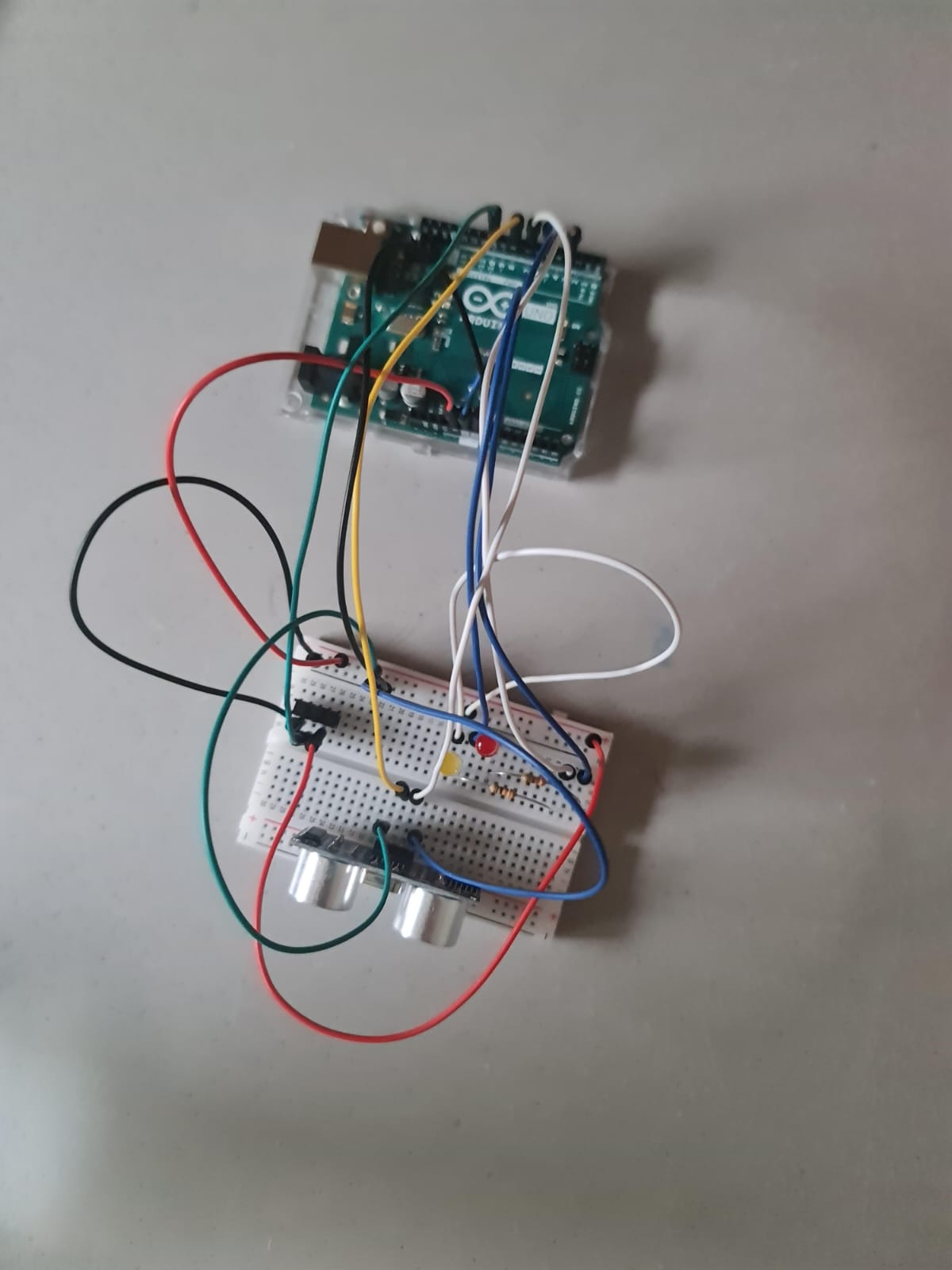
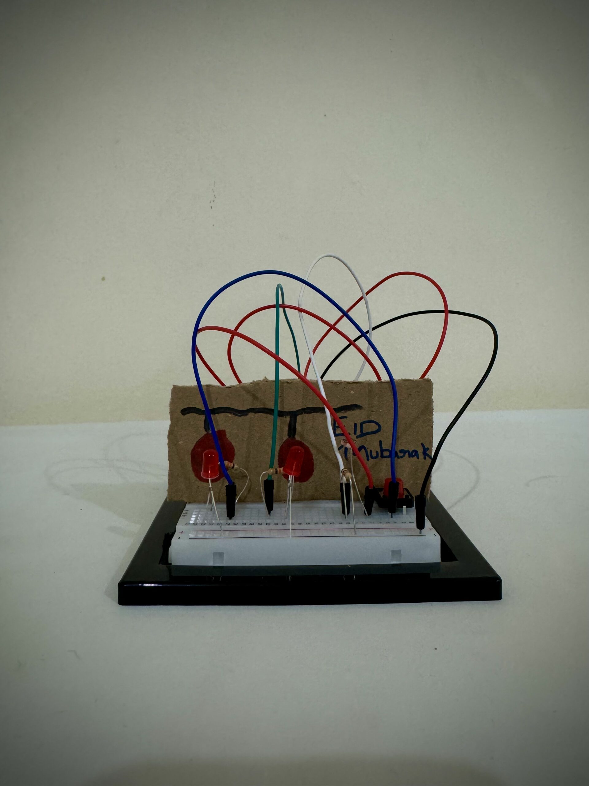
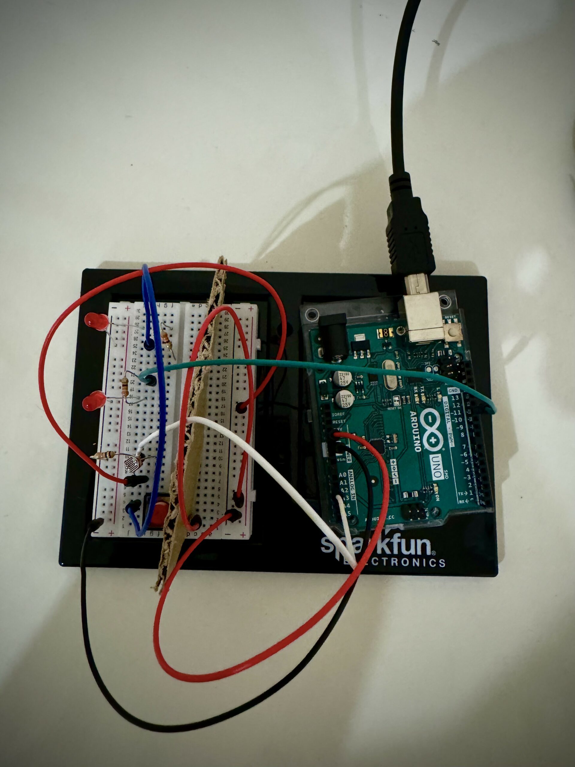
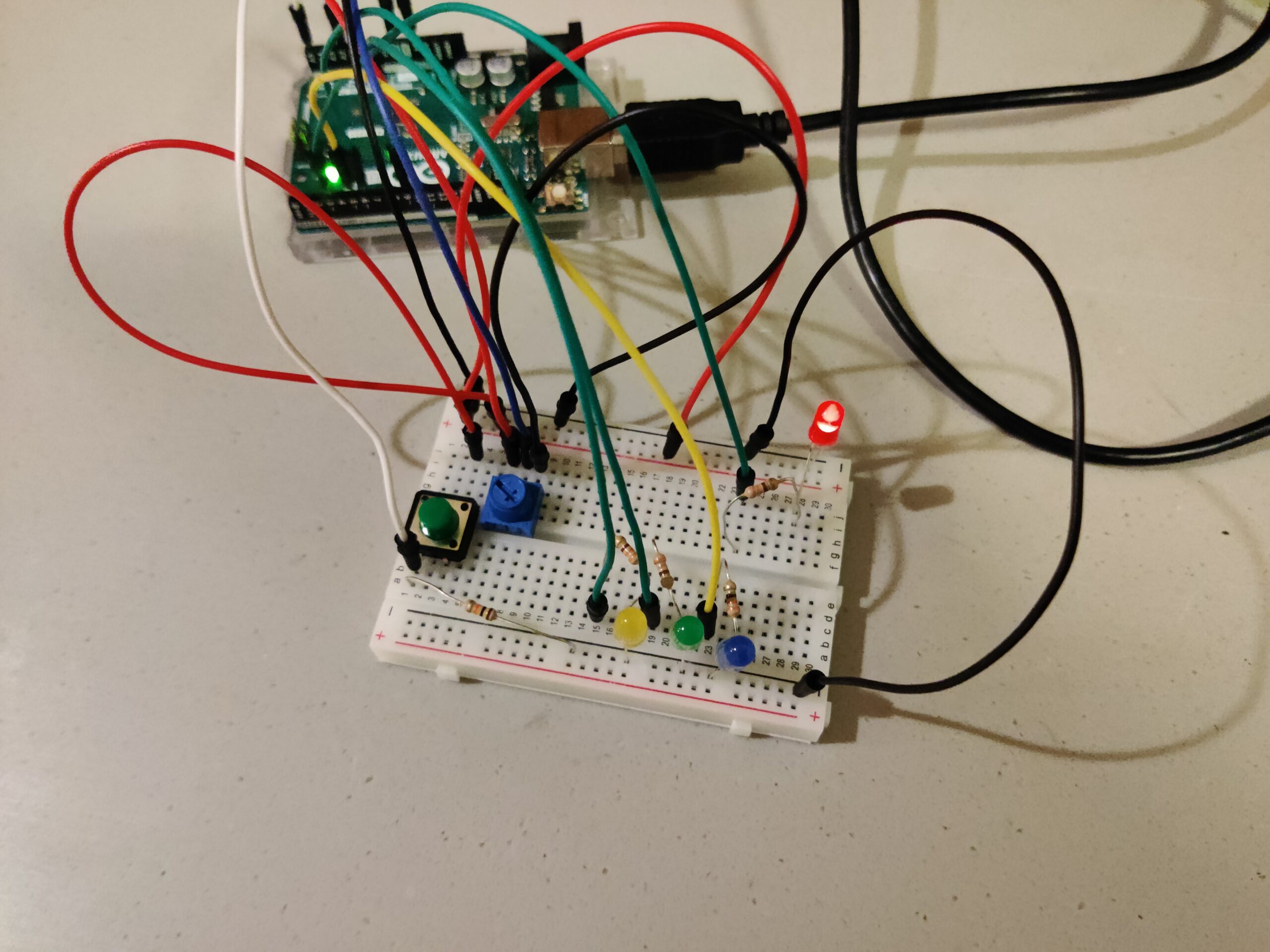
There are 4 LEDs – red, yellow, green and blue – that light up as the values generated by the variable resistor change. The potentiometer is the analog sensor here, but provides functionality of both an analog and a digital sensor. The purely digital sensor here is the green button.

The potentiometer values are supplied to the digital output pins and control the brightness of the LEDs. The value range of the potentiometer is also split into 4 equal segments, so that each LED only has a quarter of the full range of brightness it can take. The splitting also allows to switch the LED as the value changes, meaning for (0, 256] range of the potentiometer reading, one LED lights up with (0, 1/4] of its brightness range. Same logic applies to the other LEDs in a successive fashion.

The green button  (digital sensor) allows to change the sequence of LEDs that light up with certain values of the potentiometer. For instance, if initially the red LED has the lowest quarter of values, the switch sets that lowest range to the next LED in succession, which would be the yellow one, and every LED gets the position of the next one, hence in this example the red one would get the highest range of values and be the brightest if turned on. The video of how the system works is attached below.

The main code responsible for the button and the value switches is provided below. The relatively challenging part was figuring out a way to make the switch between what values which LED gets, and I ended up with an array structure for efficiency.

if (buttonState == HIGH){
    if (swapped == 0){
    switchState += 1;
    switchState = switchState % 4;
    }
    swapped = 1;
  }
  else{
    swapped = 0;
  }

  if (sensorValue > 0 && sensorValue <= 256){
    analogWrite(leds[switchState], sensorValue/4);
    digitalWrite(leds[(switchState+1)%4], LOW);
    digitalWrite(leds[(switchState+2)%4], LOW);
    digitalWrite(leds[(switchState+3)%4], LOW);
    //speed = 2000;
  }
  else if(sensorValue > 256 && sensorValue <= 512){
    digitalWrite(leds[switchState], LOW);
    analogWrite(leds[(switchState+1)%4], sensorValue/4);
    digitalWrite(leds[(switchState+2)%4], LOW);
    digitalWrite(leds[(switchState+3)%4], LOW);
    //speed = 1000;
  }
  else if(sensorValue > 512 && sensorValue <= 768){
    digitalWrite(leds[switchState], LOW);
    digitalWrite(leds[(switchState+1)%4], LOW);
    analogWrite(leds[(switchState+2)%4], sensorValue/4);
    digitalWrite(leds[(switchState+3)%4], LOW);
    //speed = 500;
  }
  else if(sensorValue > 768 && sensorValue <= 1023){
    digitalWrite(leds[switchState], LOW);
    digitalWrite(leds[(switchState+1)%4], LOW);
    digitalWrite(leds[(switchState+2)%4], LOW);
    analogWrite(leds[(switchState+3)%4], sensorValue/4);
    //speed = 250;
  }
  else{
    digitalWrite(red, LOW);
    digitalWrite(yellow, LOW);
    digitalWrite(green, LOW);
    digitalWrite(blue, LOW);
    //speed = 0;
  }

For improvements, I could add more variability into what the button does, possibly incorporate flickering rate for different potentiometer readings to make the transitions more clear. I also could optimize the code and make it more reusable so that when new functionality or LEDs are added, it does not take much code to incorporate.
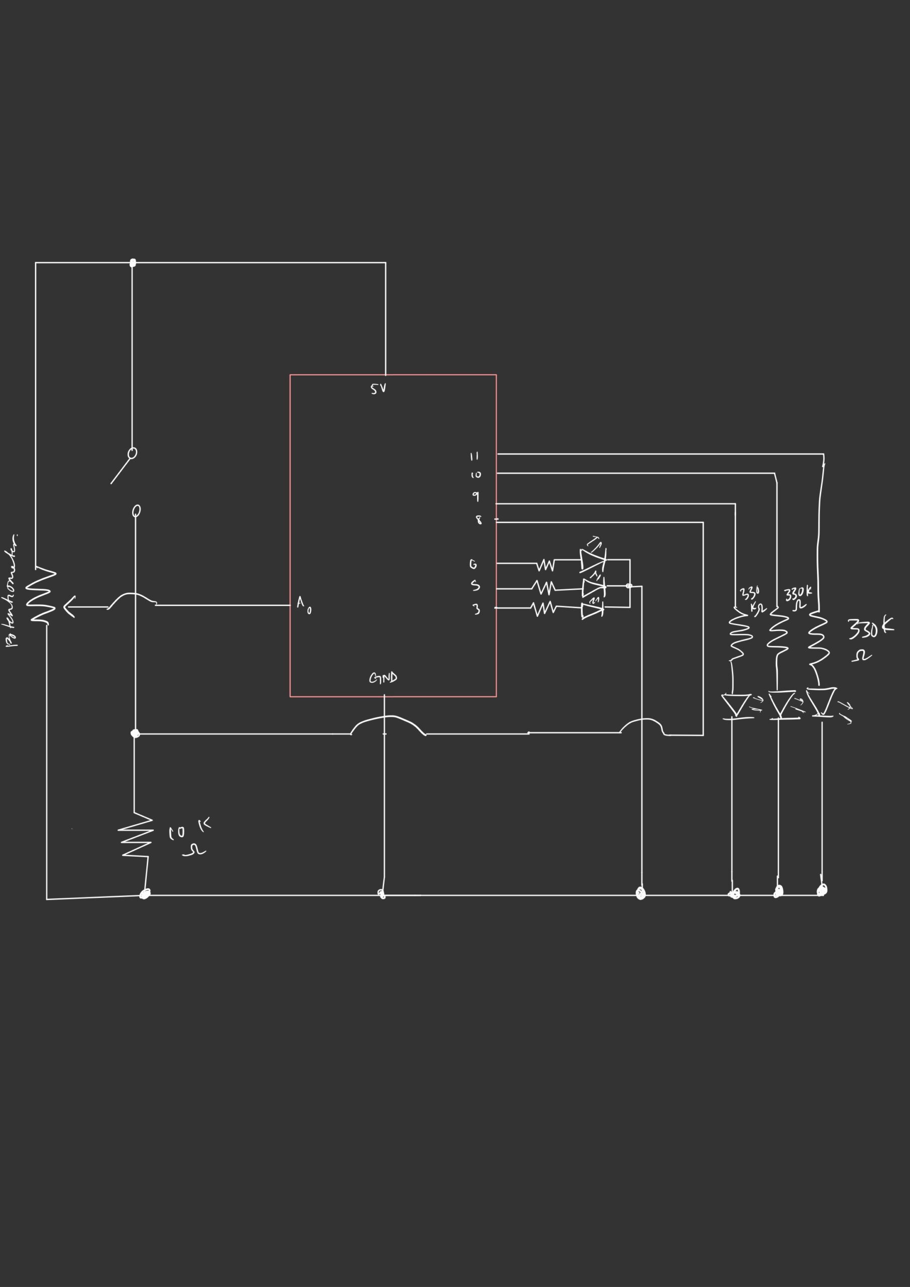
Week 10: Reading Response

First Article: Physical Computing’s Greatest Hits (and misses)

After reading this article, I find myself reflecting on its crucial aspects. The author discusses various themes in physical computing and highlights recurring project ideas. One point raised is the versatility of these themes, allowing for originality despite their frequent use. I can see evidence of this in the examples provided, such as the theremin-like instruments and gloves used for musical interaction. However, I wonder if the author’s enthusiasm for these themes might overshadow potential limitations or drawbacks. While the projects are indeed versatile and popular, are there certain constraints or challenges that aren’t fully addressed? Additionally, the emphasis on creativity and variation might suggest a bias towards celebrating the potential of physical computing without thoroughly examining its limitations or pitfalls.

Reading this has not drastically changed my beliefs, but it has prompted me to consider the balance between creativity and practicality in project development. Are there instances where prioritizing creativity might hinder the functionality or effectiveness of a physical computing project Furthermore, the discussion of themes like “Remote Hugs” and “Meditation Helpers” raises questions about the effectiveness of technology in facilitating emotional experiences. Can machines truly simulate or enhance human connection and emotional well-being, or do they risk oversimplifying complex human experiences?

Overall, I think while the reading offers valuable insights into the world of physical computing, sententiously it also prompts critical thinking about the intersection of technology and human interaction.

Second Article: Making Interactive Art: Set the Stage, Then Shut Up and Listen

After reading this article, I find the author’s perspective on interactive art thought-provoking. They emphasize the importance of not interpreting one’s own work in the context of interactive art. Instead, the author suggests setting the stage for interaction and then allowing the audience to interpret and respond to the artwork in their own way. I agree with the notion that providing interpretation alongside interactive art can limit the viewer’s experience by dictating how they should perceive and engage with the piece. By allowing space for individual interpretation, the artwork becomes a platform for dialogue between the artist and the audience.

The comparison made between planning interactive artwork and directing actors resonates with me. Just as a director guides actors without imposing specific interpretations, an artist should create opportunities for interaction without prescribing meaning. This approach allows for more authentic and varied responses from the audience. However, I wonder about the balance between providing context for interaction and leaving room for interpretation. How can an artist effectively guide the audience’s engagement without imposing their own biases or intentions?

Furthermore, the idea of interactive artwork as a performance highlights the dynamic nature of the audience’s role in completing the work. How can artists create environments or stimuli that encourage meaningful interaction and exploration without overshadowing the audience’s agency?Overall, I feel the article challenges traditional notions of authorship and interpretation in art, encouraging a more open and collaborative approach to creating interactive experiences.

Physical Computing and Making Interactive Art Reading Response – Redha

Both of this week’s readings led me to consider interactive art’s relationship with previously understood notions of human interaction and the production of art.

The reading on physical computing led me to identify two forms of approaching human-centred interactive design. The first of which is the repurposing and reapplication of interactions that already exist in the ‘real world’. The two examples that caught my eye which fall under this category were the ‘drum gloves’ and ‘video mirrors’. To me, the latter elevates the universal, almost reflex-like desire to look at oneself in the mirror and creates space for a quite direct form of symbolism (i.e “seeing x in yourself”). The former effectively borrows ‘gestural language’ from the ‘real world’ act of tapping one’s hands to make a beat. Again, this is an example of a familiar act being elevated but introduces an element of learning which is not present in video mirrors. I feel that this point introduces a spectrum of effort required by the user to uphold their side of the ‘conversation’ upon which interactive designs must place themselves. In this case, if video mirrors are like conversation with a talkative person, drum gloves aer like trying to connect with an introvert (i.e it is possible, it’ll just take some time).

Conversely, the reading on making interactive art provided me with a new perspective on its place within the larger artistic space. Previously, I would attempt to receive interactive art in the same way that I would receive other forms of contemporary art. The point raised by the reading that the role of an interactive artist is not to present a complete narrative but to best prepare the user to experience the narrative provided an interesting perspective which I have accepted. With this in mind, it is not unfair to double-down on the notion that interactive art is not complete without the input of the user. Rather than present a complete story, the role of the interactive artist is to facilitate a conversation between the art itself and the user which, hopefully, leads to a meaningful interaction at the end.

Week 10 | Proximity-activated LEDs

Concept

For this week’s assignment , we were required to take an analog and a digital input from two sensors to control two LEDs . I decided to use a slide switch for the digital input and the ultrasonic sensor for the analog input (distance of an object from the sensor). The slide switch is used to switch between the two LEDs that are of different colors . The ultrasonics sensor is used to detect the distance of an object from it. As an object gets closer and closer, the LED gets brighter and brighter. This could be  as some kind of an alert switch that grows bright when an object gets closed to it . It could be used for automatic proximity lighting or in security systems.

Schematics

I used tinkerCAD to simulate my project and generate the schematics below:

Schematic Diagram

View on TinkerCAD


List of Components


Code

I am using a library called newPing that handles input from the sensor HC-SR04 (ultrasonic distance sensor). The code is given below:

#include <NewPing.h> // Include the NewPing library

//Created by Aadil Chasmawala

const int LEDPin1 = 3; // Define LEDPin1 as a constant integer
const int LEDPin2 = 5; // Define LEDPin2 as a constant integer
const int switch_PIN= 10; //switch PIN
int brightness1;
int brightness2;
NewPing Mysensor(8, 7, 200); // Trigger pin = 8, echo pin = 7, max_distance = 200cm

void setup() {
  pinMode(LEDPin1, OUTPUT); // Set LEDPin1 pin mode to output
  pinMode(LEDPin2, OUTPUT); // Set LEDPin2 pin mode to output
  pinMode(switch_PIN,INPUT); 
  Serial.begin(9600); // Initialize serial communication
}

void loop() {
  int distance = Mysensor.ping_cm(); // Get the distance in centimeters
  Serial.println(distance); // Print the distance to the serial monitor
  if(distance > 50){ //if distance is more than 50 , switch the LED off
    brightness1=0;
    brightness2=0;
  }
  else{
  // Map the distance to the brightness of the LEDs
  brightness1 = map(distance, 0, 50, 255,0); // Adjust the range as needed
  brightness2 = map(distance, 0, 50, 255,0); // Adjust the range as needed
  }

  // Set the brightness of the LEDs
  bool state = digitalRead(switch_PIN);
  Serial.println(state);

  if(state == HIGH){ // if switch is in one state (towards 5V)
  analogWrite(LEDPin1, brightness1);
  analogWrite(LEDPin2,0);
  }
  else if (state == LOW){ //if the slide switch is towards ground
  analogWrite(LEDPin2, brightness2);
   analogWrite(LEDPin1,0);
  }

  delay(100); // Wait for a short time before taking another measurement
}


Video Demonstration/ Images

Link to the video- https://youtu.be/Unpllzq1EK8

Challenges and Reflections

I had some issues in using push buttons for the digital input as there would be a noticeable delay between when the button was released and the detection of that release. However, this was resolved by using a slide switch instead of a button switch.

Since I am using a library called <newPING.h>, I don’t have to worry about sending and receiving pulses from the trigger and echo pins respectively. The ping_cm handles it . At some point, the sensor was not working as expected so I printed the value of distance in the serial monitor for debugging and was able to resolve the issue.

Overall, I am happy with the way the brightness of LED changes with the distance and the quick switching of LED using a slide switch. For future projects, I hope to continue experimenting with different inputs and use them in creative ways.

Week 10: Reading Response

Physical Computing’s Greatest Hits (and misses)

This reading allowed me to think of physical computing in a different approach. When coming up with ideas for a project, I usually take so much time to think of something that has never been done before. After looking at these works, they are merely inspired by other artists’ works, in which they may have similar themes in terms of interaction but also convey completely different messages and ideas. The works shown inspired me to think of my own iteration of these themes and ideas.

Making Interactive Art: Set the Stage, Then Shut Up and Listen

While reading this, it reminded me of a previous reading we had, The Design of Everyday Things by Don Norman. Norman thinks that a design of something should communicate how it is going to be used. Similarly, this reading also tells us about how our artwork doesn’t have to give out instructions to others. We should allow our audience to interpret it themselves and receive feedback from them to adjust our work accordingly.

Week 10: Analog/Digital – Guess Who’s Murderer (Pi)

Let’s look at what I need to do…

(Post documentation on blog): Get information from at least one analog sensor and at least one digital sensor (switch), and use this information to control at least two LEDs, one in a digital fashion and the other in an analog fashion, in some creative way.

Hmm… so I can do something along the lines of

  • Ultrasonic Sensor (Analog)
  • Switch (is a requirement)
  • 4 LEDs (3 controlled by digitalWrite, and one fade In/Out through analog PWM)

In some creative way?? Hmm, how about we turn the entire project into a detective game, where you have to guess the murderer by pointing at one of the 3 suspects, then Arduino will tell you whether you got it right or wrong.

Guess Who’s Murderer

Hence, my project…

The player step into the shoes of a cunning detective, whose aim is to unravel the identity of the true culprit among the Crimson Enigma, the Emerald Marksman, and the Honey Hitwoman.

Using their hand, the player must point to one of the suspects. An ultrasonic sensor, detects the location of the player’s hand, illuminating the corresponding LED to indicate their suspicion.

To make their guess official, the player presses a pushbutton. If the guess is correct, a green LED softly fades in and out. However, if the player points their accusatory finger at the wrong suspect, the game’s buzzer sounds.

The demo video is below.

Art

All artworks are generated with midjourney… and some photoshop thrown in.

CODE

The code is below. Note that I am implementing a entire thing as a state machine, where the game alternates between the

{ SELECT_MURDERER, GUESS, CORRECT_GUESS, WRONG_GUESS }

states. This makes the code clean. The microcontroller randomly selects the murderer using a random number generation algorithm, which is triggered at the start of each new game loop.

// Pin Definitions
const int buttonPin = 12;   // Pushbutton pin
const int buzzerPin = 7;    // Buzzer pin
const int greenLedPin = 44; // Green LED pin
const int redLedPins[] = {3, 6, 10}; // Red LEDs for murderer selection
const int trigPin = 2;      // Ultrasonic sensor trigger pin
const int echoPin = 4;      // Ultrasonic sensor echo pin

// Game state definitions
enum GameState { SELECT_MURDERER, GUESS, CORRECT_GUESS, WRONG_GUESS };
GameState currentState;

// Variables for game logic
int murderer = 0;
int guess = -1;
int buttonState = 0;
int lastButtonState = LOW;
unsigned long previousMillis = 0; // for non-blocking delays

void setup() {
  Serial.begin(9600);
  pinMode(buttonPin, INPUT);
  pinMode(buzzerPin, OUTPUT);
  pinMode(greenLedPin, OUTPUT);
  for (int i = 0; i < 3; i++) {
    pinMode(redLedPins[i], OUTPUT);
  }
  pinMode(trigPin, OUTPUT);
  pinMode(echoPin, INPUT);
  randomSeed(analogRead(0));
  currentState = SELECT_MURDERER;
}

void loop() {
  switch (currentState) {
    case SELECT_MURDERER:
      selectMurderer();
      break;
    case GUESS:
      manageGuess();
      break;
    case CORRECT_GUESS:
      handleCorrectGuess();
      break;
    case WRONG_GUESS:
      handleWrongGuess();
      break;
  }
}

void selectMurderer() {
  murderer = random(0, 3); // Randomly select a murderer among 3 LEDs
  Serial.print("Murderer is: LED ");
  Serial.println(murderer);
  currentState = GUESS;
}

void manageGuess() {
  lightRedLEDsBasedOnDistance();
  readButtonState();
  if (buttonState == HIGH && lastButtonState == LOW) {
    Serial.println("Button Pressed");
    checkGuess();
  } else if (buttonState == LOW && lastButtonState == HIGH) {
    Serial.println("Button Released");
  }
  lastButtonState = buttonState;
}

void lightRedLEDsBasedOnDistance() {
  long distance = measureDistance();
  Serial.print("Distance: ");
  Serial.print(distance);
  Serial.println(" cm");
  for (int i = 0; i < 3; i++) {
    digitalWrite(redLedPins[i], LOW);
  }
  if (distance >= 2 && distance < 6) {
    digitalWrite(redLedPins[0], HIGH);
    guess = 0;
  } else if (distance >= 6 && distance < 9) {
    digitalWrite(redLedPins[1], HIGH);
    guess = 1;
  } else if (distance >= 9 && distance <= 12) {
    digitalWrite(redLedPins[2], HIGH);
    guess = 2;
  }
}

void readButtonState() {
  buttonState = digitalRead(buttonPin);
}

void checkGuess() {
  if (guess == murderer) {
    currentState = CORRECT_GUESS;
  } else {
    currentState = WRONG_GUESS;
  }
}

void handleCorrectGuess() {
  fadeGreenLED();  // Handles the fading of the LED over 4 seconds
  currentState = SELECT_MURDERER;
}

void handleWrongGuess() {
  buzzBuzzer(3);   // Buzzes the buzzer 3 times
  currentState = SELECT_MURDERER;
}

void fadeGreenLED() {
  for (int i = 0; i <= 255; i += 5) {
    analogWrite(greenLedPin, i);
    delay(30);
  }
  for (int i = 255; i >= 0; i -= 5) {
    analogWrite(greenLedPin, i);
    delay(30);
  }
}

void buzzBuzzer(int count) {
  for (int i = 0; i < count; i++) {
    digitalWrite(buzzerPin, HIGH);
    delay(300);
    digitalWrite(buzzerPin, LOW);
    delay(300);
  }
}

long measureDistance() {
  digitalWrite(trigPin, LOW);
  delayMicroseconds(2);
  digitalWrite(trigPin, HIGH);
  delayMicroseconds(10);
  digitalWrite(trigPin, LOW);
  long duration = pulseIn(echoPin, HIGH);
  return duration * 0.034 / 2;  // Calculate distance in cm
}

Week 10 – Reading Reflection – It’s not the artist performance

In the reading “Making Interactive Art: Set the Stage, Then Shut Up and Listen”, I understand that the creators are not the main performance. Interactive art allows users to impose actions onto the artworks instead of only observing. Therefore, their user experience and their understandings are different from each other with the same interactivity of the artwork.

Hence, we need to guide the users to the experience that we want them to have. As it is mentioned in the reading, we can give hints, use the space, use the design to allow the users to understand their respective actions. However, after that, it is the users’ performance. It will become their experience and their understandings because arts do not necessarily have a set meaning that we need the others to understand.

Finally, there are a variety of physical computing arts. Even though it may be in the same category, it does not mean that the users will have the same experience. For example, there are multiple projects about music. However, each project may require different skillset and understanding in music to interact with. Therefore, it is important to always experiment with the any project without the fear to be repetitive.

Week 10 Reading Response – Jihad Jammal

Jihad Jammal

Intro to IM

Professor Aaron Sherwood

Reading Reflection Week 10

April. 15, 2024


Re-evaluating Creativity


Tom Igoe’s perspectives on physical computing and interactive art present a compelling reevaluation of how creativity is often framed, particularly the expectation of producing entirely novel works. He argues persuasively for the value of revisiting and reinterpreting existing themes, thus challenging the traditional pursuit of absolute novelty in both art and technology. This approach strikes me as both practical and liberating, suggesting that innovation can flow from iteration—a continuous dialogue with established ideas—rather than emerging ex nihilo. This notion that revisiting familiar concepts can be a rich soil for personal expression and originality really resonates with me, encouraging a more inclusive and sustainable model of creative practice.


Building on Igoe’s redefined approach to creativity, his analogy of interactive art to a stage set for audience participation further deepens the dialogue about the creator-audience relationship. This model, which advocates for minimal intervention by the artist after the artwork’s initial presentation, challenges traditional notions of artistic control and opens up new possibilities for viewer engagement. Personally, I find this perspective transformative; it shifts the completion of an artwork’s meaning to the realm of audience interaction, thereby changing how art is consumed and interpreted. This democratization not only makes art more accessible but also enhances its depth by welcoming a multitude of interpretations.


Citations:

www.tigoe.com. (n.d.). Physical Computing’s Greatest Hits (and misses) – hello. [online] Available at: https://www.tigoe.com/blog/category/physicalcomputing/176/.


Anon, (n.d.). Making Interactive Art: Set the Stage, Then Shut Up and Listen – hello. [online] Available at: https://www.tigoe.com/blog/category/physicalcomputing/405/.

Week 10 – EID Decoration

Concept

For this assignment, the task is to get information from at least one analog sensor and at least one digital sensor (switch), and use this information to control at least two LEDs, in both digital and analog way. Since its EID and after drawing some inspirations from previous works done by a student, I’ve decided to make an EID decoration using the LED lights.

Materials I used

  1. Arduino Uno board
  2. 2 LEDs (RED)
  3. 2 x 220-ohm resistors
  4. 10k-ohm resistor
  5. Tactile push-button switch
  6. Photocell
  7. Breadboard
  8. jumper wires
  9. A piece of cardboard

How it works

The goal is to turn on both LEDs to light up the Eid decoration. To do this, you press one button to light up one LED. Then, to turn on the other LED, you block the photocell’s light by placing your finger over it. When you do both actions together (pressing the button and blocking the photocell), both LEDs will light up at the same time.

Code

int led = 11;
int brightness = 0;

void setup() {
  // put your setup code here, to run once:
  Serial.begin(9600);
  pinMode(led, OUTPUT);

}

void loop() {
  // put your main code here, to run repeatedly:

  int sensorValue = analogRead(A2);
  Serial.println(sensorValue); //prints the sensorValues

  sensorValue = constrain(sensorValue, 410, 450);
  brightness = map(sensorValue, 410, 450, 255, 0); //mapping the sensorValues

  analogWrite( led, brightness);

  delay(30);

}

Video Demonstration

Future Improvements

In future updates, I want to include a condition where simply activating the button or just the photocell won’t turn on the LEDs. Instead, both the button and photocell need to be activated simultaneously to light up the LEDs.

Week 10: Digital/Analog Input and Output – Guessing Game

Concept & Inspiration

For this assignment, my aim was to create a simple gamified experience that engaged the user. I used to play this intuition game with my sister where she would think of a random number and I would try to “read” her mind and guess what that number was. With context clues of how “warm” or “cold” my guess was, I would eventually be able to get to the correct answer. My circuit is effectively a realization of this in hardware form.

Implementation

The circuit is composed of one RGB LED, three LEDs, a potentiometer, and a momentary switch. The game starts with the user pressing on the momentary switch (the digital sensor), upon which the Arduino program initializes a random number to be guessed. Upon activating the circuit, the RGB LED lights up in a pink color, indicating that the game is underway. The user then has to guess the number by using the potentiometer (the analog sensor) to find the correct value. The blue LED is lit if the current guess is far away from the correct number. The red LED lights up if the user is within a close range of the answer (±100 in my implementation). Once the number is guessed, the green LED lights up and the game is won. If the game is won, the RGB LED light show starts to celebrate the win, with different colors illuminating in succession. The user can turn off all the LEDs and restart the game using the momentary switch.

Code Snippets

The function setColor controls the color of the RGB LED in an analog fashion. This function is called when the game is started using the switch to set the color of the RGB LED to pink, and when the game is won, transitioning the RGB LED from having a static color to a dynamic light show (implementation below). The principle of blinking without delay is used to ensure the RGB LED seamlessly transitions from one color to the next and that the user is able to turn off all the lights without lags using the momentary switch.

void setColor(int redValue, int greenValue, int blueValue) {
  analogWrite(redRGBPin, redValue);
  analogWrite(greenRGBPin, greenValue);
  analogWrite(blueRGBPin, blueValue);
}
if (won && gameState){
  if (millis()>timer){
    timer = millis()+interval;
    i = (i+1)%5; 
  }
  if (i == 0){
    setColor(255, 0, 0); // red
  }
  else if (i==1){
    setColor(0, 255, 0); // green
  }
  else if (i==2){
    setColor(0, 0, 255); // blue
  }
  else if (i==3){
    setColor(255, 255, 255); // white
  }
  else if (i==4){
    setColor(170, 0, 255); // purple
  }
}

The game logic occurs inside the loop function, where the potentiometer value is read and compared against the number to be guessed. The potentiometer controls which LED lights up based on its value’s distance from the correct number (blue if the guess is far away from the correct answer, red if the guess is close, and green if it is correct).

if (gameState && !won){
    setColor(227,50,121); // pink     
    if (abs(pentSensorVal - randNum) == 0){ // if number is guessed correctly
      digitalWrite(greenPin, HIGH); 
      digitalWrite(bluePin, LOW);
      digitalWrite(redPin, LOW);
      won = true; 
    }
    else if (abs(pentSensorVal - randNum) < 100){ // getting warmer 
      digitalWrite(greenPin, LOW); 
      digitalWrite(bluePin, LOW);
      digitalWrite(redPin, HIGH);
    }
    else{ // you are way off
      digitalWrite(greenPin, LOW); 
      digitalWrite(bluePin, HIGH);
      digitalWrite(redPin, LOW);
    }
  }
Circuit Schematic

Here’s the schematic of the wiring of the hardware components:

Demo

Reflections and Extensions

After last week’s reading, I wanted to focus more on the creative idea than the technical complexity of the hardware components. It proved to be quite challenging to think of building something creative with the input sensors and output devices that we have been using in class. I spent a lot of time ideating and the implementation portion was not as time-consuming, especially since I made sure to diagram the schematic and outline the software logic prior to wiring the circuit and connecting the Arduino. One thing that I should have anticipated, however, is how easy the game would be due to the limited directionality of the potentiometer. If you know that your guess is not correct by dialing the potentiometer all the way to the left, for example, the answer must be found by dialing it all the way to the right. To make the game a little harder, I made the trivial modification of adding a second potentiometer. The guess is considered correct if the sum of the potentiometer readings is within 50 of the number to be guessed. I increased the “warm” range from ±100 to ±500 as it was getting extremely difficult to play the game.

sum = pentSensorVal1 + pentSensorVal2; 
if (abs(sum - randNum) < 50){
  digitalWrite(greenPin, HIGH); 
  digitalWrite(bluePin, LOW);
  digitalWrite(redPin, LOW);
  won = true; 
}
else if (abs(sum - randNum) < 500){
  digitalWrite(greenPin, LOW); 
  digitalWrite(bluePin, LOW);
  digitalWrite(redPin, HIGH);
}
else{
  digitalWrite(greenPin, LOW); 
  digitalWrite(bluePin, HIGH);
  digitalWrite(redPin, LOW);
}

Admittedly, adding a second analog sensor introduced complexity that came at the expense of interpretability. It becomes harder to strategize one’s guesses, partly due to the nature of the potentiometer values being hard to track.  Perhaps using a display, like an LCD, to reveal the current potentiometer values would be helpful.