For this weeks assignment, I chose a very corny heading (sorry for that) but at the same time I combined some of the reading work we have previously done and implemented into the assignment.
My Inspiration came from the car industry, which is something I mentioned in one of my previous reading assignments. Since we are working with lights I thought that it would be a good idea to mimic some of the headlights that I’ve seen on never cars.
The way this lights work are:
When the driver turns to the left, the corresponding light turns on
When the driver turns to the right, the corresponding light turns on
The lights dim (in a way that if the turn is sharper, the light would be brighter)
To mimic this I used a potentiometer as well as two lights(logically :). For a fun element, I also added a buzzer and a button that activates that buzzer like a car horn would.
Here is the code I used:
int potentiometer = A0;
const int led0 = 5;
const int led1 = 6;
const int buttonPin = 7;
int buttonRead = 0;
const int buzzerPin = 10;

void setup() {
  Serial.begin(9600);
  pinMode(led0, OUTPUT);
  pinMode(led1, OUTPUT);
  pinMode(buttonPin, INPUT);
  pinMode(buzzerPin, OUTPUT);
}

void loop() {
  buttonRead = digitalRead(buttonPin);
  Serial.println(buttonRead);
  int potentiometerValue = analogRead(potentiometer);
  int pwmValue1 = map(potentiometerValue, 0, 512, 255, 0); // Map potentiometer value for LED0
  int pwmValue2 = map(potentiometerValue, 513, 1023, 0, 255); // Map potentiometer value for LED1

  // Check if the button is pressed (buttonRead is HIGH)
  if (buttonRead == HIGH) {
    // Turn on the buzzer
    analogWrite(buzzerPin, HIGH);
  } else {
    // Turn off the buzzer
    analogWrite(buzzerPin, LOW);
  }

  if (potentiometerValue >= 0 && potentiometerValue <= 512) {
    analogWrite(led0, pwmValue1); // Dim LED0
    analogWrite(led1, 0); // Turn off LED1
  } else {
    analogWrite(led0, 0); // Turn off LED0
    analogWrite(led1, pwmValue2); // Dim LED1
  }
}
Basically what the code does is it takes the potentiometer values, and maps them to the lights correspondigly. At the same time, the button turns the buzzer on and off.
For my project, I combined a light sensor and a button. The primary concept behind this project was to create an interactive system that responds to both room light levels and user input. The light sensor serves as the eyes of the circuit, detecting changes in the surrounding light environment, while the button enables direct user interaction. One of the main challenges I encountered during the development process was ensuring reliable and accurate responses with the light sensor, especially during the day when everything was lit up. I was thinking about some improvements for this project that could involve adding additional sensors for enhanced functionality, such as temperature or motion sensors, to broaden the range of environmental inputs the circuit can respond to. Overall, this project represents a stepping stone toward creating more sophisticated and responsive sensor-based systems for various applications. I would also work on my creativity in my next project since I was too focused on correcting this part.
#1:
In 2008, TIGOE released a blog post titled “Physical Computing’s Greatest Hits (and misses),” which explores the field of physical computing by presenting a range of projects that illustrate the integration of technology with human interaction and creativity. It looks at how these initiatives, which include fun controllers like the “Stranglophone” and instruments resembling Theremins, blur the boundaries between engineering and art while highlighting the value of human interaction in technology.
The initiatives that are showcased strive to capture not only observable inputs but also intangible components of human experience, such emotional connection or inner quiet. They explore personal facets of everyday life, putting out gadgets that may be used in unusual ways, like screaming at people or giving them hugs.
In a sector full with repetitive concepts, the post critically examines what makes a work original and suggests that each creator’s little deviations are what make a work innovative. It supports the notion that, with gadgets acting as portals for inquiry and education, physical computing is about investigating human expression as much as it is about technology.
The post ends by extending an invitation to readers to take part in the development of physical computing and highlighting the necessity of ongoing innovation as well as the acceptance of change and adaptability in this ever-evolving industry. It provides room for development and fresh input, inspiring innovators, thinkers, and doers to push the envelope even farther.
#2:
The post “Making Interactive Art: Set the Stage, Then Shut Up and Listen” by TIGOE suggests changing the way interactive art is made. It promotes artists taking a backseat after establishing the scene so that viewers may participate and analyze the work on their own. Interactive art, in contrast to traditional art forms, starts a conversation that is co-authored by viewers. It is said that an artist should operate like a director would, offering suggestions but never forcing an interpretation on performers. The article emphasizes the artist’s humility in embracing a range of reactions from the audience, including misinterpretations or deceptions. It encourages artists to think of interactive pieces not as finished items but as continuous performances modified by audience involvement. Subsequently this implies that this method encourages participants’ emotional resonance and self-discovery. Ultimately, the post serves as a guide for creators navigating participatory culture, emphasizing the value of interactive art in sparking meaningful experiences.
ASSIGNMENT:
Bullseye Game!
Archery has been one of my passions for about 9 years now. I drew inspiration from the archery target by using the LED colors yellow, red and blue. When the button is pressed the yellow LED starts blinking and the blue and red LED turns off as if you hit a bullseye!
Among the first reading’s example, Fields of Grass attracted my curiosity the most. Thinking about it, I feel that the sensors could be organized in various ways so that the output changes dependent on not only the position of the hand, but also to the pressure applied. Designing a virtual world where the terrain alters depending on how firmly you push your hand is pretty cool. Delicate touches could disclose hidden passageways or generate peaceful sounds, while larger pressing might unleash bolder graphics or more dramatic effects. Beyond pressure, the sensor array might be adjusted to respond to additional hand interactions. An teaching tool might be created out of the project at a museum. Using pressure or movement to control elements like water or sunshine, visitors may “grow” a variety of virtual plants by placing their hands in specific locations. Physical therapy might benefit from the apps as well, as the virtual environment could react to particular hand gestures or muscle control, offering a visually appealing means of monitoring improvement.
In addition, I thought the author’s recommendation to “shut up and listen”—that is, to pay great attention to how people engage with and respond to the work—was extremely applicable to interface design in general, not just in artistic contexts. By seeing where our works fall short in the future, we may learn so much. Thus, it’s crucial to remain receptive to such criticism in order to improve the work. I also asked my friends to play games with me and give me constructive critique for my midterm.
Among the various ideas explored in the blogs by Tom Igoe about physical computing, two projects particularly caught my attention: Floor Pads & Scooby-Doo Paintings. Using floor pads seems like a fun & creative way to create interactive experiences that suggest actions without telling users how to feel about those actions; it’s more like a performance, as described in the other reading. I’m curious to learn more about integrating floor pads into future projects, as well as gloves. The second concept, the Scooby-Doo paintings, reminded me of the Mona Lisa’s mysterious gaze, which some claim to be a myth. I wonder how much of a difference it makes to use a camera instead of a distance sensor to detect a face and eyes, and if anyone has attempted to recreate that with a reproduction of the Mona Lisa or another famous ancient painting.
Furthermore, the second essay about “Making Interactive Art” (enjoyed the catchy title) made several solid claims that I completely agree with. What makes art memorable is your experience with it, how it made you feel, which is unique to everyone…I appreciate the author’s emphasis on creating space for users to interpret things freely. Additionally, the idea of actively listening to audience responses & reactions reminded me of “user-testing.” So, I wonder if the author considers this before presenting the artwork and during as well. Is it about always leaving room for improvement and learning through the process? I never considered user-testing at any other stage besides before presenting, but consistently improving seems ideal. Overall, this encouraged me to experiment during the creative process and also while engaging with an audience because that’s when we learn most!
Making Interactive Art: Set the Stage, Then Shut Up and Listen
This was a pretty interesting look into interactive media as a participatory media. Often artists tend to be afraid of their art being assigned a wrong meaning, and artistic clarifications usually keep popping up well after a work is created (JK Rowling is a particularly glaring example). It stems from a fear that our own beliefs, our own creation, will be inevitably challenged by the audience. This is even more true for something that involves even more two-way communication, like an interactive art showcase. Even in our own documentation, it is tempting to include an exact user guide of how to “use” our art. And while user guides are helpful for products, they might not have the same effect in art.
That is not to say however, that all interactive art has to be fully participatory and unscripted. This again goes back to the debate we had when discussing Chris Crawford’s The Art of Interactive Design. Once again, the question pops up of whether interactive is participatory, or whether it has to be organic. For example, a lot of games are deeply scripted, and while it may be argued that playing the game is an organic experience of its own, it doesn’t change the fact that in a lot of games, you will be seeing most, if not all, the events that are meant to happen. Visual novels are another example. By most definitions of interactivity, they are not interactive, being no better than picture books. Yet, they do feel interactive in their own way.
At the end of the day, it is up to the artist and what compromise they make between interactivity and meaning.
Physical Computing’s Greatest Hits (and misses)
This was a nice look at different classes of physical computing projects and the benefits and challenges of each. Usually, there seems to be a common theme where there is a compromise between implementation and engagement. Relatively simpler projects like the theremin, floor pad, video mirrors, and Scooby Doo paintings may be easier to implement and more common, but they also lose engagement quickly. On the other hand, more complex mechanical pixels, body/hand cursors, multi-touch interfaces and fields of grass may be more engaging but often run into implementation or maintenance issues that take away some of the charm. In a way, my main takeaway from the article was that rather than your physical computing mechanism, what is more important is the story and how the mechanisms tie in to the story being told.
For this project, I wished to use the ultrasonic sensor in some form, especially as it used to be my favorite sensor back when I experimented around with LEGO Mindstorms. I remembered that conceptually, a parking sensor was, in its simplest form, a combination of a digital input (Reverse Gear On/Off) and an analog input (ultrasonic/electromagnetic sensor). So, I decided to emulate that for this project.
Components
1 Arduino Uno R3 SMD
1 HC-SR04 4-pin Ultrasonic Distance Sensor
1 Slideswitch
1 Arduino Piezo Buzzer
1 10 kΩ Resistor
3 330 Ω Resistor
1 Red LED
1 Green LED
Jumper Wires (3 red, 5 black, 2 blue, 2 yellow, 2 white, 1 green [in lieu of black, as per convention])
Circuit Schematic and Simulation
The first step was to prepare a circuit schematic on TinkerCAD. Basically, the digital input took the form of a slideswitch feeding into a digital input pin (pin 12) through a 10 kΩ pull-down resistor. Analog Input (which I later discovered was actually a digital input) came from the Echo pin of the Ultrasonic sensor (pin 8), while the ultrasonic pulses were triggered from pin 9. Pin 7 and PWM Pin 5 controlled the digital-controlled Green LED and the analog-controlled Red LED respectively, while the buzzer output was from PWM pin 5.
TinkerCAD also has a handy simulation functionality, that even allows to upload the Arduino code and test how the circuit would work under simulator conditions. This definitely helped in fixing bugs before even testing with the actual circuit, and also helped to individually simulate each component before assembling together.
Usage and Implementation
So, the “parking sensor” is first switched on with a slideswitch, which simulates the gear being changed. The green LED turns on, indicating that the sensor is now switched on.
The analog part works by taking the reflection times reported by the ultrasonic sensor, which is converted to distance using the speed of sound. The distance is mapped to the brightness of the red LED and the frequency of repetition of beeps from the buzzer.
The circuit was assembled almost identically to the above schematic. As I had run out of black jumper wires, I substituted using a green jumper wire, as per convention. No other connections made use of green jumper wires. Other than the convention of red for live / black for neutral, I had additional conventions of my own: blue for inputs, white for digital outputs, and yellow for analog outputs.
//Global
int distance = 0;
int duration = 0;
int brightness = 0;
int minDistance = 5;
int maxDistance = 30;

//Pins
int digitalIn = 12;
int trigger = 9;
int echo = 8;
int green = 7;
int red = 5;
int buzzer = 3;

// Ultrasonic Function
long readUltrasonicDistance(int triggerPin, int echoPin)
{
  pinMode(triggerPin, OUTPUT);  // Clear the trigger
  digitalWrite(triggerPin, LOW);
  delayMicroseconds(2);
  // Sets the trigger pin to HIGH state for 10 microseconds
  digitalWrite(triggerPin, HIGH);
  delayMicroseconds(10);
  digitalWrite(triggerPin, LOW);
  pinMode(echoPin, INPUT);
  // Reads the echo pin, and returns the sound wave travel distance in centimeters
  return 0.01723 * pulseIn(echoPin, HIGH);
}

void setup()
{
  pinMode(digitalIn, INPUT);
  pinMode(green, OUTPUT);
  pinMode(red, OUTPUT);
  pinMode(buzzer, OUTPUT);
  Serial.begin(9600);
}

void loop()
{
  if (digitalRead(digitalIn) == HIGH) {
    digitalWrite(green, HIGH);
    distance = readUltrasonicDistance(trigger, echo);
    if (distance < maxDistance && distance != 0) {
      duration = map(distance, 0, maxDistance, 5, 60);
      brightness = map(distance, 0, maxDistance, 220, 0);
      analogWrite(red, brightness);
      tone(buzzer, 523); // play tone C5 = 523 Hz for 100 ms
      delay(100);
      if (distance > minDistance){
        noTone(buzzer);
        delay(duration); // Wait for (duration) millisecond(s)
      }
    } else {
      analogWrite(red, 0);
      noTone(buzzer);
    }
    Serial.println(distance);
    delay(10); // Wait for 10 millisecond(s)
  } else {
    digitalWrite(green, LOW);
    analogWrite(red, 0);
    noTone(buzzer);
  }
}
The code is not too different from the examples we did in class, other than the function for the Ultrasonic Sensor. For that, I followed this helpful tutorial on the Arduino Project Hub.
Showcase
Reflections
I enjoyed working on this project, although figuring out the Ultrasonic Sensor and debugging it did take a while. I was actually impressed by how sensitive the sensor turned out to be, and how it managed to sense even objects passing perpendicular to its field of view (as demonstrated towards end of demo). Thus, other than being a parking sensor, it does actually work as a rudimentary safety sensor, being able to detect pedestrians as well.
I originally wished to include another LED (a yellow one that would fade with distance and a red that would trigger at a threshold minimum distance), but I ran out of black jumper wires and viable space on the breadboard, so I cut it down to two. Also, not shown in the showcase itself is an issue that the circuit has with powering off. Possibly due to the built-in delays, it takes a while between the switch turning to off position and the LEDs themselves actually turning off.
Also, I realized only later that Ultrasonic Sensors technically are digital inputs, but since they transduce an analog measurement into a digital input, I felt that it worked for the scope of this project.
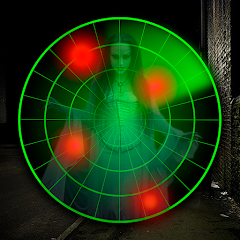
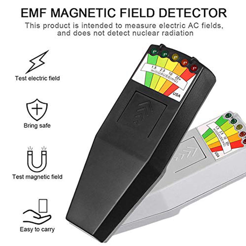
Inspired by the LED EMF Meter Magnetic Field Detector (which helps to measure electromagnetic fields to identify equipment that generates high radiation) used for “ghost hunting,” my goal was to create a device similar to a “ghost detector.” Well, at least that’s the idea! Right now, it’s really good at detecting shadows, brightness, and darkness. Originally, I prototyped it as a device to light up cabinets, drawers, and more. But with some tinkering, it might just find something spooky—spirits! (p.s. this is for last week’s assignment)
OVERVIEW
The prototype is designed to detect changes in light levels using a photoresistor. It consists of a photoresistor connected to analog pin A0 on the Arduino board. The prototype includes four LEDs connected to digital pins 2, 3, 4, and 5, which illuminate in response to different brightness levels read by the photoresistor. Further, based on the brightness level detected, the Arduino activates specific combinations of LEDs to indicate the brightness level or as i would like to say “ghosts”
const int thresholds[] = {600, 500, 400, 300};
If the brightness level exceeds the highest threshold, all four LEDs are illuminated, indicating maximum brightness.
If the brightness level exceeds the second highest threshold, the first three LEDs are illuminated, while the fourth LED remains off.
If the brightness level exceeds the third highest threshold, only the first two LEDs are illuminated, while the remaining LEDs are turned off.
If the brightness level exceeds the lowest threshold, only the first LED is illuminated, while the remaining LEDs are turned off.
If the brightness level falls below all thresholds, all LEDs are turned off.
IMPLEMENTATION
Prototype 1
As explained above, the photoresistor is able to detect the brightness level, to which range it belongs, and then the lights react accordingly. Do ghosts have shadows? Not necessarily… but anything is possible, so “use your imagination”. Perhaps it could even detect people or other moving objects.
Prototype 2
I know. We agreed not to use our hands, but no one mentioned anything about shadows. Here, I’m simply demonstrating the main concept of how it works. You could use your legs, face, or any other object. However, for the sake of a clear demonstration and a decent angle, I chose to use my hand’s shadow…not my hand.
Prototype 3
To further test its practicality, I decided to place it in my drawer. As you can see, it could prove quite useful with improved light adjustments.
CONCLUSION
It was certainly challenging to manage the numerous if-else cases and determine the appropriate ranges for the photoresistor. I invested a considerable amount of time debugging why certain LED lights functioned while others didn’t, only to realize that my else-if statements were not properly ordered, leading to skipped conditions. However, despite the constraint of not using our hands, I discovered a loophole, which allowed me to experiment with several of my ideas. (p.s. this is for last week’s assignment)
For this assignment, I wanted to recreate the human pulse / heartbeat. The blinking of the LEDs represents the ‘lub-dub’ sound of our heartbeat and the sound of the piezo buzzer represents our heart rate or pulse. When the button is pressed, the LEDs blink in a pattern synchronized with the buzzer. The potentiometer enables users to adjust the speed of the blinking pattern and the pitch of a piezo buzzer. So turning up the potentiometer symbolizes increasing the heart rate.
Video:
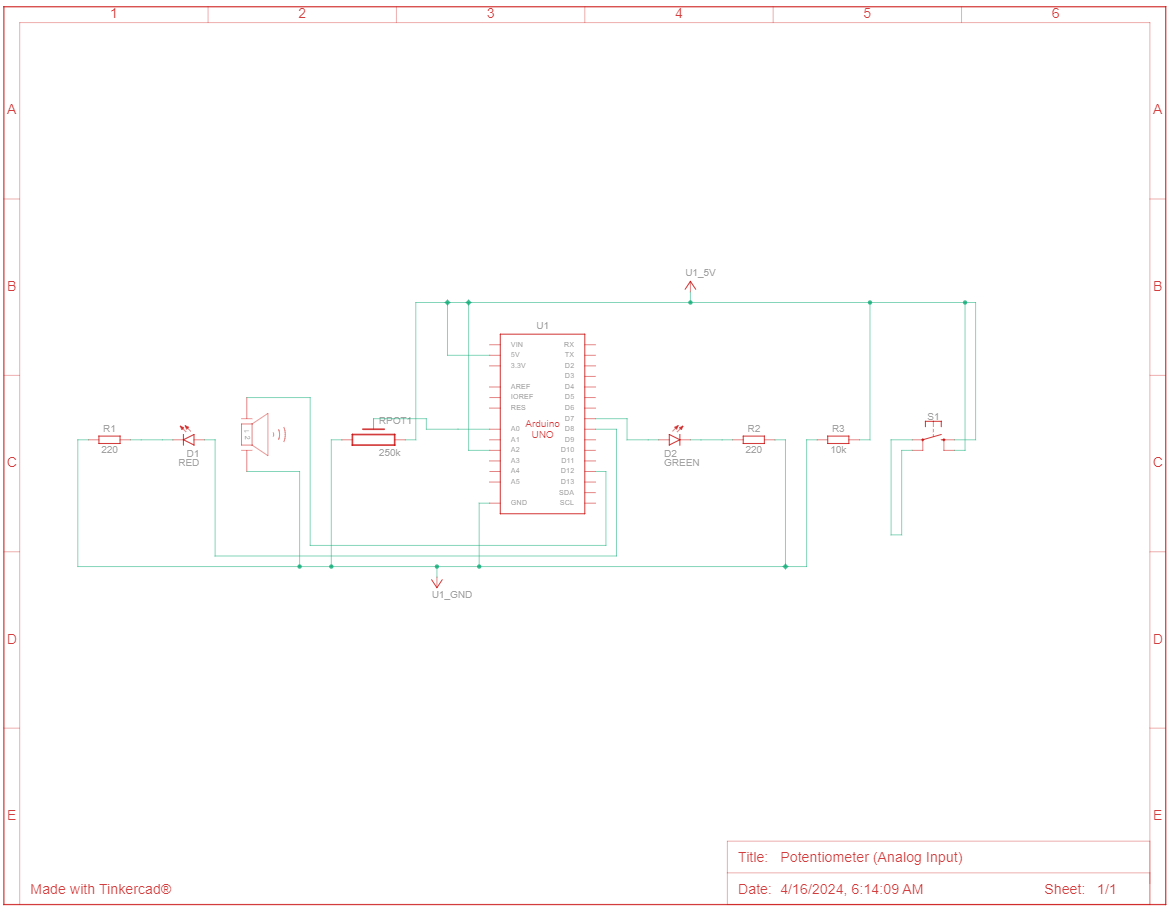
Schematic Diagram:
Arduino Code:
const int buttonPin = A2;
const int potentiometerPin = A0;
const int buzzerPin = 12;
const int ledPin1 = 7;   //red
const int ledPin2 = 8;   //green

int buttonState = LOW; //digital input
int potValue = 0;  //analog input
int blinkSpeed = 500; //LED blink speed

void setup() {
  pinMode(buttonPin, INPUT);
  pinMode(buzzerPin, OUTPUT);
  pinMode(ledPin1, OUTPUT);
  pinMode(ledPin2, OUTPUT);
}

void loop() {
  // Read the value of the potentiometer and map it to blink speed range (100-1000 ms)
  potValue = analogRead(potentiometerPin);
  blinkSpeed = map(potValue, 0, 1023, 100, 1000);

  buttonState = digitalRead(buttonPin);
  if (buttonState == HIGH) {  //button pressed
    blinkPattern();
    // Play a tone with frequency based on blink speed
    int buzzerFrequency = map(blinkSpeed, 100, 1000, 500, 1500);
    tone(buzzerPin, buzzerFrequency);
    delay(50);  // Buzz for 100 milliseconds
    noTone(buzzerPin);  // Turn off the buzzer
  } else { //button released
    digitalWrite(ledPin1, LOW);
    digitalWrite(ledPin2, LOW);
    noTone(buzzerPin);
  }
}

void blinkPattern() {
  digitalWrite(ledPin1, HIGH);
  delay(blinkSpeed);
  digitalWrite(ledPin1, LOW);
  digitalWrite(ledPin2, HIGH);
  delay(blinkSpeed);
  digitalWrite(ledPin2, LOW);
}
Overall, I am happy with the outcome. I was relieved to see it finally work because I was trying everything (debugging, restarting circuit, etc.) for 4 hours before I realized my 5V wasn’t connected in properly.
I further want to create more audio-visual displays using LEDs and the piezo buzzer.
For this Arduino class project, I set out to create a straightforward yet multifunctional night light. The design includes an automatic feature where the light adjusts its brightness based on the room’s lighting conditions, ensuring the perfect level of illumination at all times. Additionally, it features a manual override button that allows users to adjust the brightness to their preference through a different LED at any moment.
A highlight of some code that you’re particularly proud of:
const int lightSensorPin = A0;
const int buttonPin = 2;
const int redLED = 8;         // Red LED on digital pin 8 for on/off control
const int yellowLED = 9;      // Yellow LED on digital pin 9 for analog control
const int lightThreshold = 500;  // Light level threshold for the yellow LED
int lastButtonState = HIGH;
bool redLEDState = LOW;

void setup() {
  pinMode(lightSensorPin, INPUT);
  pinMode(buttonPin, INPUT_PULLUP);
  pinMode(redLED, OUTPUT);
  pinMode(yellowLED, OUTPUT);
}

void loop() {
  int lightLevel = analogRead(lightSensorPin);
  int buttonState = digitalRead(buttonPin);

  // Button controls the red LED
  if (buttonState == LOW && lastButtonState == HIGH) {
    // Toggle the red LED state
    redLEDState = !redLEDState;
    digitalWrite(redLED, redLEDState); // Set the red LED according to the toggled state
    delay(50); // Debounce delay
  }

  // Light sensor controls the yellow LED
  if(lightLevel < lightThreshold) {
    // If it's dark, set the yellow LED to a brightness proportional to the darkness
    int brightness = map(lightLevel, 0, lightThreshold, 255, 0);
    analogWrite(yellowLED, brightness);
  } else {
    // If it's light, turn off the yellow LED
    analogWrite(yellowLED, 0);
  }

  // Update last button state
  lastButtonState = buttonState;
}
Video of Project:
Reflection and ideas for future work or improvements:
Reflecting on this Arduino night light project, I initially hoped to make the visual structure more intriguing and implement the design in a more creative way. However, I’ve come to realize that I’m still in the process of getting comfortable with the actual wiring and coding aspects of the project, which consumed the majority of my time. Despite these challenges, I’m proud of the work I’ve accomplished. If I had more time to devote to this project, I would focus on better integrating the button’s functionality with the light sensor to create a more seamless interaction between user input and the device’s automatic responses. In the future, I aim to explore more sophisticated design and programming techniques that could enhance both the aesthetic and functional elements of projects like this, ensuring they are not only practical but also visually appealing.

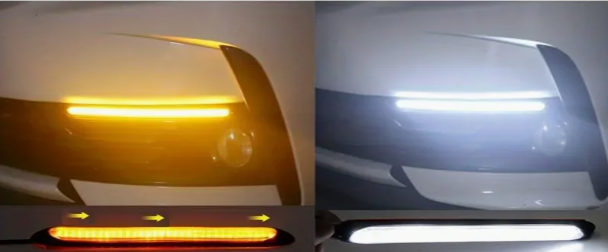
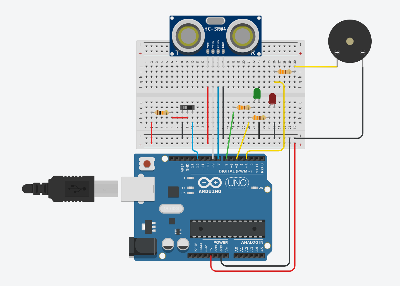 Figure 1: Component Simulation View
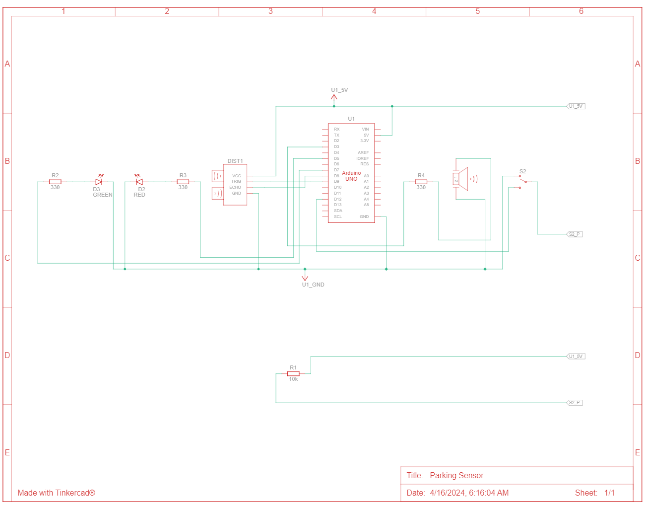 Figure 2: Schematic View
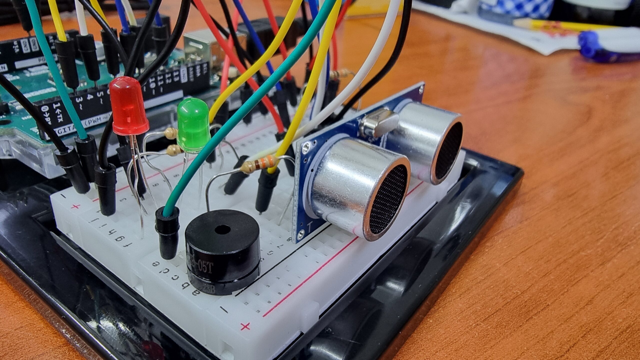 Figure 3: Front View
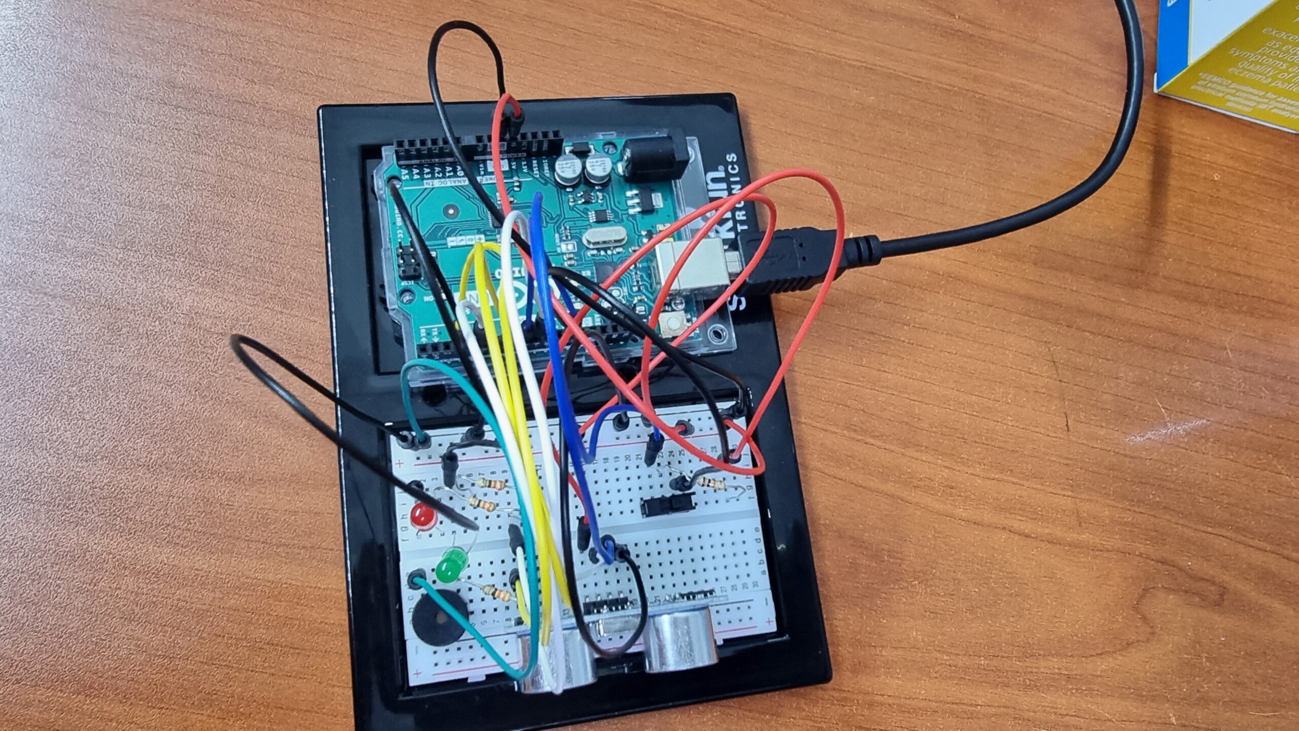 Figure 4: Top View
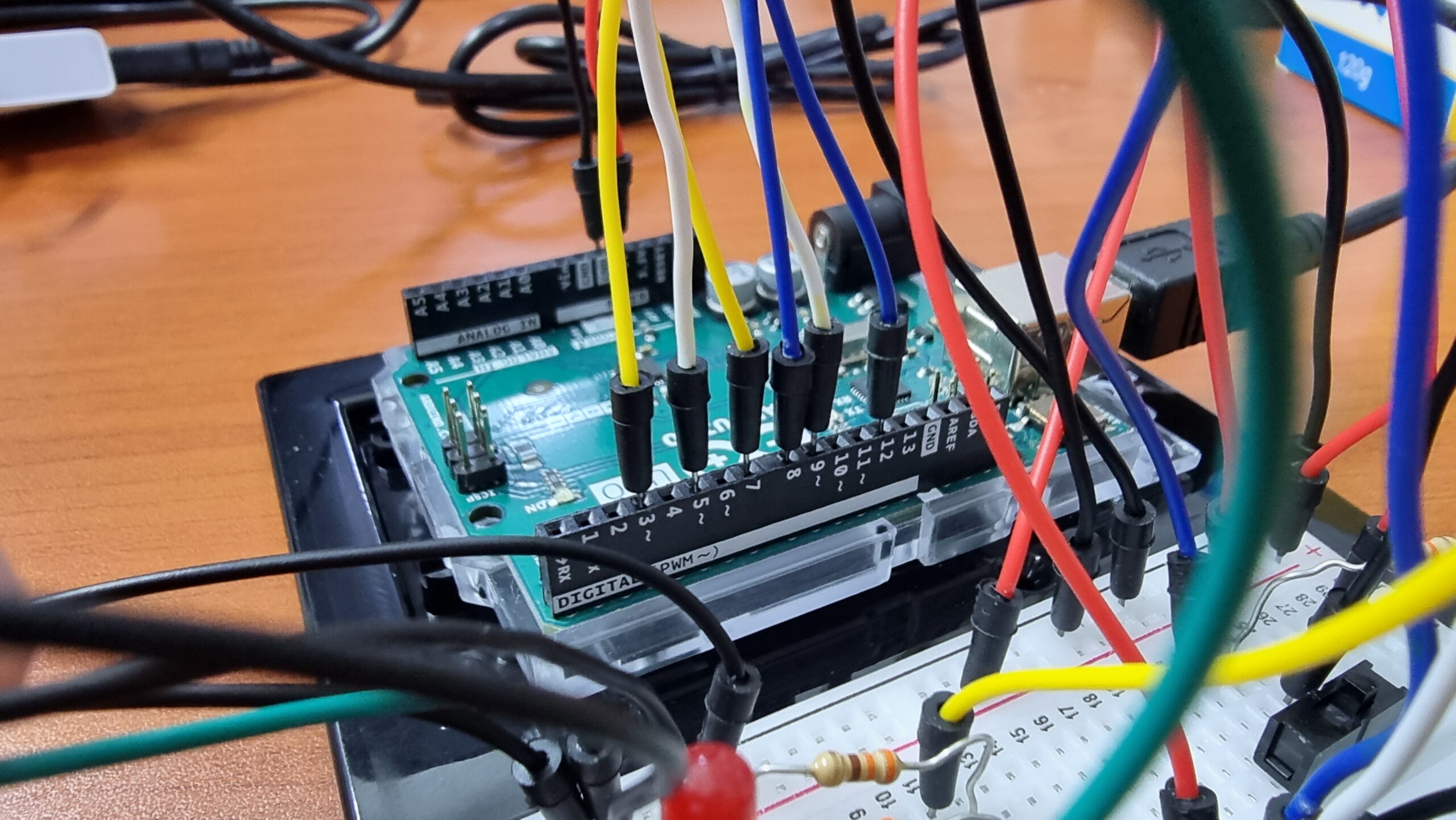 Figure 5: Arduino Pins Connection