Week 10 Assignment – light sensor

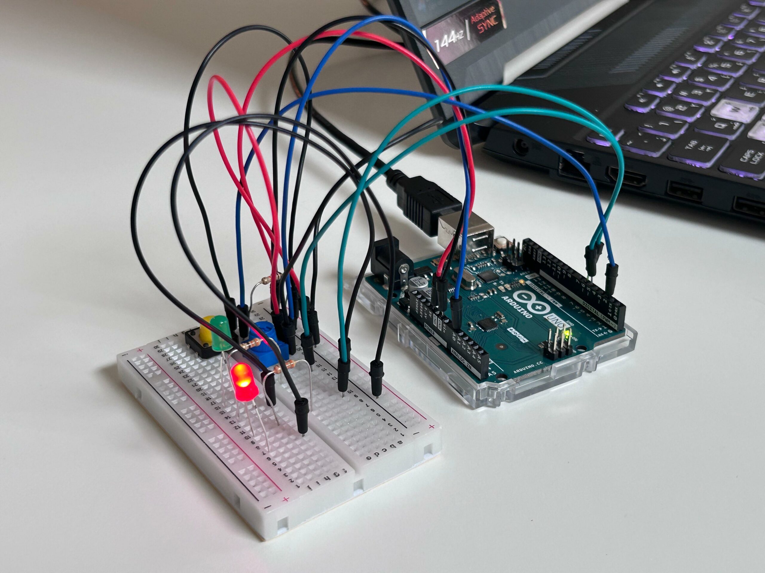
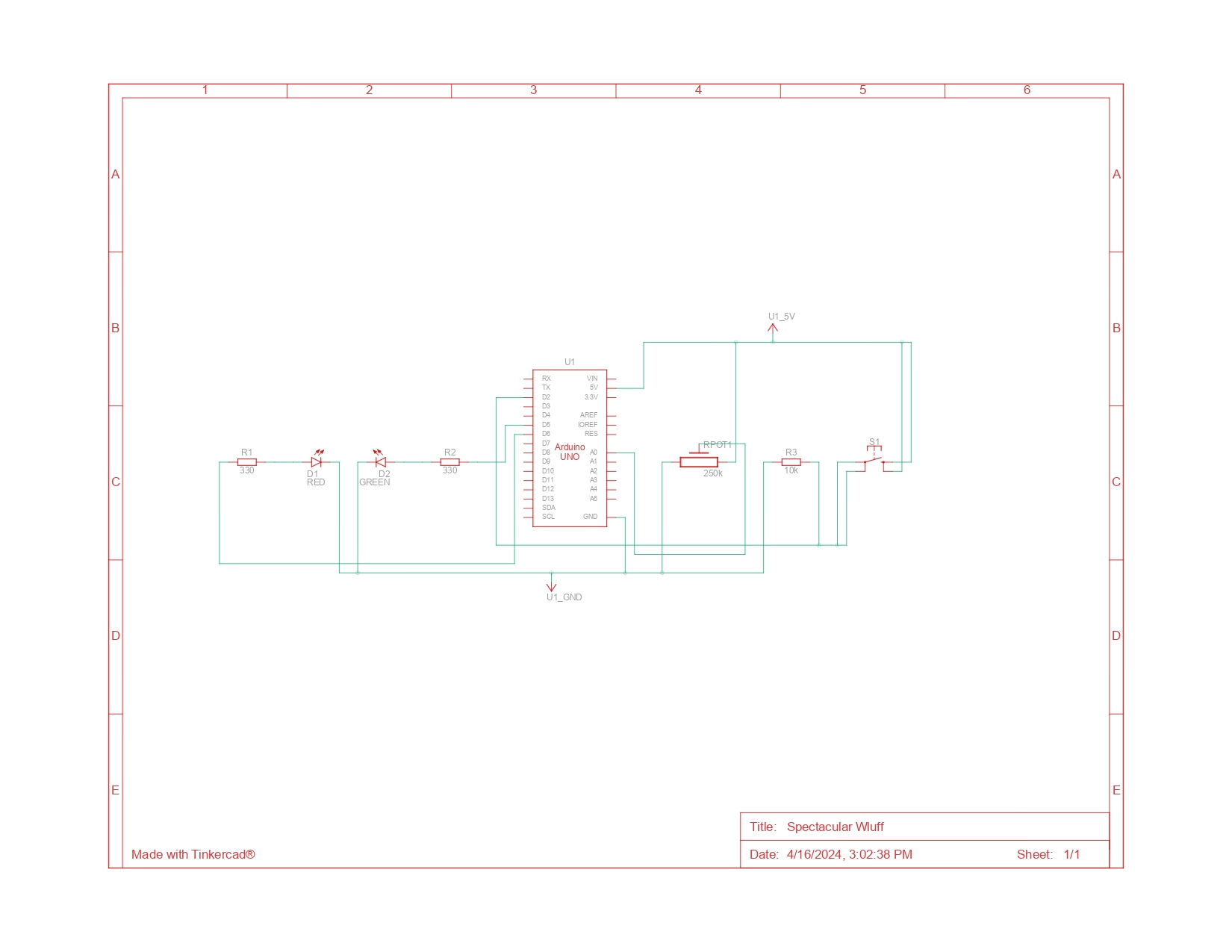
This projects concept is related to automatic lights, where a sensor detects the amount of light in its surroundings and according to it, it switches lights on and off. So for this assignment, I decided to implement this technique:

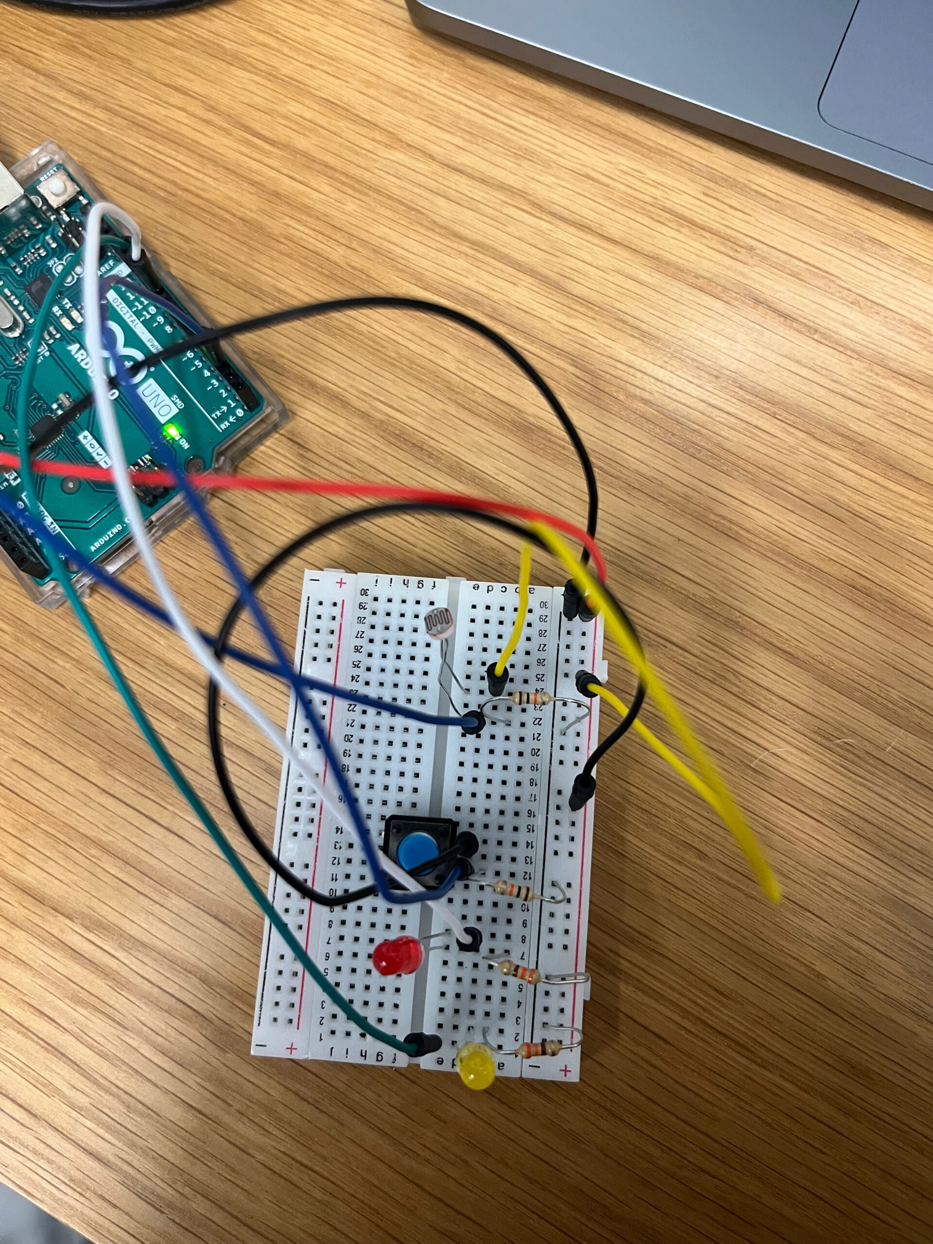
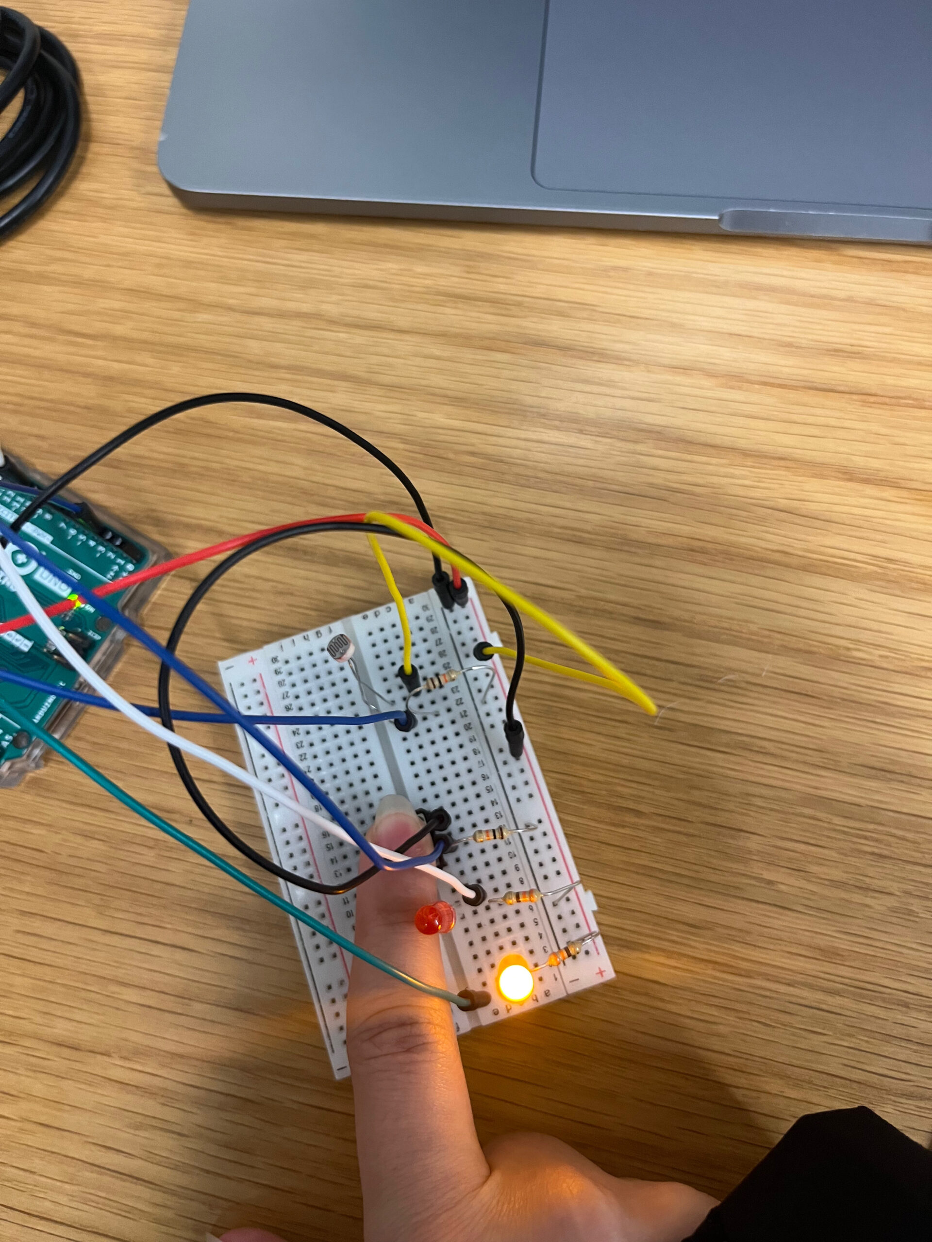
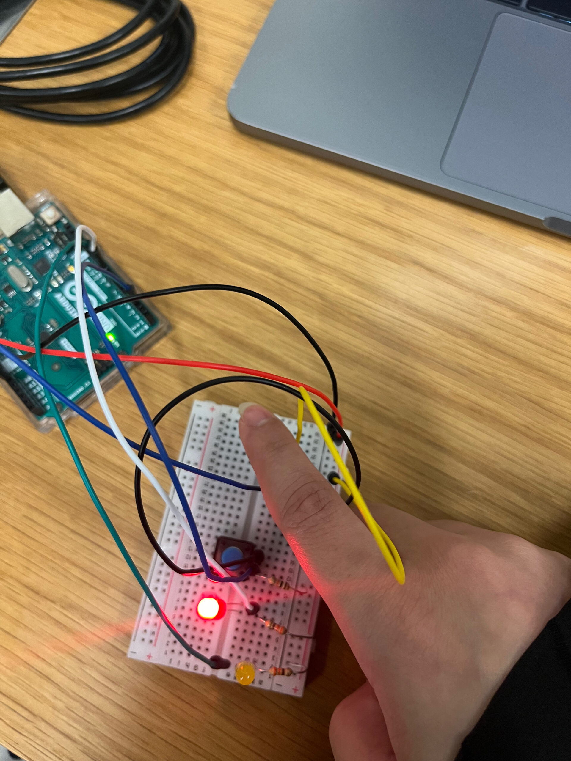
This is the code that I used to implement this method:

int photoSensorPin = A0;
int buttonPin = 2;
int ledPin1 = 9;
int ledPin2 = 10;
void setup() {
  pinMode(photoSensorPin, INPUT);
  pinMode(buttonPin, INPUT);
  pinMode(ledPin1, OUTPUT);
  pinMode(ledPin2, OUTPUT);
}
void loop() {
  int sensorValue = analogRead(photoSensorPin);
  int buttonState = digitalRead(buttonPin);
  if (buttonState == HIGH) {
    digitalWrite(ledPin1, LOW);
    digitalWrite(ledPin2, HIGH);
  } else if (sensorValue < 512) {
    digitalWrite(ledPin1, HIGH);
    digitalWrite(ledPin2, LOW);
  } else {
    digitalWrite(ledPin1, LOW);
    digitalWrite(ledPin2, LOW);
  }
}


Raya Tabassum: Reading Response 5

Tom Igoe’s reflections on recurring themes in physical computing projects highlight a vibrant field where creativity and technology meet. He encourages embracing projects even if they seem “done” because each iteration can bring new insights and innovations. From theremin-like instruments, which challenge creators to add meaningful physical interactions, to gloves and video mirrors that mix simplicity with potential for deeper engagement, these themes showcase the dynamic range of physical computing. It’s a call to think differently about what might seem mundane or overdone and to find one’s voice within well-trodden paths. This deeper engagement with the familiar challenges us to discover the unseen potentials in everyday ideas.

The other article by him named “Making Interactive Art: Set the Stage, Then Shut Up and Listen,” highlights a fundamental shift required for artists transitioning into interactive art. He stresses the importance of allowing the audience to engage and interact with the artwork without preconceived notions influenced by the artist’s own explanations. This approach champions a more open-ended exploration where the viewer’s personal experience and interpretation are paramount. This concept connects seamlessly with his views in “Physical Computing’s Greatest Hits (and misses),” where he encourages embracing well-worn themes with fresh perspectives. Both writings emphasize the creative potential in letting go of control—whether it’s about reinterpreting common project themes or allowing interactive artworks to speak for themselves through audience interaction.

Raya Tabassum: Emotional Room Temperature Indicator

Concept: This project combines analog and digital inputs to control LEDs in an innovative way. It’s an “Emotional Room Temperature Indicator”, which uses temperature data and user input to reflect the room’s “mood” with light.

Components Used:

  • Arduino Uno
  • TMP36 Temperature Sensor (Analog Sensor)
  • Push-button switch (Digital Sensor)
  • Standard LED (Digital LED)
  • RGB LED (Analog LED)
  • 220-ohm resistors for LEDs
  • 10k-ohm resistor for the button switch
  • Breadboard
  • Jumper wires

Implementation: I made a reel with description and uploaded as a YouTube shorts embedded below:

Programming:

#define LED_PIN 3
#define BUTTON_PIN 7
int redPin = 9; 
int greenPin = 10; 
int bluePin = 11;
int sensor = A0;

byte lastButtonState = LOW;
byte ledState = LOW;

unsigned long debounceDuration = 50; // millis
unsigned long lastTimeButtonStateChanged = 0;

void setup() {
  pinMode(LED_PIN, OUTPUT);
  pinMode(BUTTON_PIN, INPUT);
  pinMode(redPin, OUTPUT); 
  pinMode(greenPin, OUTPUT); 
  pinMode(bluePin, OUTPUT); 
  pinMode(sensor, INPUT);  // Reading sensor data

  Serial.begin(9600);  // Initialize serial communication at 9600 bits per second
}

int givetemp() {
  int reading = analogRead(sensor);
  float voltage = reading * 5.0 / 1024.0;
  float temperatureC = (voltage - 0.5) * 100;
  Serial.print(voltage); 
  Serial.print(" volts  -  ");
  Serial.print(temperatureC); 
  Serial.println(" degrees C  -  ");
  return (int)temperatureC;  // Convert float temperature to int before returning
}

void loop() {
  int currentTemp = givetemp();  // Call once and use the result multiple times

  if (currentTemp >= 20 && currentTemp <= 30) {
    digitalWrite(greenPin, HIGH);
    digitalWrite(bluePin, LOW);
    digitalWrite(redPin, LOW);
  } else if (currentTemp < 20) {
    digitalWrite(greenPin, LOW);
    digitalWrite(bluePin, HIGH);
    digitalWrite(redPin, LOW);
  } else if (currentTemp > 30) {
    digitalWrite(greenPin, LOW);
    digitalWrite(bluePin, LOW);
    digitalWrite(redPin, HIGH);
  }

  if (millis() - lastTimeButtonStateChanged > debounceDuration) {
    byte buttonState = digitalRead(BUTTON_PIN);
    if (buttonState != lastButtonState) {
      lastTimeButtonStateChanged = millis();
      lastButtonState = buttonState;
      if (buttonState == HIGH) {  // Assumes active HIGH button
        ledState = !ledState;  // Toggle the state
        digitalWrite(LED_PIN, ledState);
      }
    }
  }
}

Actual temperature of the room:

The TMP36 senses the room temperature. Depending on the “comfort” range (set here as 20°C to 30°C), the RGB LED changes colors — blue for cool, red for hot, and green for just right.
The push-button allows the user to set the mood of the room. When pressed, the standard yellow LED lights up to acknowledge that the room is at a comfortable temperature, while the RGB LED shows the current temperature-based mood of the room. The user can thus get immediate visual feedback on whether the room’s temperature is within a comfortable range or not.

Reading Response 7

The article “Physical Computing’s Greatest Hits (and misses)” offers an exploration of various classes of physical computing projects and the dynamics between implementation and engagement. The concept of “Meditation Helpers” caught my attention as someone interested in cognitive psychology and mindfulness. While these devices aim to guide users into a meditative state by measuring physiological indicators like heart rate and breath rate or stress through measuring sweat gland activity, I wonder about their effectiveness. Can technology truly facilitate mindfulness, or does it risk reducing meditation to a quantifiable metric? The reading prompted me to consider the role of technology in spiritual practices and whether it enhances or detracts from the essence of meditation. Another example that I found to be very innovative was Younghyun Chung’s “Digital Wheel Art”. I have always raised the question of accessibility in interactive installations. However, his project demonstrates that by utilizing technology to track and interpret bodily movements, individuals who may have limited mobility or dexterity can also engage in interactive experiences with greater ease and independence. Thus, physical computing can be leveraged to create inclusive and accessible solutions for individuals with disabilities. Another example of this is Sign Language gloves, which attempt to convert the motions of sign language into written or spoken words, which can help people who are deaf or hard of hearing to communicate easier with a hearing person.

Furthermore, the article prompted me to reconsider the essence of interactive art and its intrinsic connection to human emotions and experiences. The idea that interactive art should evoke feelings and thoughts rather than merely showcase technological prowess struck a chord with me. It reminded me that the true essence of art lies in its ability to stir emotions and provoke introspection, fostering a collaborative relationship between the artist and the audience. Overall, the article sparked a renewed curiosity in exploring the delicate balance between technical innovation and human connection in interactive art.


The article “Making Interactive Art” resonated with me deeply, particularly its emphasis on allowing the audience to interpret and engage with the work independently. It reminded me of my own experiences with interactive art installations, where the most impactful moments occurred when I was given the freedom to explore and interact without being told what to think or do. Like I mentioned earlier, art is truly interactive when there is open conversation between the artist and the viewer. In simple terms: show, don’t tell.

I appreciated the comparison the author drew between designing interactive art and directing actors in a performance. It highlighted the importance of providing the audience with tools and cues to guide their interaction while allowing room for individual interpretation and discovery. However, I found myself questioning whether there might be instances where some level of guidance or interpretation could enhance the audience’s experience without detracting from their autonomy. For example, some modern artworks look like random nonsense to me before I’m told the hidden meaning. 

Week 10 – Interactive/traditional switches

Project Concept:

Drawing inspiration from everyday objects and interactions, this assignment presents a simple light switch and dimmer found in most houses around the world. I’m reimagining these familiar components in a playful and interactive way using Arduino and LEDs. The dynamics consists of a modern twist on traditional controls, where pressing a button toggles the red LED while turning a knob adjusts the brightness of the green LED.

Materials:

  • Arduino Uno board
  • Jumper wires
  • Green LED
  • Red LED
  • Two 330 ohm resistors
  • One 10k ohm resistor
  • Push button
  • Potentiometer

Implementation: 

The circuit reflects the simplicity and functionality of a traditional light switch and dimmer. The push button acts as the on/off switch for the red LED, providing tactile feedback similar to pressing a light switch. Meanwhile, the potentiometer emulates the rotary dial of a dimmer, allowing users to adjust the brightness of the green LED by turning the knob.

Schematics:


Code:

const int SENSOR_PIN = A0; // Analog input pin for sensor controlling red LED brightness
const int CONTROL_PIN = 2; // Digital input pin for control button to switch LED colors
const int RED_LED = 5;  // Digital output pin for LED (red)
const int GREEN_LED = 6;  // Digital output pin for LED (green)

int redBrightness = 0; // Red LED brightness controlled by sensor
bool buttonPressed = false; // Button state
int colorIndex = 0; // Index of current color

void setup() {
  pinMode(SENSOR_PIN, INPUT);
  pinMode(CONTROL_PIN, INPUT_PULLUP);
  pinMode(RED_LED, OUTPUT);
  pinMode(GREEN_LED, OUTPUT);
}

void loop() {
  // Read sensor value to control brightness of red LED
  redBrightness = analogRead(SENSOR_PIN) / 4; // Divide by 4 to map 0-1023 to 0-255
  
  // Set the brightness of the red LED
  analogWrite(RED_LED, redBrightness);
  
  // Check control button state
  if (digitalRead(CONTROL_PIN) == LOW) {
    if (!buttonPressed) {
      // Toggle color index
      colorIndex = (colorIndex + 1) % 2;
      buttonPressed = true;
      
      // Turn on green LED when button is pressed
      digitalWrite(GREEN_LED, HIGH);
    }
  } else {
    buttonPressed = false;
    // Turn off green LED when button is released
    digitalWrite(GREEN_LED, LOW);
  }
}


Video Demonstration:

Reflection and Improvements:

Finally, I’m satisfied with the project outcome, as it bridges the gap between simplicity and innovation, reimagining everyday objects in a playful and interactive manner while showcasing the creative potential of Arduino-based projects. Some improvements are as follow:

  • Experiment with different button and knob designs to enhance user experience and aesthetic appeal.
  • Integrate additional sensors, such as light sensors or temperature sensors, to create more dynamic lighting effects and automation capabilities.

production assignment week 10

This project allows us to control the brightness of two LEDs – one red and one green – using a potentiometer and a push button.

Here’s what you’ll see in the video:
An Arduino Uno board.
A potentiometer, acting as a dimmer switch.
A push button for an instant override.
Two LEDs, red and green, responding to our commands.

How does it work?
Let’s dive into the details:
The Potentiometer: As you turn the knob, it sends varying voltage values to the Arduino. The code interprets these values and maps them to control the brightness of the LEDs. Turning one way brightens the green LED while dimming the red, and vice versa.
The Push Button: This acts as an override switch. No matter what the potentiometer setting is, pressing the button instantly turns the red LED on to full brightness.

Technical Insights:
The project utilizes the Arduino’s analog input capabilities to read the potentiometer values and its PWM (Pulse Width Modulation) functionality to control the LED brightness.
The push button is connected to a digital input pin, allowing the Arduino to detect button presses and trigger the override function.

void loop() {
  int sensorValue = analogRead(A0);
  buttonState = digitalRead(btn);
    brightness = map(sensorValue,0,1023,0,255);

  brightness2 = map(sensorValue,0,1023,255,0);

  analogWrite(led,brightness);
    analogWrite(led2, brightness2);

  if (buttonState == HIGH) {
      analogWrite(led,255);
  }

  Serial.println(sensorValue);

}


Week #10 Assignment

Concept: 
For this assignment, I decided to implement the things that I have already learned in regards to the ultrasonic sensor and add the button. I wanted to see how far I can go with my knowledge.
Implementation:
The implementation was pretty easy, as I have used the previous assignment as an example. I just added the button and changed the code and voila!
End result:

Code:

//Intro to IM - Stefania Petre
// Define LED pins
int ledPin[3] = {8};

// Define Ultrasonic sensor pins
const int trigPin = 2; // or any other unused digital pin
const int echoPin = 3; // or any other unused digital pin

const int buttonPin = 13;
int buttonState = HIGH;
int lastButtonState = HIGH;
long lastDebounceTime = 0;
long debounceDelay = 50;
int pushCounter = 0;
int numberOfLED = 3;

void setup() {
  pinMode(buttonPin, INPUT);
  digitalWrite(buttonPin, HIGH); // Activate internal pull-up resistor
  
  // Set up LED pins
  for (int i = 0; i < numberOfLED; i++) {
    pinMode(ledPin[i], OUTPUT);
  }
  
  // Set up Ultrasonic sensor pins
  pinMode(trigPin, OUTPUT); // Sets the trigPin as an OUTPUT
  pinMode(echoPin, INPUT);  // Sets the echoPin as an INPUT
}

void loop() {
  int reading = digitalRead(buttonPin);

  // Check if the button state has changed
  if (reading != lastButtonState) {
    // Reset the debounce timer
    lastDebounceTime = millis();
  }

  // Check if the debounce delay has passed
  if ((millis() - lastDebounceTime) > debounceDelay) {
    // If the button state has changed, update the button state
    if (reading != buttonState) {
      buttonState = reading;

      // If the button state is LOW (pressed), increment pushCounter
      if (buttonState == LOW) {
        pushCounter++;
      }
    }
  }

  // Update the last button state
  lastButtonState = reading;

  // Turn off LED
  for (int i = 0; i < numberOfLED; i++) {
    digitalWrite(ledPin[i], LOW);
  }

  // Perform Ultrasonic sensor reading
  long duration, distance;
  digitalWrite(trigPin, LOW);
  delayMicroseconds(2);
  digitalWrite(trigPin, HIGH);
  delayMicroseconds(10);
  digitalWrite(trigPin, LOW);
  duration = pulseIn(echoPin, HIGH);
  distance = (duration * 0.0343) / 2; // Calculate distance in cm

  // Perform actions based on distance measured
  if (distance < 30) {
    // Turn on LED
    digitalWrite(ledPin[0], HIGH);
 

  // Delay before next iteration
  delay(100); // Adjust as needed
}

Comments:

Even though I got it to work, I still would have liked it to change colors depending on the distance from the sensor. I will try to implement that next time!

Week 10 | Beyond Ideas

I started picking up my first console when I was around four years old. It was Nintendo’s Gameboy Advance console. To this day, I still remember my first time inserting the cartridges, booting up the machine, and blasting hours and hours into Pokémon FireRed. The feeling of being immersed into an alternate world despite it being on a screen a few inches wide, and with few buttons to press, still blows my mind.

Nintendo-Game-Boy-Advance-Purple-FL

Gameboy Advance. Nintendo.

Even if it’s just 8 buttons, the console opened a rift to a new reality

Igoe clarifies that interactivity should be a gateway to endless possibilities rather than a fixated destination. Similarly, the console’s interactiveness only goes as far as the buttons and screen, yet game developers utilize those mechanics to propel the user one step closer to experiencing the Kanto Region (Pokémon FireRed’s world).

Video games, to me, are a new type of art–a premature one that is. Unlike paintings, books, or movies, it is a medium of art that takes shape by the user, rather than the author. Plus, because of how young they are, there is still room for the medium to grow.

I was thinking about how physical computing machines mentioned in Igoe’s post are not commercialized. Because these are new ideas, they still require rigorous testing and adjustments to fit our society. Yet, video game console challenges this idea. Floor dances, gloves, VR headsets, all these new devices are the pillars of future technologies. Hence, is it not better for us to embrace it as soon as possible?

Week 10 Production Assignment – Tea Temperature

For this week’s production assignment I wanted to experiment with a component that I have not yet used. The one component I had in mind for this was the temperature sensor. As I enjoy drinking tea, I decided to implement a circuit which gauges the presence and temperature of a liquid.

In order to do this, I created a series of if statements that test the temperature read by the sensor. While the technical aspect of this was manageable, the practical side was challenging. This was due to the unreliability of the sensor as it would read fluctuating and incorrect temperatures. Despite this, I was able to get some successful examples by restarting the circuit (and therefore restarting the sensor’s input). This is seen in the example below. The if statements are included below as well.

const int rgbRED_PIN = 9;//the digital pin for red pin
const int rgbGREEN_PIN = 10;//the digital pin for green pin
const int rgbBLUE_PIN = 11;//the digital pin for blue pin
const int temperaturePin = 0;//the analog read pin that is used to reat the temperature 
const int waterPin = 12;  
const int greenLED_Pin = 13;
 
void setup()
{
 
  pinMode(rgbRED_PIN, OUTPUT);
  pinMode(rgbGREEN_PIN, OUTPUT);
  pinMode(rgbBLUE_PIN, OUTPUT);
  pinMode(waterPin, INPUT);
  pinMode(greenLED_Pin, OUTPUT);
  Serial.begin(9600);//the bound rate for serial monitor 
  
}
 
 
void loop()
{
 
   int waterDetected = digitalRead(waterPin);
     if (waterDetected == HIGH) {
    digitalWrite(greenLED_Pin, HIGH);
  } else {
    digitalWrite(greenLED_Pin, LOW);
  }

  float voltage, degreesC, degreesF;//get numbers with decimals 
 
  voltage = getVoltage(temperaturePin);//get voltage from the temperature pin
  degreesC = (voltage - 0.5) * 100.0;//calculate the celcius degree
  degreesF = degreesC * (9.0/5.0) + 32.0;// calculate the Fahrenheit degree
 
  Serial.print("voltage: ");//print volrage in serial monitor
  Serial.print(voltage);
  Serial.print("  deg C: ");//print the celcious degree in serial monitor
  Serial.println(degreesC);
 
 
  if (degreesC < 23) //if the temperature is less than 23 degrees C turn off RGB
  {
  // Off (all LEDs off):
    digitalWrite(rgbRED_PIN, LOW);
    digitalWrite(rgbGREEN_PIN, LOW);
    digitalWrite(rgbBLUE_PIN, LOW);
  }
 
  
if (degreesC >= 24)//if the temperature is larger than 24 degrees C show purple
  {
  digitalWrite(rgbRED_PIN, HIGH);
  digitalWrite(rgbGREEN_PIN, LOW);
  digitalWrite(rgbBLUE_PIN, HIGH);
  }
}


float getVoltage(int pin)//get voltage 
 
 {
  return (analogRead(pin) * 0.004882814);// conver 0 to 1023 value to 0 to 5 value (the true voltage)
 }


One point that I could not manage was the water detection aspect which I wanted to incorporate into this circuit. I attempted to do so by connecting alligator clips into a cup of water in order to complete the circuit. The LED would flicker occasionally but would not stay on consistently. I am unsure whether this is due to the connection of the alligator clips (other examples I have seen use regular wires) or because of the way I had wired the circuit itself.

Week 10 – Assignment

The project is designed as a competitive game using an Arduino board to determine who can activate their respective LED faster: a player pressing a button or an automated response triggered by a photoresistor detecting darkness. The setup includes two LEDs connected to the Arduino. One LED (connected to pin 10) is controlled by a pushbutton, which, when pressed, signifies the  player’s reaction. The other LED (connected to pin 9) is controlled by a photoresistor, representing an automated “player” that reacts to the absence of light. The game’s objective is to see which mechanism can activate its LED first under the given conditions—either when it becomes dark enough for the photoresistor to react or when the human player presses the button.

This was a lot of fun to make and the concept sort of formed as I put everything together, I mostly focused on using the class notes as a resources however I did use some of the examples on the official Arduino website. 

https://forum.arduino.cc/t/using-an-led-and-a-photoresistor-to-switch-itself-on-and-off/179690

https://projecthub.arduino.cc/agarwalkrishna3009/arduino-diy-led-control-with-ldr-sensor-photoresistor-fa011f

int photoSensorPin = A0;
int buttonPin = 2;
int ledPin1 = 9;
int ledPin2 = 10;

void setup() {
  pinMode(photoSensorPin, INPUT);
  pinMode(buttonPin, INPUT);
  pinMode(ledPin1, OUTPUT);
  pinMode(ledPin2, OUTPUT);
}

void loop() {
  int sensorValue = analogRead(photoSensorPin);
  int buttonState = digitalRead(buttonPin);

  if (buttonState == HIGH) {
    digitalWrite(ledPin1, LOW);
    digitalWrite(ledPin2, HIGH);
  } else if (sensorValue < 512) {
    digitalWrite(ledPin1, HIGH);
    digitalWrite(ledPin2, LOW);
  } else {
    digitalWrite(ledPin1, LOW);
    digitalWrite(ledPin2, LOW);
  }
}