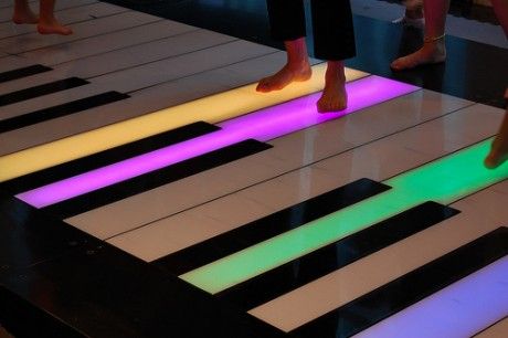
Replicating the piano playing mat that we all used to play as children was the idea behind this assignment. Even those who are not musically inclined are drawn to play with the piano mat again because of how logically it was created. Why not make something that makes us all feel nostalgic, rather than just one of us? You’ll be overwhelmed with happiness as you play about with our design and hopefully be able to relive all your childhood memories in a way. This initiative will facilitate audience engagement and provide a means of connection to one another.
The code is for an Arduino setup that uses an ultrasonic sensor to measure distance and a force-sensitive resistor to detect pressure. It plays different musical notes based on the distance measured by the sensor, but only if a certain pressure threshold is exceeded on the resistor. If the measured distance is out of a specified range or the pressure is too low, no sound is played. The system uses this setup to create an interactive musical device where sound changes with distance and pressure.
int trig = 10;

int echo = 11;

long duration;

long distance;

int force;


void setup() {

  pinMode(echo, INPUT);


  pinMode(trig, OUTPUT);


  Serial.begin(9600);

}


void loop() {

  digitalWrite(trig, LOW); //triggers on/off and then reads data

  delayMicroseconds(2);

  digitalWrite(trig, HIGH);

  delayMicroseconds(10);

  digitalWrite(trig, LOW);

  duration = pulseIn(echo, HIGH);

  distance = (duration / 2) * .0344;    //344 m/s = speed of sound. We're converting into cm


  int notes[7] = {261, 294, 329, 349, 392, 440, 494}; //Putting several notes in an array

  //          mid C  D   E   F   G   A   B


  force = analogRead(A0); //defining force as FSR data


  if (distance < 0 || distance > 50 || force < 100) { //if not presed and not in front


    noTone(12); //dont play music


  }


  else if ((force > 100)) {  //if pressed


    int sound = map(distance, 0, 50, 0, 6);  //map distance to the array of notes

    tone(12, notes[sound]);  //call a certain note depending on distance


  }


}
Reflections & Challenges:
One of the challenges we had while working on this project was the weakness of the sensors; if we had an ultrasonic sensor that measured the distance longer and a larger force detecting resistor, we would not have had any trouble playing notes. Therefore, we were forced to limit the user to playing notes (C-D-E-F-G-A) as a result of this.
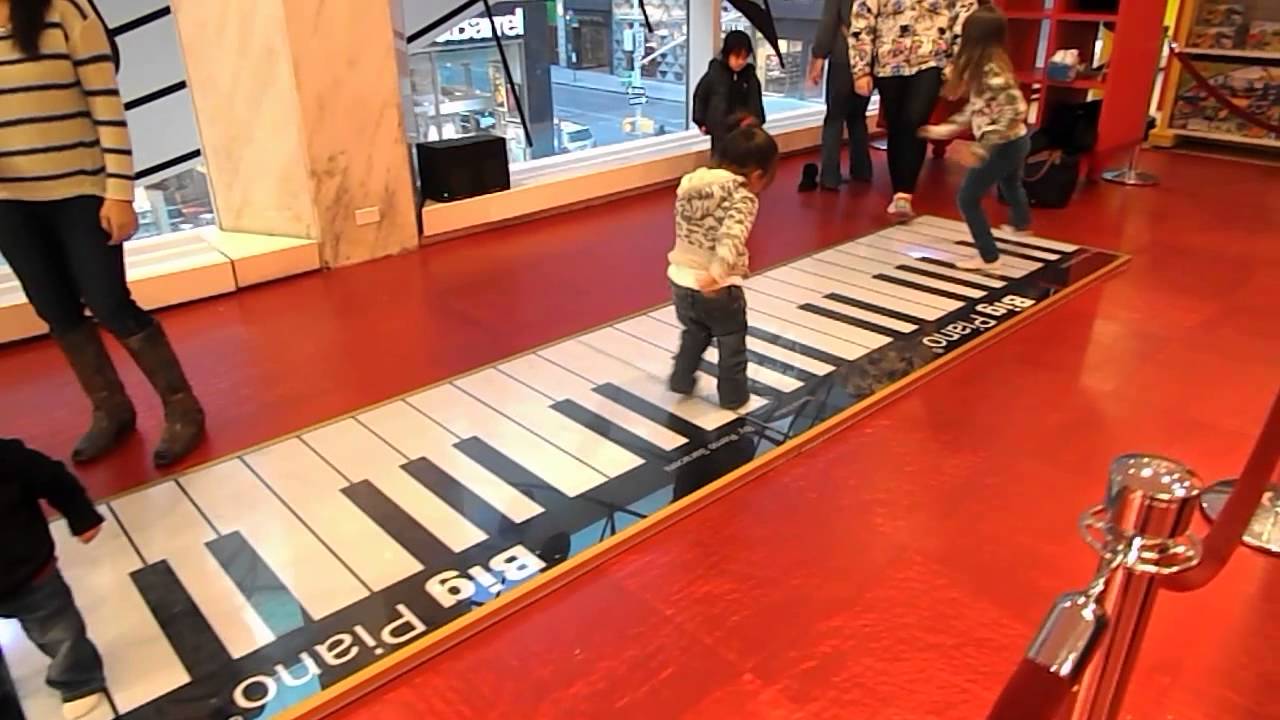
Replicating the piano playing mat that we all used to play as children was the idea behind this assignment. Even those who are not musically inclined are drawn to play with the piano mat again because of how logically it was created. Why not make something that makes us all feel nostalgic, rather than just one of us? You’ll be overwhelmed with happiness as you play about with our design and hopefully be able to relive all your childhood memories in a way. This initiative will facilitate audience engagement and provide a means of connection to one another.
Code:
The code is for an Arduino setup that uses an ultrasonic sensor to measure distance and a force-sensitive resistor to detect pressure. It plays different musical notes based on the distance measured by the sensor, but only if a certain pressure threshold is exceeded on the resistor. If the measured distance is out of a specified range or the pressure is too low, no sound is played. The system uses this setup to create an interactive musical device where sound changes with distance and pressure.
int trig = 10;
int echo = 11;
long duration;
long distance;
int force;

void setup() {
  pinMode(echo, INPUT);

  pinMode(trig, OUTPUT);

  Serial.begin(9600);
}

void loop() {
  digitalWrite(trig, LOW); //triggers on/off and then reads data
  delayMicroseconds(2);
  digitalWrite(trig, HIGH);
  delayMicroseconds(10);
  digitalWrite(trig, LOW);
  duration = pulseIn(echo, HIGH);
  distance = (duration / 2) * .0344;    //344 m/s = speed of sound. We're converting into cm


  int notes[7] = {261, 294, 329, 349, 392, 440, 494}; //Putting several notes in an array
  //          mid C  D   E   F   G   A   B

  force = analogRead(A0); //defining force as FSR data


  if (distance < 0 || distance > 50 || force < 100) { //if not presed and not in front

    noTone(12); //dont play music

  }

  else if ((force > 100)) {  //if pressed

    int sound = map(distance, 0, 50, 0, 6);  //map distance to the array of notes
    tone(12, notes[sound]);  //call a certain note depending on distance

  }


}
Reflections & Challenges:
One of the challenges we had while working on this project was the weakness of the sensors; if we had an ultrasonic sensor that measured the distance longer and a larger force detecting resistor, we would not have had any trouble playing notes. Therefore, we were forced to limit the user to playing notes (C-D-E-F-G-A) as a result of this.
Replicating the piano playing mat that we all used to play as children was the idea behind this assignment. Even those who are not musically inclined are drawn to play with the piano mat again because of how logically it was created. Why not make something that makes us all feel nostalgic, rather than just one of us? You’ll be overwhelmed with happiness as you play about with our design and hopefully be able to relive all your childhood memories in a way. This initiative will facilitate audience engagement and provide a means of connection to one another.
The code is for an Arduino setup that uses an ultrasonic sensor to measure distance and a force-sensitive resistor to detect pressure. It plays different musical notes based on the distance measured by the sensor, but only if a certain pressure threshold is exceeded on the resistor. If the measured distance is out of a specified range or the pressure is too low, no sound is played. The system uses this setup to create an interactive musical device where sound changes with distance and pressure.
int trig = 10;

int echo = 11;

long duration;

long distance;

int force;


void setup() {

  pinMode(echo, INPUT);


  pinMode(trig, OUTPUT);


  Serial.begin(9600);

}


void loop() {

  digitalWrite(trig, LOW); //triggers on/off and then reads data

  delayMicroseconds(2);

  digitalWrite(trig, HIGH);

  delayMicroseconds(10);

  digitalWrite(trig, LOW);

  duration = pulseIn(echo, HIGH);

  distance = (duration / 2) * .0344;    //344 m/s = speed of sound. We're converting into cm


  int notes[7] = {261, 294, 329, 349, 392, 440, 494}; //Putting several notes in an array

  //          mid C  D   E   F   G   A   B


  force = analogRead(A0); //defining force as FSR data


  if (distance < 0 || distance > 50 || force < 100) { //if not presed and not in front


    noTone(12); //dont play music


  }


  else if ((force > 100)) {  //if pressed


    int sound = map(distance, 0, 50, 0, 6);  //map distance to the array of notes

    tone(12, notes[sound]);  //call a certain note depending on distance


  }


}
Reflections & Challenges:
One of the challenges we had while working on this project was the weakness of the sensors; if we had an ultrasonic sensor that measured the distance longer and a larger force detecting resistor, we would not have had any trouble playing notes. Therefore, we were forced to limit the user to playing notes (C-D-E-F-G-A) as a result of this.
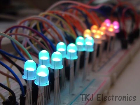
I am not sure how feasible is this idea. However, I want to display the silhouettes of the hand’s actions through the LED lights. As the hand moves, the lights will light up based on the changes of location of the hand. Below is an illustration of the idea:
The way the hand moves will decide on how the light will behave. I am intending to use the ML5 library from p5.js to track the hand movements. The data return from the library function will be mapped into the LED lights that will light up accordingly.
Map Drawing
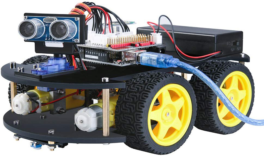
I want to have p5js as a drawing tool that can decide on the path that the 4-wheel motor model can run on. However, I want this to be drawn using the hands in the air, using different libraries in p5js. Then the data can be transferred to the model to allow the motor to run. Also, the model will have distance sensor to detect any blockage in the pathway to stop accordingly.
Bret Victor’s “A Brief Rant on the Future of Interaction Design” emphasizes touchscreen technology. His critique resonates deeply with those of us concerned about the narrow trajectory of technological innovation where tactile and kinesthetic interaction is marginalized in favor of visually dominated interfaces. Victor’s call for broader sensory involvement in technological interfaces is a plea for innovation and an argument rooted in the natural human interaction with the world. Evidence supports his viewpoint from various fields, including educational psychology, which suggests that multi-sensory learning environments enhance understanding and retention (Wolfe and Nevills). This aligns with Victor’s advocacy for interfaces that engage more of our bodily senses, not less.
Victor’s reflections and the subsequent responses to his original piece stimulate a broader conversation about the potential biases in technology design. His critique may seem biased to those who champion digital minimalism and current devices’ sleek, streamlined aesthetics. However, it raises an essential question about whom technology is truly serving. Has reading his arguments changed my beliefs? Absolutely. It’s led me to reconsider the role of physicality in digital interaction and consider the untapped possibilities of interfaces that could mimic more complex human behaviors and interactions. This reflection opens up questions about the potential for future technologies: How far can we push the boundaries of interaction design to make digital experiences more immersive and intuitive without sacrificing functionality? How can designers balance the need for advanced functionality with intuitive physical interactions?
Citation:
Wolfe, P., & Nevills, P. (2004). Building the reading brain, PreK-3. Corwin Press.
The concept of this project was to create a mini drum pad, or what is equivalent to one, with the hardware we have available. The device would use buttons to trigger different buzzer sounds, mimicking the functionality of a traditional drum pad. Each button on the device would correspond to a different sound, with the frequency of these sounds adjustable via a potentiometer. This allows the user to modify the pitch of the tones.
Code:
// Defining pins assignments for buttons and buzzers
const int buttonPin1 = 2;
const int buttonPin2 = 3;
const int buttonPin3 = 4;
// Coded with the Aid of ChatGPT
const int buttonPin4 = 5; // Monitoring and playbacks button
// Coded with the Aid of ChatGPT
const int buzzerPin1 = 8;
const int buzzerPin2 = 9;
const int buzzerPin3 = 10;
const int potPin = A0; // Potentiometer connected to A0 for frequency control

// Variables to manage button states and debounce timing
int buttonState1 = 0;
int lastButtonState1 = 0;
int buttonState2 = 0;
int lastButtonState2 = 0;
int buttonState3 = 0;
int lastButtonState3 = 0;
int buttonState4 = 0;
int lastButtonState4 = 0;

unsigned long lastDebounceTime1 = 0;
unsigned long lastDebounceTime2 = 0;
unsigned long lastDebounceTime3 = 0;
unsigned long lastDebounceTime4 = 0;
unsigned long debounceDelay = 50; // Debounce delay in milliseconds

// Struct to hold buzzer activation data including the pin and frequency
struct BuzzerAction {
  int buzzerPin;
  int frequency;
};

// Coded with the Aid of ChatGPT
BuzzerAction record[100]; // Array to store each buzzer activation
int recordIndex = 0; // Index for recording array
//Coded with the Aid of ChatGPT

void setup() {
  // Initialize all button and buzzer pins
  pinMode(buttonPin1, INPUT);
  pinMode(buttonPin2, INPUT);
  pinMode(buttonPin3, INPUT);
// Coded with the Aid of ChatGPT
  pinMode(buttonPin4, INPUT);
// Coded with the Aid of ChatGPT
  pinMode(buzzerPin1, OUTPUT);
  pinMode(buzzerPin2, OUTPUT);
  pinMode(buzzerPin3, OUTPUT);
  pinMode(potPin, INPUT); // Setups potentiometer pin as input
}

void loop() {
  // Reads current state of buttons
  int reading1 = digitalRead(buttonPin1);
  int reading2 = digitalRead(buttonPin2);
  int reading3 = digitalRead(buttonPin3);
// Coded with the Aid of ChatGPT
  int reading4 = digitalRead(buttonPin4);
// Coded with the Aid of ChatGPT
  int potValue = analogRead(potPin); // Reads potentiometer value
  int frequency = map(potValue, 0, 1023, 200, 2000); // Maps potentiometer value to frequency range

  // Handle button 1 press and recording
  debounceAndRecord(reading1, &lastButtonState1, &buttonState1, &lastDebounceTime1, buzzerPin1, frequency);

  // Handle button 2 press and recording
  debounceAndRecord(reading2, &lastButtonState2, &buttonState2, &lastDebounceTime2, buzzerPin2, frequency);

  // Handle button 3 press and recording
  debounceAndRecord(reading3, &lastButtonState3, &buttonState3, &lastDebounceTime3, buzzerPin3, frequency);

  // Handles button 4 for playback
  if (reading4 != lastButtonState4) {
    lastDebounceTime4 = millis();
  }
  if ((millis() - lastDebounceTime4) > debounceDelay) {
    if (reading4 != buttonState4) {
      buttonState4 = reading4;
      if (buttonState4 == HIGH) {
        for (int i = 0; i < recordIndex; i++) {
          // Play each recorded buzzer action with the specific frequency recorded
          tone(record[i].buzzerPin, record[i].frequency, 200);
          delay(250); // Short delay between each buzzer action for clarity
        }
        recordIndex = 0; // Resets record index after playback
      }
    }
  }

  // Update last button states for next loop iteration
  lastButtonState1 = reading1;
  lastButtonState2 = reading2;
  lastButtonState3 = reading3;
  lastButtonState4 = reading4;
}
// Coded with the Aid of ChatGPT
// Function to handle button debouncing and recording buzzer actions
void debounceAndRecord(int reading, int *lastButtonState, int *buttonState, unsigned long *lastDebounceTime, int buzzerPin, int frequency) {
  if (reading != *lastButtonState) {
    *lastDebounceTime = millis(); // Reset debounce timer
  }
  if ((millis() - *lastDebounceTime) > debounceDelay) {
    if (reading != *buttonState) {
      *buttonState = reading; // Updates button state
      if (*buttonState == HIGH && recordIndex < sizeof(record) / sizeof(record[0])) {
        record[recordIndex++] = {buzzerPin, frequency}; // Records the buzzer activation
        tone(buzzerPin, frequency, 200); // Plays buzzer at recorded frequency
      }
    }
  }
  *lastButtonState = reading; // Updates last button state for debouncing
// Coded with the Aid of ChatGPT
}
Hardware Configuration: The system is designed with four button inputs and three buzzer outputs. Additionally, a potentiometer is used to control the frequency of the buzzer sounds.
Button Functionality: Buttons 1 to 3 are connected to buzzers and are responsible for triggering sounds with variable frequencies determined by the potentiometer. Button 4 is designated for playback. It plays back a sequence of sounds that have been recorded based on earlier interactions with buttons 1 to 3.
Frequency Control: The frequency of the sounds is dynamically adjusted using a potentiometer. The analog value from the potentiometer is mapped to a specified frequency range (200 Hz to 2000 Hz), which determines how the buzzers sound.
Debouncing: To ensure reliable button press detection without noise interference, the code implements debouncing logic. This involves measuring the time since the last button state change and updating the state only if this interval exceeds a predefined threshold (50 milliseconds).
Recording and Playback (Aided by Chatgpt)
Recording: When a button (1 to 3) is pressed, the action (which buzzer is activated and at what frequency) is recorded in an array. This includes storing both the pin of the buzzer and the frequency at which it was activated.
Playback: When button 4 is pressed, the system iterates over the recorded actions and plays them sequentially. Each action triggers the corresponding buzzer to sound at the recorded frequency for a short duration.
Loop and Functions:
The main loop continuously checks the state of each button and the potentiometer, updating the frequency accordingly. A helper function, debounceAndRecord, is used to handle the logic for both debouncing and recording the buzzer actions associated with each button press.
Video of Project:
Reflection and ideas for future work or improvements:
Integrating a small display screen would significantly improve its functionality, further enhancing the project. This screen would provide real-time visual feedback on button presses and frequency outputs, allow users to scroll through and select different sounds or presets, and serve as a simple interface for directly programming the device.
The potential for further development and refinement holds exciting prospects. The integration of a display screen and the addition of more customizable buttons are immediate steps that will enhance the device’s usability and versatility. Further innovations could include wireless connectivity for easy integration with other music production software or the addition of sensors to enable gesture-based controls, which would offer an even more dynamic and immersive user experience.
Several key insights stand out after reflecting on what this project has taught us. First, the practical challenges of hardware interfacing taught us the importance of robust design and a solid plan for creating it. There is also a need for effective wire management and physical housing to enhance device durability and aesthetics.
Looking Ahead:
Overall, this project resulted in a functional and entertaining product and served as a significant learning experience, underscoring the importance of patience, precision, and creativity in making it happen. These lessons will guide further improvements and innovations in our future projects.
Reading this text about design meets disability has been eye-opening for me as a designer. It reminds me of the struggle to find the right balance between making products functional, looking good, and fitting in socially.
One thing that stood out to me was the idea of the “flying submarine,” which means adding too many features to a product. I’ve faced this problem before, where trying to include everything makes designs too complicated and less effective. It’s interesting to see how James Leckey’s approach of focusing on specific designs instead of trying to please everyone addresses this problem. I wonder how this idea could apply to other kinds of designs, not just those for disabilities.
I also found the examples of the iPod shuffle and the wall-mounted CD player interesting. They show how simplicity can make products easier to use, even if it means losing some features. I’ve struggled with this balance in my own work—how do we decide which features are really necessary and which ones we can leave out?
As a designer, this text reminds me to think more about how my designs can meet everyone’s needs while still being creative. How do we make sure our designs work for everyone? It’s a challenge I’m excited to take on, and I look forward to learning more about inclusive design.
As I was playing around with playing tones using the Arduino last week, I couldn’t help but think that the combination of potentiometers and buttons, leftover from my last project, alongside the buzzers, resembled a DJ set. This was what Rama and I ended up going with for this week’s assignment. The set is built using two potentiometers, a digital switch, a piezo buzzer, servo motors, and two LEDs (for visual feedback). When connected to power, the set produces a melody that the player (DJ) can manipulate by using the first potentiometer (which controls the pitch) and the second potentiometer (which controls the tempo). The red LED blinks in sync with the tempo set by the second potentiometer. The yellow LED’s brightness is proportional to the pitch (the higher the pitch, the higher the brightness). The servo motor resembles the turntables on an actual DJ set. You can activate it by pressing the digital switch. Upon activation, the servo motor will rotate at a speed equivalent to the beat’s tempo.
Implementation
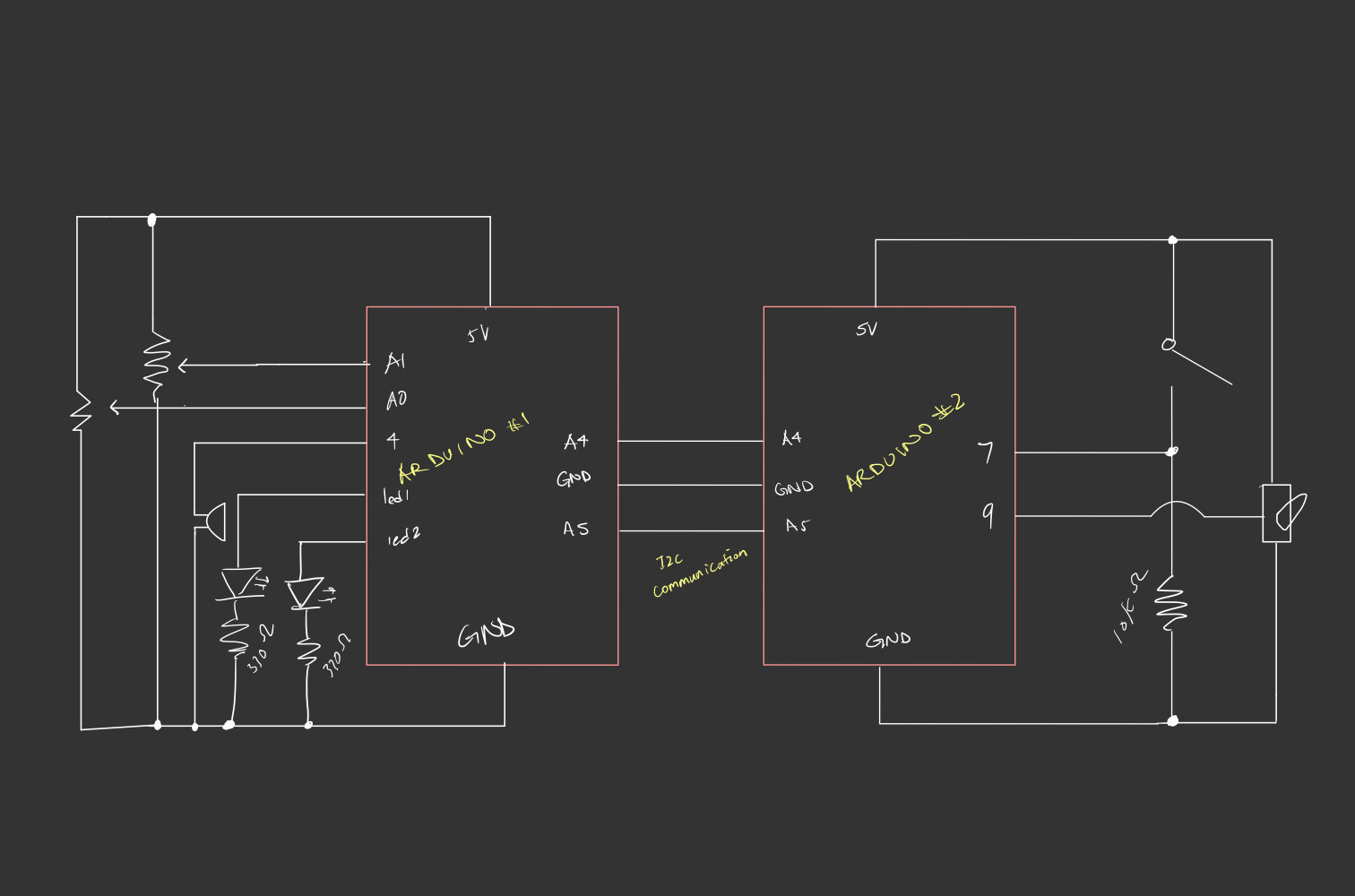
Effectively, the DJ set plays a sequence of notes in succession, stored in a global 2D array, whose pitch class and the tempo of the beat are controlled by the potentiometers. In switching successively between tempos and pitch classes, the player generates different tunes and overall musical moods. The player can also switch on the servo motor, whose position incrementally increases at the same rate set by the tempo the player chose. We utilize two Arduinos, one controlling the sound manipulation between different tempos and pitches using the potentiometers (as well as the LED) and the other controlling the servo motor via a switch. The first Arduino sender program sends the position of the servo motor at time intervals corresponding to the current rate set by the tempo, using the Inter-Integrated Circuit (I2C) Protocol, over to the second Arduino. The receiver program on the second Arduino receives the position and updates the location of the servo, conditional on the button state being on. As the first receiver program also needed to synchronize sound with the blinking of the LEDs, it was essential to extrapolate the concept of blinking without delay to the playing of tones by the buzzer.
Code Snippets
The sender Arduino program sets up a connection using the Wire library in the setup().
void setup() {
  pinMode(led0, OUTPUT);
  pinMode(led1, OUTPUT);
  Wire.begin(); // set up I2C communication
  Serial.begin(9600);
}
The sender Arduino program reads the two potentiometer values, using the first value to control the pitch (by mapping the value to the range 0-3, corresponding to the range of sequences in the global notes array ) and the second to control the tempo/rate of playing a note. The first value is used to index the 2D array,notes[][], which stores the sequence of notes in different pitches. It also sets the brightness of the yellow LED. The second is used to index the duration[] array, which specifies the rate at which notes are played. The notes in the array notes[potVal1] are played in succession, with the next note in the sequence playing if the specified duration has passed. The state of the red LED is updated to blink according to the rate of the current melody being played. Finally, the position of the servo motor is also updated and sent to the second Arduino program.
void loop() {
  // get potentiometer values
  int potVal1 = map(analogRead(potPin1), 0, 1023, 0, 3); // control pitch
  int potVal2 = map(analogRead(potPin2), 0, 1023, 0, 3); // control tempo

  // map the first potentiometer's value to the range [30,255] to control the brightness of the
  // yellow LED - higher pitch -> higher brghtness
  int led0Val = map(constrain(analogRead(potPin1), 30,1023), 0, 1023, 30, 255);
  analogWrite(led0, led0Val); // write the mapped potentiometer value to the LED pin


  // get the duration (based on tempo) from the second potentiomenter
  int duration = durations[potVal2];

  // check if time has elapsed since the last tone
  if (millis() - prevMillis >= duration * 1.60){
    prevMillis = millis(); // update previous time
    led1State = !led1State; // update blinking state for the red LED
    digitalWrite(led1, led1State);
    tone(4, notes[potVal1][note], duration); // play tone that corresponds to the set frequency of the first potentiometer and for the duration set by the second potentiometer

    note++; // cycle through the sequence
    if (note >= 5) {
      note = 0; // Reset note index
    }

    // direction goes forward if position is at 0
    if (position <= 0){
      servoDir = 1;
    }

    // direction goes backward if position is at 160
    else if (position >= 160){
      servoDir = -1;
    }

    position = (position+servoDir*20)%180;
    Wire.beginTransmission(8); // begin transmission to receiver
    Wire.write(position);  // send over the positon of the servo motor
    Wire.endTransmission();    // stop transmitting
    Wire.requestFrom(8, 6);    // request 6 bytes from receiver device #8
    delay(1);
  }

}
The receiver Arduino program receives the position from the sender and updates the position if the switch state is set to 1 (the switch has been pressed to turn on the motor). Since the transmission occurs at a rate equivalent to the rate of the music, the motor will move according to the current tempo of the beat.
#include <Servo.h>
#include <Wire.h>

Servo servo; // initialize servo
int x = 0; // variable storing data transmission
int position = 0; // position of the servo motor

const int switchPin = 7; // switch pin
int buttonState = 0; // current button state
int prevButtonState=0; // previous button state
bool servoMove = false; // keeps track of the switch state

void setup() {
  Serial.begin(9600);
  pinMode(switchPin, INPUT);
  servo.attach(9);
  Wire.begin(8);
  Wire.onReceive(receiveEvent); // initialize event triggered on receipt of data
  Wire.onRequest(requestEvent); // initialize event on being requested data
}

void receiveEvent(int bytes) {
  x = Wire.read();
  // validate received data
  if (x >= 0 && x <= 180) {
    position = x; // x directly maps to servo position
  }
}

void requestEvent()
{
  Wire.write("Hello ");
}

void loop() {
  buttonState = digitalRead(switchPin);

  // maintain the state of the switch and use to determine if the motor should move
  if (buttonState == HIGH && prevButtonState == LOW){
    servoMove = !servoMove;
  };

  // smoothly move the servo towards the desired position
  if (servoMove){
    if (position != servo.read()) {
      if (position > servo.read()) {
        servo.write(servo.read() + 1);
      } else {
        servo.write(servo.read() - 1);
      }
      delay(1);
    };
  }

  prevButtonState = buttonState;
}
Circuit Schematic
Here’s a schematic of our circuitry:
Demo
Reflections and Challenges
One of the things we struggled with, largely due to both of us lacking knowledge of musical compositions, is choosing the right sequence of tones that generate a coherent melody. With a combination of trial and error and some research, we found a suitable sequence. We also faced the challenge of one of our LED lights not turning on when we wired the servo motor to the same circuit. Instead of adding a second power source to connect the servo motor to, we opted to utilize I2C since we had an additional Arduino, which proved to be a useful exercise. Overall, we were happy with the final product, but I think it would be nice to extend this project further and give the player a little more creative control as the current setup is quite restrictive in terms of what final melodies the player can generate. For instance, we can have additional buzzers, each producing a different tone, controlled by switches that the users can use to make their own tunes from scratch over a set beat (something like a MIDI controller? ) .
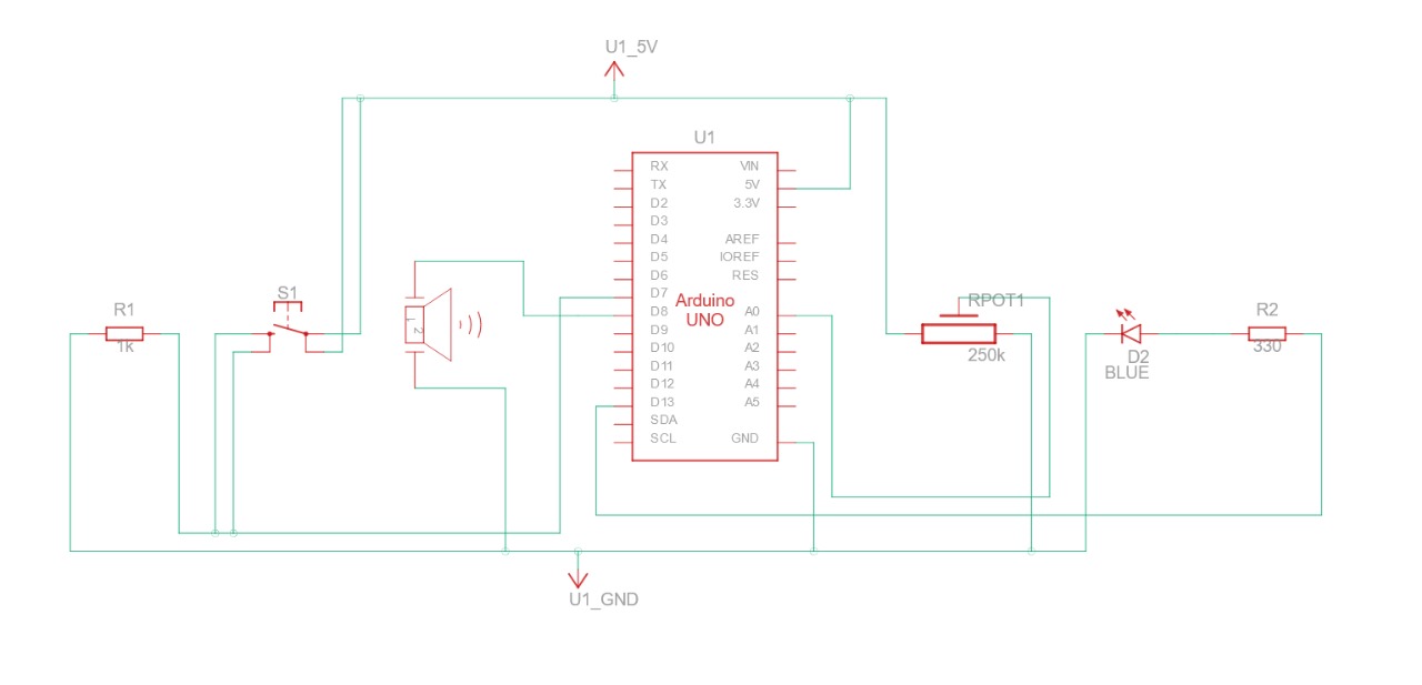
Push the button, it screams. Turn the knob, and it screams even louder. For this week, we decided to create a sound/musical instrument that is controlled by a button and potentiometer.
Concept
We decided to call our machine “Mr.Problematico” because of the issues we encountered while building this machine. The premise is simple: We have a potentiometer that controls the pitch and a button that plays/stops the music.
Demo & Schematics
How it works
In the code, we mapped the potentiometer to 20 different notes. Then, we created an if-else statement, which plays a music function playMusic, whenever the button is pressed and does not play the music whenever it is not pressed.
In the music function, we played the note based on the value received by the potentiometer (value) and turned on the light as well.
 // Map the potentiomenter values according to the list length.
  int note = map(pontValue, 0, 1023, 1, 21);

  // If button is pressed, then play a sound according to the potentiometer.
  if (buttonState == HIGH) {
    playMusic(note);
    //Serial.print("HIGH \n");
  }

  else if (buttonState == LOW) {
    //Serial.print("LOW \n");
  }
}

//Play the tune, wait a specific time and light the LED according to the
//arrays of melodies and duration. In other words, the LED and the sounds generated are synchronized.

void playMusic(int value) {
  int noteDuration = 1000 / noteDurations[value];
  digitalWrite(13, HIGH);
  tone(8, melody[value], noteDuration);
  digitalWrite(13, LOW);
  delay(noteDuration);
}
Closing Remarks
During our building time, we spent a lot of hours trying to figure out why our machine decided to stop very long when we executed the music function. After some consultation, the delay function delays the whole machine rather than the code line. We tried to play and go around trying to fix this weird delay. We figured out that by missing a resistor to the button that messed up the whole circuit, before eventually creating the machine above. It was not completely the code’s fault but rather our miss information.
We’re quite proud of this project. Looking forward to the final project!.
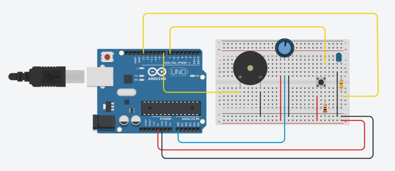
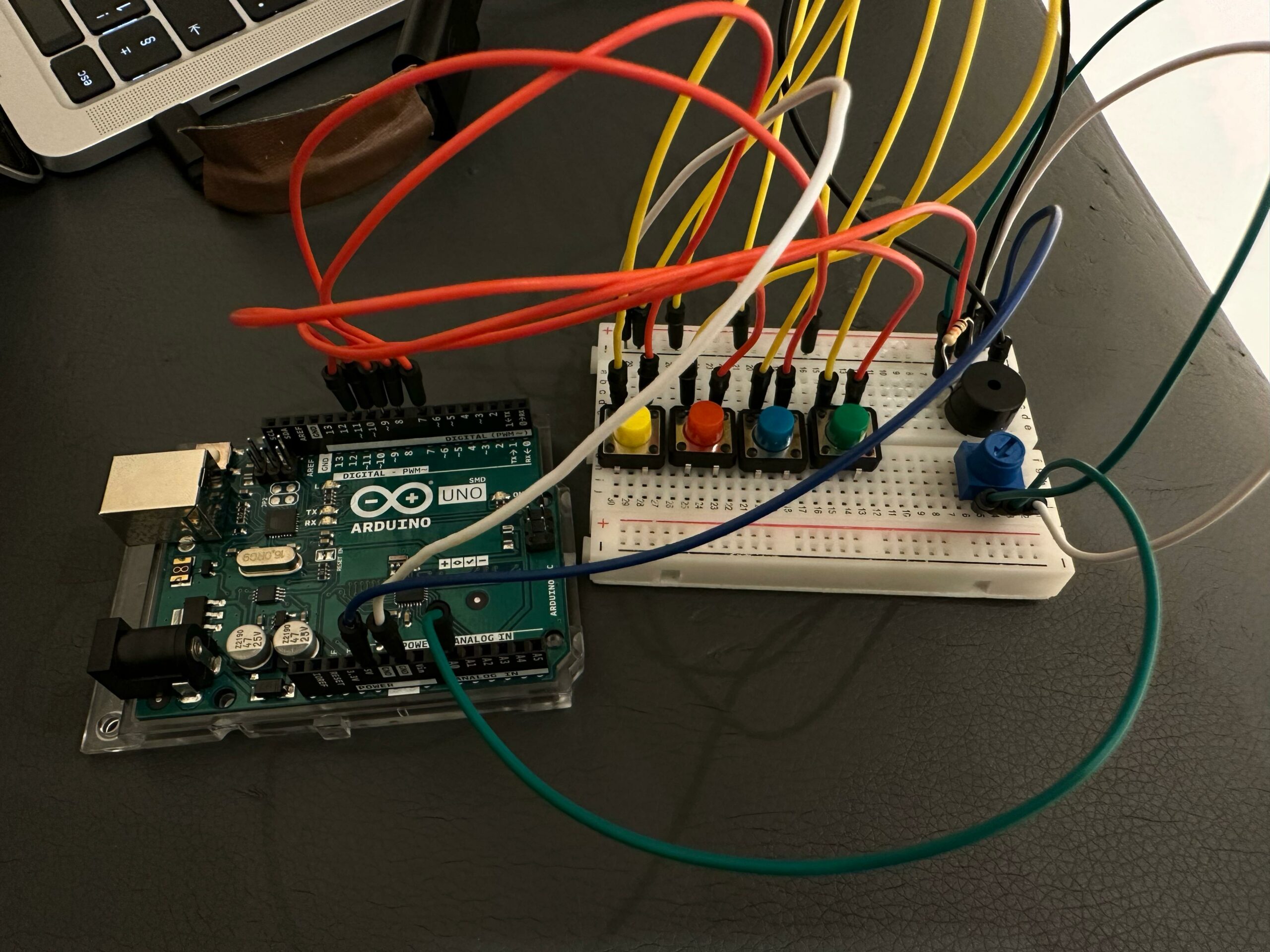
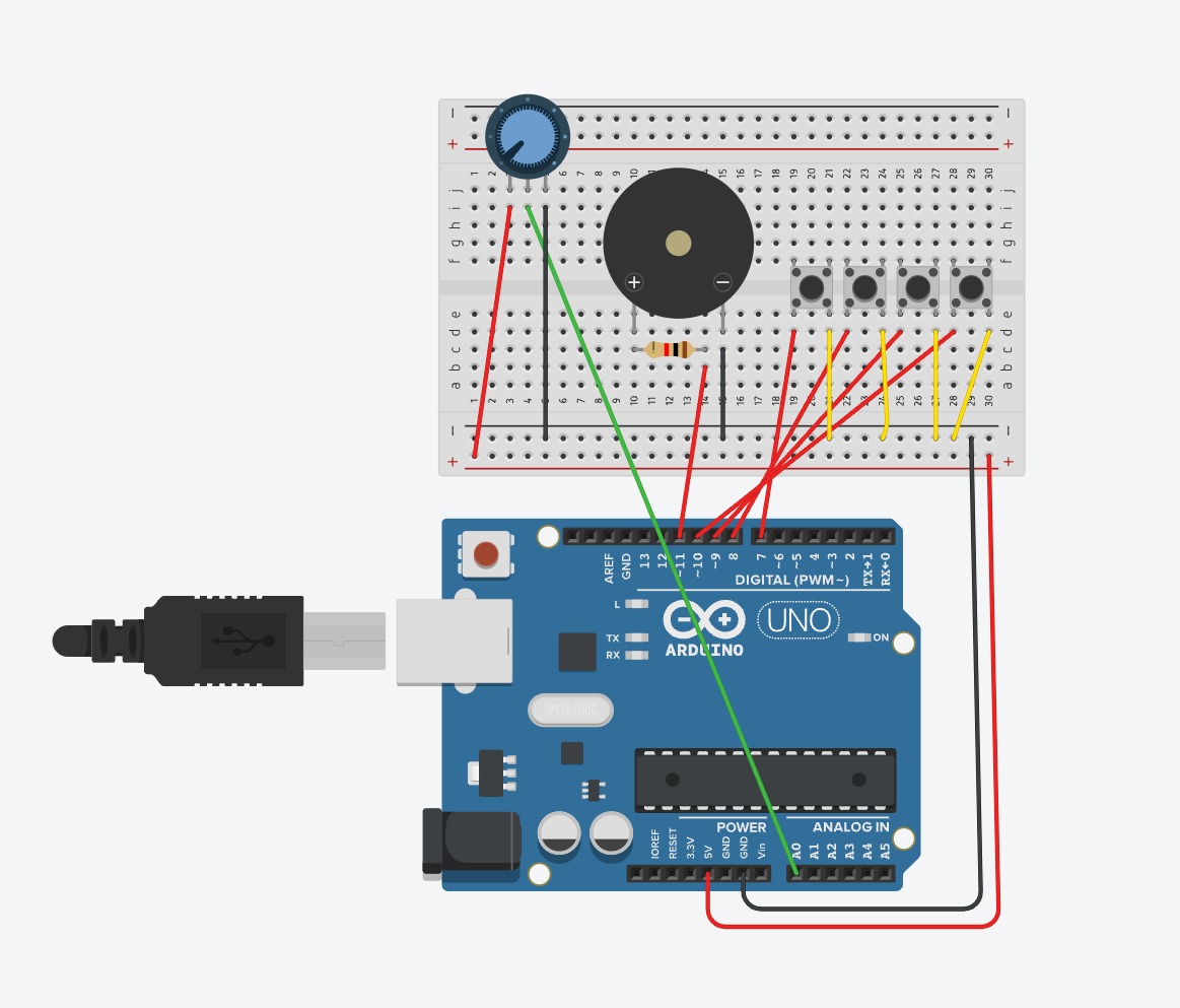
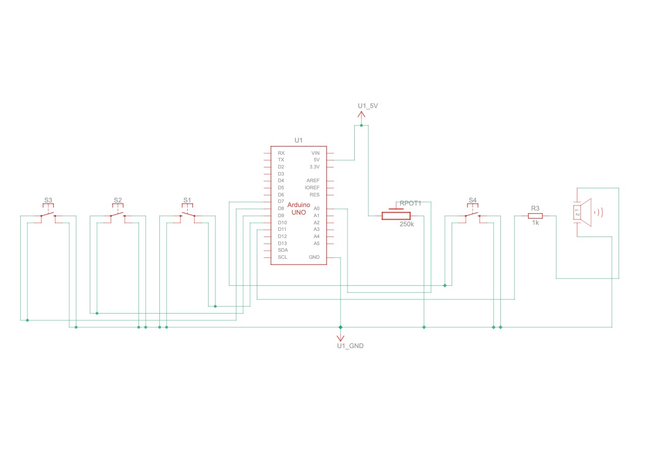
For our assignment, we’ve decided to create a musical instrument, and we settled on making a piano with four keys. Each key, when pressed, will produce a different tone. Our circuit is straightforward, utilizing four push buttons and a buzzer. However, we’ve added an extra component: a potentiometer. This potentiometer allows us to change the frequency of the tones produced by the buzzer. By turning the potentiometer, we can adjust the pitch of the notes, adding more flexibility and range to our piano.
Video Demonstration
Materials we used
Arduino Uno board
Breadboard
330-ohm resistor
4x Tactile push-button switch
Potentiometer
Jumper wires
Piezo buzzer
TinkerCad Diagram
Code
#include <Tone.h>

// Define the notes with more distinguishable frequencies.
#define NOTE_C 262 // Middle C (C4)
#define NOTE_G 392 // G above Middle C (G4)
#define NOTE_C_HIGH 523 // One octave above Middle C (C5)
#define NOTE_G_HIGH 784 // G above C5 (G5)

#define ACTIVATED LOW

const int PIEZO = 11;
const int LED = 13;

const int BUTTON_C = 10;  // Will play Middle C
const int BUTTON_D = 9;   // Will play G (above Middle C)
const int BUTTON_E = 8;   // Will play High C
const int BUTTON_F = 7;   // Will play High G

const int POTENTIOMETER = A0; // Analog input pin connected to the potentiometer

Tone toneGenerator;

void setup() {
  pinMode(LED, OUTPUT);

  pinMode(BUTTON_C, INPUT_PULLUP);
  pinMode(BUTTON_D, INPUT_PULLUP);
  pinMode(BUTTON_E, INPUT_PULLUP);
  pinMode(BUTTON_F, INPUT_PULLUP);

  toneGenerator.begin(PIEZO);
  digitalWrite(LED, LOW);
}

void loop() {
  int potValue = analogRead(POTENTIOMETER); // Read the potentiometer value
  int frequencyAdjustment = map(potValue, 0, 1023, 0, 255); // Map to a quarter of the full range for adjustment

  if (digitalRead(BUTTON_C) == ACTIVATED) {
    toneGenerator.play(NOTE_C + frequencyAdjustment); // Adjust Middle C frequency
    digitalWrite(LED, HIGH);
  } else if (digitalRead(BUTTON_D) == ACTIVATED) {
    toneGenerator.play(NOTE_G + frequencyAdjustment); // Adjust G frequency
    digitalWrite(LED, HIGH);
  } else if (digitalRead(BUTTON_E) == ACTIVATED) {
    toneGenerator.play(NOTE_C_HIGH + frequencyAdjustment); // Adjust High C frequency
    digitalWrite(LED, HIGH);
  } else if (digitalRead(BUTTON_F) == ACTIVATED) {
    toneGenerator.play(NOTE_G_HIGH + frequencyAdjustment); // Adjust High G frequency
    digitalWrite(LED, HIGH);
  } else {
    toneGenerator.stop();
    digitalWrite(LED, LOW);
  }
}
Functionality
Upon pressing a button, the Arduino reads which button is pressed and plays a specific tone. The potentiometer’s position adjusts the base frequency of this tone, making the sound higher or lower based on its rotation.
The piano uses the Arduino’s built-in “tone” library to handle tone generation, which simplifies the creation of audible frequencies through digital pins.
Future Improvements
For future improvements we would like to:
Enhance the clarity and volume of the piano’s notes.
Add more keys and different types of tones to the piano.
Integrate LEDs to make it look more attractive and visually appealing.