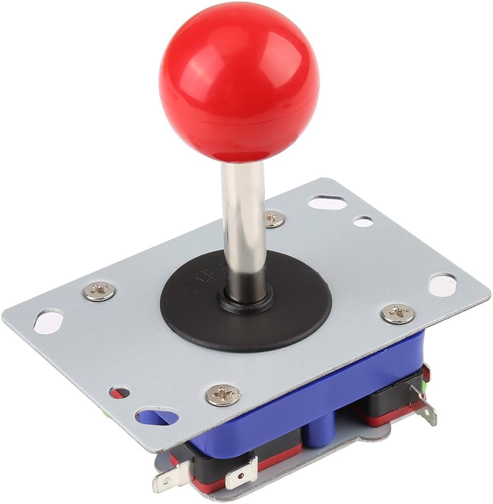
The project’s primary goal is to design and construct a custom joystick game controller using Arduino. This controller will enhance player interaction with a browser-based video game developed in p5.js, offering a more intuitive and engaging gameplay experience compared to standard keyboard or mouse controls.
Controller Features:
Joystick for Directional Control:
The joystick will allow players to control movement within the game with greater precision and fluidity. It will capture analog input to provide a smoother response compared to digital keys.
Tactile Feedback Buttons:
Additional buttons will be incorporated for game-specific actions (e.g., jumping, shooting). These will use tactile switches to give a satisfying click feel, ensuring immediate and comfortable response.
Vibration Feedback:
Incorporate vibration motors that activate during specific game events, such as collisions or other significant interactions, to provide physical feedback that enhances the immersion.
LED Feedback System:
LEDs will be programmed to react to different situations in the game, such as game alerts, low health, or achievement notifications, adding another layer of feedback and interaction.
Technical Components:
Arduino Board: Acts as the central processing unit for the joystick controller, reading inputs from the joystick and buttons, and managing outputs like LED indicators and vibration motors.
Analog Joystick Module: Captures detailed directional inputs from the player, translating them into game movements.
Vibration Motors: To provide immediate tactile feedback during critical game events, enhancing the physical experience of the gameplay
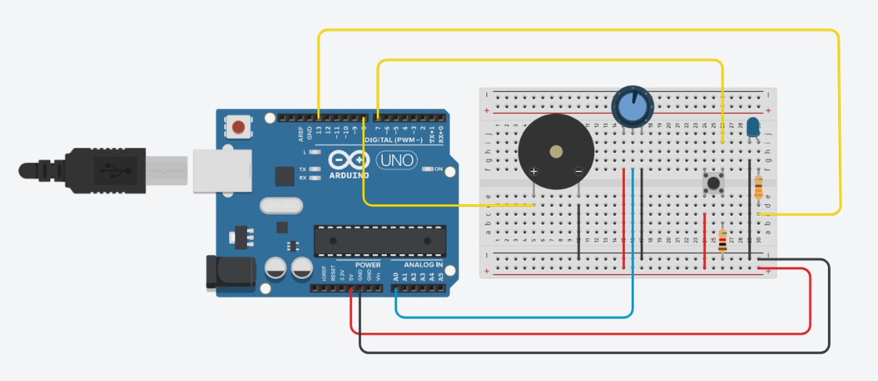
The concept of this project was to create a mini drum pad, or what is equivalent to one, with the hardware we have available. The device would use buttons to trigger different buzzer sounds, mimicking the functionality of a traditional drum pad. Each button on the device would correspond to a different sound, with the frequency of these sounds adjustable via a potentiometer. This allows the user to modify the pitch of the tones.
Code:
// Defining pins assignments for buttons and buzzers
const int buttonPin1 = 2;
const int buttonPin2 = 3;
const int buttonPin3 = 4;
// Coded with the Aid of ChatGPT
const int buttonPin4 = 5; // Monitoring and playbacks button
// Coded with the Aid of ChatGPT
const int buzzerPin1 = 8;
const int buzzerPin2 = 9;
const int buzzerPin3 = 10;
const int potPin = A0; // Potentiometer connected to A0 for frequency control

// Variables to manage button states and debounce timing
int buttonState1 = 0;
int lastButtonState1 = 0;
int buttonState2 = 0;
int lastButtonState2 = 0;
int buttonState3 = 0;
int lastButtonState3 = 0;
int buttonState4 = 0;
int lastButtonState4 = 0;

unsigned long lastDebounceTime1 = 0;
unsigned long lastDebounceTime2 = 0;
unsigned long lastDebounceTime3 = 0;
unsigned long lastDebounceTime4 = 0;
unsigned long debounceDelay = 50; // Debounce delay in milliseconds

// Struct to hold buzzer activation data including the pin and frequency
struct BuzzerAction {
  int buzzerPin;
  int frequency;
};

// Coded with the Aid of ChatGPT
BuzzerAction record[100]; // Array to store each buzzer activation
int recordIndex = 0; // Index for recording array
//Coded with the Aid of ChatGPT

void setup() {
  // Initialize all button and buzzer pins
  pinMode(buttonPin1, INPUT);
  pinMode(buttonPin2, INPUT);
  pinMode(buttonPin3, INPUT);
// Coded with the Aid of ChatGPT
  pinMode(buttonPin4, INPUT);
// Coded with the Aid of ChatGPT
  pinMode(buzzerPin1, OUTPUT);
  pinMode(buzzerPin2, OUTPUT);
  pinMode(buzzerPin3, OUTPUT);
  pinMode(potPin, INPUT); // Setups potentiometer pin as input
}

void loop() {
  // Reads current state of buttons
  int reading1 = digitalRead(buttonPin1);
  int reading2 = digitalRead(buttonPin2);
  int reading3 = digitalRead(buttonPin3);
// Coded with the Aid of ChatGPT
  int reading4 = digitalRead(buttonPin4);
// Coded with the Aid of ChatGPT
  int potValue = analogRead(potPin); // Reads potentiometer value
  int frequency = map(potValue, 0, 1023, 200, 2000); // Maps potentiometer value to frequency range

  // Handle button 1 press and recording
  debounceAndRecord(reading1, &lastButtonState1, &buttonState1, &lastDebounceTime1, buzzerPin1, frequency);

  // Handle button 2 press and recording
  debounceAndRecord(reading2, &lastButtonState2, &buttonState2, &lastDebounceTime2, buzzerPin2, frequency);

  // Handle button 3 press and recording
  debounceAndRecord(reading3, &lastButtonState3, &buttonState3, &lastDebounceTime3, buzzerPin3, frequency);

  // Handles button 4 for playback
  if (reading4 != lastButtonState4) {
    lastDebounceTime4 = millis();
  }
  if ((millis() - lastDebounceTime4) > debounceDelay) {
    if (reading4 != buttonState4) {
      buttonState4 = reading4;
      if (buttonState4 == HIGH) {
        for (int i = 0; i < recordIndex; i++) {
          // Play each recorded buzzer action with the specific frequency recorded
          tone(record[i].buzzerPin, record[i].frequency, 200);
          delay(250); // Short delay between each buzzer action for clarity
        }
        recordIndex = 0; // Resets record index after playback
      }
    }
  }

  // Update last button states for next loop iteration
  lastButtonState1 = reading1;
  lastButtonState2 = reading2;
  lastButtonState3 = reading3;
  lastButtonState4 = reading4;
}
// Coded with the Aid of ChatGPT
// Function to handle button debouncing and recording buzzer actions
void debounceAndRecord(int reading, int *lastButtonState, int *buttonState, unsigned long *lastDebounceTime, int buzzerPin, int frequency) {
  if (reading != *lastButtonState) {
    *lastDebounceTime = millis(); // Reset debounce timer
  }
  if ((millis() - *lastDebounceTime) > debounceDelay) {
    if (reading != *buttonState) {
      *buttonState = reading; // Updates button state
      if (*buttonState == HIGH && recordIndex < sizeof(record) / sizeof(record[0])) {
        record[recordIndex++] = {buzzerPin, frequency}; // Records the buzzer activation
        tone(buzzerPin, frequency, 200); // Plays buzzer at recorded frequency
      }
    }
  }
  *lastButtonState = reading; // Updates last button state for debouncing
// Coded with the Aid of ChatGPT
}
Hardware Configuration: The system is designed with four button inputs and three buzzer outputs. Additionally, a potentiometer is used to control the frequency of the buzzer sounds.
Button Functionality: Buttons 1 to 3 are connected to buzzers and are responsible for triggering sounds with variable frequencies determined by the potentiometer. Button 4 is designated for playback. It plays back a sequence of sounds that have been recorded based on earlier interactions with buttons 1 to 3.
Frequency Control: The frequency of the sounds is dynamically adjusted using a potentiometer. The analog value from the potentiometer is mapped to a specified frequency range (200 Hz to 2000 Hz), which determines how the buzzers sound.
Debouncing: To ensure reliable button press detection without noise interference, the code implements debouncing logic. This involves measuring the time since the last button state change and updating the state only if this interval exceeds a predefined threshold (50 milliseconds).
Recording and Playback (Aided by Chatgpt)
Recording: When a button (1 to 3) is pressed, the action (which buzzer is activated and at what frequency) is recorded in an array. This includes storing both the pin of the buzzer and the frequency at which it was activated.
Playback: When button 4 is pressed, the system iterates over the recorded actions and plays them sequentially. Each action triggers the corresponding buzzer to sound at the recorded frequency for a short duration.
Loop and Functions : The main loop continuously checks the state of each button and the potentiometer, updating the frequency accordingly. A helper function, debounceAndRecord, is used to handle the logic for both debouncing and recording the buzzer actions associated with each button press.
Video of Project:
Reflection and ideas for future work or improvements:
Integrating a small display screen would significantly improve its functionality, further enhancing the project. This screen would provide real-time visual feedback on button presses and frequency outputs, allow users to scroll through and select different sounds or presets, and serve as a simple interface for directly programming the device. The potential for further development and refinement holds exciting prospects. The integration of a display screen and the addition of more customizable buttons are immediate steps that will enhance the device’s usability and versatility. Further innovations could include wireless connectivity for easy integration with other music production software or the addition of sensors
to enable gesture-based controls, which would offer an even more dynamic and immersive user experience. Several key insights stand out after reflecting on what this project has taught us. First, the practical challenges of hardware interfacing taught us the importance of robust design and a
solid plan for creating it. There is also a need for effective wire management and physical housing to enhance device durability and aesthetics.
For the final project, I am quite conflicted between the following two ideas: A platformer that uses light to move platforms or a Wario Ware like game which uses as much of the interactive mediums from Arduino as possible.
A platformer that uses light to move platforms
This project would be inspired by the simple mechanics of a platformer game like Super Mario Bros., but the difference is that, aside from only walking, the player possesses the power to interact with platforms through the use of light. This would be possible with the use of a photoresistor.
The game would consist of a set of three levels in P5, with the player only having three lives through the whole session. As for the controls, it would use a pair of two buttons to control the movement while a dedicated flashlight, that is close, is going to assist in moving the platforms. The platforms will have a set axis to move, and although simple and monotonous, obstacles such as flying bullets or damaging movable obstacles can also be included.
Figure #1 Image used for reference regarding the flashlight (Englishscone, 2018).
A Wario Ware like game using Arduino
Wario Ware is a video game developed by Nintendo that debuted in 2003. It presents a series of video games which include moving an umbrella to make sure a cat does not get wet to shaking the hand of a dog. All of this is done through the use of the characteristic touch screen capabilities of a Nintendo device. Therefore, the approach to this game using Arduino would be to randomize the set of minigames and prepare all the needed inputs in the Arduino devices.
For example, in P5, if a minigame requires that the player presses the button 10 times quickly, the player has to do so in the button that is near the Arduino. The other scenario as well is if the player needs to turn off the light in the minigame, which in this case would be done by covering the photoresistor.
The issue itself in this game would lie in how to convey rapidly what kind of input does the game want, as well as providing the Arduino input controls attractively.
Figure #2 Some of the minigames presented in Wario Ware (Nintendo, 2003-Present day).
Conclusion
As always, all of these ideas will possibly change. Nevertheless, if this is given the time to properly experiment on the possibility of completing the selected project, then there is a guaranteed level of success only if ambitions are controlled and the video game is iterated multiple times.
The readings provided for this week gives an interesting reflection on the current state of Interaction Design and what lies ahead. Contrary to the rant given by the author, I do believe (at least in a sense) that technologies that follows the design of “Picture under glass” can be both helpful and intuitive, but when used something else is lost: The human feedback.
In my daily life, the only touchscreen-based device that I use exclusively is my iPhone. The rest is through other physical mediums, such as keyboards and mouse. The key difference in them is that some can provide a greater level of feedback than the other, while still providing giving the same function. A book in a iPad is still going to display what I want to read, but the smell, the feel, the weight, and the feeling of possession are lost.
It is a bit sad how we are also seeing our society shift from a more human feedback to what it seems to be more robotic and productive. Take into consideration Microsoft’s “Productivity Future Vision”, a future where productivity reigns over the interactional design that fills the human being with the necessary non-visual feedback that tells the current state of the object. Regardless of this. Nevertheless, by raising awareness (as the author indicates) we can make sure that we still value projects that aim for the user to be more in touch with the inner-self; in control through the use of sensory cues other than the sense that one gets from touching a glass touch.
The Brief Rant is a thought out argument for changing our perspective towards our current approach to interaction design and calling the need for other mediums. It focuses on the limits of our current technology and the implications it has on us.
The analogy between kid’s book depriving adults of the complexity of english vocab same goes to touchscreens to restricting interaction design and our capabilities.
In considering another real-world example, my mind goes to VR and AR. Although these technologies have advanced considerably in the past couple of years, there’s still lots of room for growth in terms of interaction design. Picture this: VR systems could undergo enhancement with haptic feedback technology, where it would enbale more immersion.
The other reading also highlights how adeptly we use our hands in everyday tasks, like opening jars and making sandwiches, contrasting this natural interaction with the detached experience of using flat screens. It questions why we settle for interfaces that don’t harness the richness of human touch and manipulation. The author is calling for a interactive design movement that I do see coming in the next couple years hopefully!
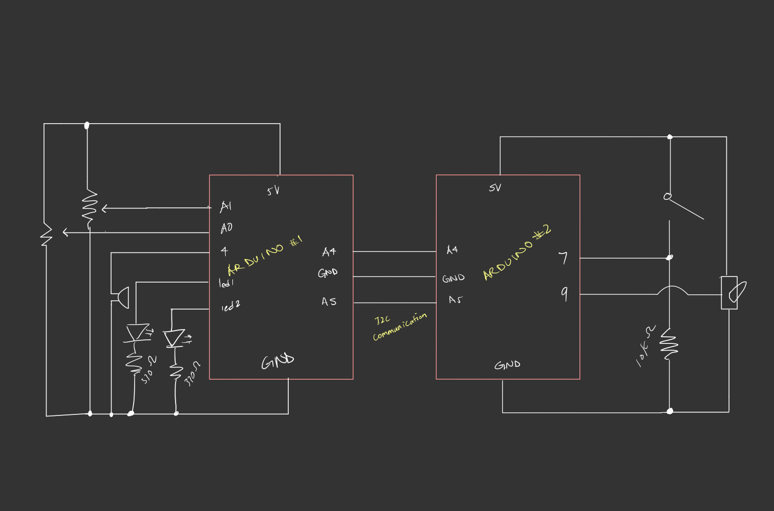
For this week’s assignment Sarah and I created a DJ set! The set is built using two potentiometers, a digital switch, a piezo buzzer, servo motors, and two LEDs (for visual feedback). When connected to power, the set produces a melody that the player (DJ) can manipulate by using the first potentiometer (which controls the pitch) and the second potentiometer (which controls the tempo). The red LED blinks in sync with the tempo set by the second potentiometer. The yellow LED’s brightness is proportional to the pitch (the higher the pitch, the higher the brightness). The servo motor resembles the turntables on an actual DJ set. You can activate it by pressing the digital switch. Upon activation, the servo motor will rotate at a speed equivalent to the beat’s tempo.
Implementation
Effectively, the DJ set plays a sequence of notes in succession, stored in a global 2D array, whose pitch class and the tempo of the beat are controlled by the potentiometers. In switching successively between tempos and pitch classes, the player generates different tunes and overall musical moods. The player can also switch on the servo motor, whose position incrementally increases at the same rate set by the tempo the player chose. We utilize two Arduinos, one controlling the sound manipulation between different tempos and pitches using the potentiometers (as well as the LED) and the other controlling the servo motor via a switch. The first Arduino sender program sends the position of the servo motor at time intervals corresponding to the current rate set by the tempo, using the Inter-Integrated Circuit (I2C) Protocol, over to the second Arduino. The receiver program on the second Arduino receives the position and updates the location of the servo, conditional on the button state being on. As the first receiver program also needed to synchronize sound with the blinking of the LEDs, it was essential to extrapolate the concept of blinking without delay to the playing of tones by the buzzer.
Code Snippets
The sender Arduino program reads the two potentiometer values, using the first value to control the pitch (by mapping the value to the range 0-3, corresponding to the range of sequences in the global notes array ) and the second to control the tempo/rate of playing a note. The first value is used to index the 2D array, notes[][], which stores the sequence of notes in different pitches. It also sets the brightness of the yellow LED. The second is used to index the duration[] array, which specifies the rate at which notes are played. The notes in the array notes[potVal1] are played in succession, with the next note in the sequence playing if the specified duration has passed. The state of the red LED is updated to blink according to the rate of the current melody being played. Finally, the position of the servo motor is also updated and sent to the second Arduino program.
note++; // cycle through the sequence
if (note >= 5) {
note = 0; // Reset note index
}
// direction goes forward if position is at 0
if (position <= 0){
servoDir = 1;
}
// direction goes backward if position is at 160
else if (position >= 160){
servoDir = -1;
}
position = (position+servoDir*20)%180;
Wire.beginTransmission(8); // begin transmission to receiver
Wire.write(position); // send over the positon of the servo motor
Wire.endTransmission(); // stop transmitting
Wire.requestFrom(8, 6); // request 6 bytes from receiver device #8
delay(1);
}
}
The receiver Arduino program receives the position from the sender and updates the position if the switch state is set to 1 (the switch has been pressed to turn on the motor). Since the transmission occurs at a rate equivalent to the rate of the music, the motor will move according to the current tempo of the beat.
#include
#include
Servo servo; // initialize servo
int x = 0; // variable storing data transmission
int position = 0; // position of the servo motor
const int switchPin = 7; // switch pin
int buttonState = 0; // current button state
int prevButtonState=0; // previous button state
bool servoMove = false; // keeps track of the switch state
void setup() {
Serial.begin(9600);
pinMode(switchPin, INPUT);
servo.attach(9);
Wire.begin(8);
Wire.onReceive(receiveEvent); // initialize event triggered on receipt of data
Wire.onRequest(requestEvent); // initialize event on being requested data
}
void receiveEvent(int bytes) {
x = Wire.read();
// validate received data
if (x >= 0 && x <= 180) {
position = x; // x directly maps to servo position
}
}
void requestEvent()
{
Wire.write("Hello ");
}
void loop() {
buttonState = digitalRead(switchPin);
// maintain the state of the switch and use to determine if the motor should move
if (buttonState == HIGH && prevButtonState == LOW){
servoMove = !servoMove;
};
// smoothly move the servo towards the desired position
if (servoMove){
if (position != servo.read()) {
if (position > servo.read()) {
servo.write(servo.read() + 1);
} else {
servo.write(servo.read() - 1);
}
delay(1);
};
}
prevButtonState = buttonState;
}
Circuit Schematic
Here’s a schematic of our circuitry: Have a look:
Reflections and Challenges
One of the things we struggled with, largely due to both of us lacking knowledge of musical compositions, is choosing the right sequence of tones that generate a coherent melody. With a combination of trial and error and some research, we found a suitable sequence. We also faced the challenge of one of our LED lights not turning on when we wired the servo motor to the same circuit. Instead of adding a second power source to connect the servo motor to, we opted to utilize I2C since we had an additional Arduino, which proved to be a useful exercise. Overall, we were happy with the final product, but I think it would be nice to extend this project further and give the player a little more creative control as the current setup is quite restrictive in terms of what final melodies the player can generate. For instance, we can have additional buzzers, each producing a different tone, controlled by switches that the users can use to make their own tunes from scratch over a set beat (something like a MIDI controller? ) .
For my final project, I am thinking of making a game where players are presented with a series of electronic puzzles that increase in complexity.
Each puzzle requires players to assemble components on a breadboard within a set time limit. The game provides immediate feedback on their solutions, and players earn points based on speed and accuracy.
Arduino
Breadboard where players will plug in various electronic components like resistors, wires, buzzers, or other sensors.
I would require some kind of sensors that would verify whether components are correctly placed and circuits are properly completed on the breadboard.
If Possible
Optionally, include buttons or switches on the board for starting the timer, resetting the puzzle, or requesting hints.
Processing
Processing will display each puzzle diagram on a screen, track the time remaining, and handle the transition between different puzzles.
Immediately inform players whether the circuit is correct. If incorrect, highlight errors or provide hints, depending on the game mode.
A scoring algorithm based on the complexity of the puzzle, the accuracy of the completed circuit, and the speed of completion.
Push the button, it screams. Turn the knob, and it screams even louder. For this week, we decided to create a sound/musical instrument that is controlled by a button and potentiometer.
Concept
We decided to call our machine, “Mr.Problematico” because of the issues we encountered while building this machine. The premise is simple: We have a potentiometer that controls the pitch and a button that plays/stops the music.
How it works
In the code, we mapped the potentiometer to 20 different notes. Then, we created an if-else statement, which plays a music function playMusic, whenever the button is pressed and does not play the music whenever it is not pressed.
In the music function, we played the note based on the value received by the potentiometer (value) and turned on the light as well.
 // Map the potentiomenter values according to the list length.
  int note = map(pontValue, 0, 1023, 1, 21);
  // If button is pressed, then play a sound according to the potentiometer.
  if (buttonState == HIGH) {
    playMusic(note);
    //Serial.print("HIGH \n");
  }
  else if (buttonState == LOW) {
    //Serial.print("LOW \n");
  }
}
//Play the tune, wait a specific time and light the LED according to the
//arrays of melodies and duration. In other words, the LED and the sounds generated are synchronized.
void playMusic(int value) {
  int noteDuration = 1000 / noteDurations[value];
  digitalWrite(13, HIGH);
  tone(8, melody[value], noteDuration);
  digitalWrite(13, LOW);
  delay(noteDuration);
}
Closing Remarks
During our building time, we spent a lot of hours trying to figure out why our machine decided to stop very long when we executed the music function. After some consultation, the delay function delays the whole machine rather than the code line. We tried to play and go around trying to fix this weird delay. We figured out that by missing a resistor to the button that messed up the whole circuit, before eventually creating the machine above. It was not completely the code’s fault but rather our miss information.
We’re quite proud of this project. Looking forward to the final project!
For this assignment, we were inspired by the popular “Rick Rolling” meme. Essentially, this is a meme that tricks the viewer by surprisingly playing the song “Never Gonna Give You Up” by Rick Astley. Therefore, we decided to create a music box which plays this song when it’s opened.
How it works
For the music box, we had multiple components. First, we used a photoresistor to detect brightness (open box) and darkness (closed box), which would determine whether to play the song or not. Then, we had a Piezo buzzer to actually play the notes of the song. Moreover, we added a LED light that blinks to the rhythm of the music. We also added a button which when pressed, would change the speed at which the music plays. Finally, we used a potentiometer to control the volume of the music. In the code, we divided the song into the intro, verse, and chorus.
Components
1 x Photoresistor
1 x Piezo buzzer
1 x LED Light
1 x Button
1 x Potentiometer
3 x 330 ohm resistors
1 x 10K ohm resistor
Wires
Arduino and Breadboard
Demo
Code Snippets
Our code is quite long, so here are some snippets:
This is an example of how we have created arrays for each part of the song. This is specifically for the chorus, but we also have them for the intro and the verse. We have one array for the melody, which is determined by the frequencies we have defined, and one for the rhythm, which determines the duration of each note when later multiplied with the beat length.
This is our setup function, which initializes the pins and the serial communication, and sets an interrupt on the button (which then trigger our getFaster function).
void   setup()
{
  pinMode(piezo, OUTPUT);
  pinMode(led, OUTPUT);
  pinMode(button,   INPUT_PULLUP); // high voltage when button is not pressed; low voltage when pressed
  pinMode(sensor, INPUT);
  attachInterrupt(digitalPinToInterrupt(button), getFaster, FALLING); // interrupt activates when pin is pressed
  digitalWrite(led, LOW);
  Serial.begin(9600);
  flag   = false;
  a = 4;
  b = 0;
  threshold = analogRead(sensor) + 200; // adding a value to the sensor reading to control how much darkness/brightness is necessary for the music to start playing
}
This is our loop function, which ensures that the sensor value is constantly being read and that the song plays when it is bright enough/pauses when it is dark.
void loop()
{
  int sensorreading = analogRead(sensor);
   if (sensorreading < threshold) { // play when there is brightness
    flag = true;
  }
   else if (sensorreading > threshold) { // pause when there is darkness
    flag = false;
   }

  // play next step in song when flag is true, meaning it is bright enough
  if (flag == true) {
    play();
   }
}
This is part of our play function, which determines which part of the song plays and the corresponding melody/rhythm.
void play() {
  int notelength;
  if (a == 1 || a == 2) {
     // intro
    notelength = beatlength * song1_intro_rhythmn[b];
    if   (song1_intro_melody[b] > 0) {
      digitalWrite(led, HIGH); // LED on
      tone(piezo,   song1_intro_melody[b], notelength);
    }
    b++;
    if (b >= sizeof(song1_intro_melody)   / sizeof(int)) {
      a++;
      b = 0;
      c = 0;
    }
And finally, our getFaster function to increase tempo by the decreasing the beat length when the button is pressed.
void getFaster()   { // decrease beat length in order to increase tempo
  beatlength = beatlength   / 2;
  if (beatlength < 20) { // loop back to original tempo
    beatlength   = 100;
  }
Circuit
Lastly, here is a link to the tutorial we followed: https://projecthub.arduino.cc/slagestee/rickroll-box-d94733
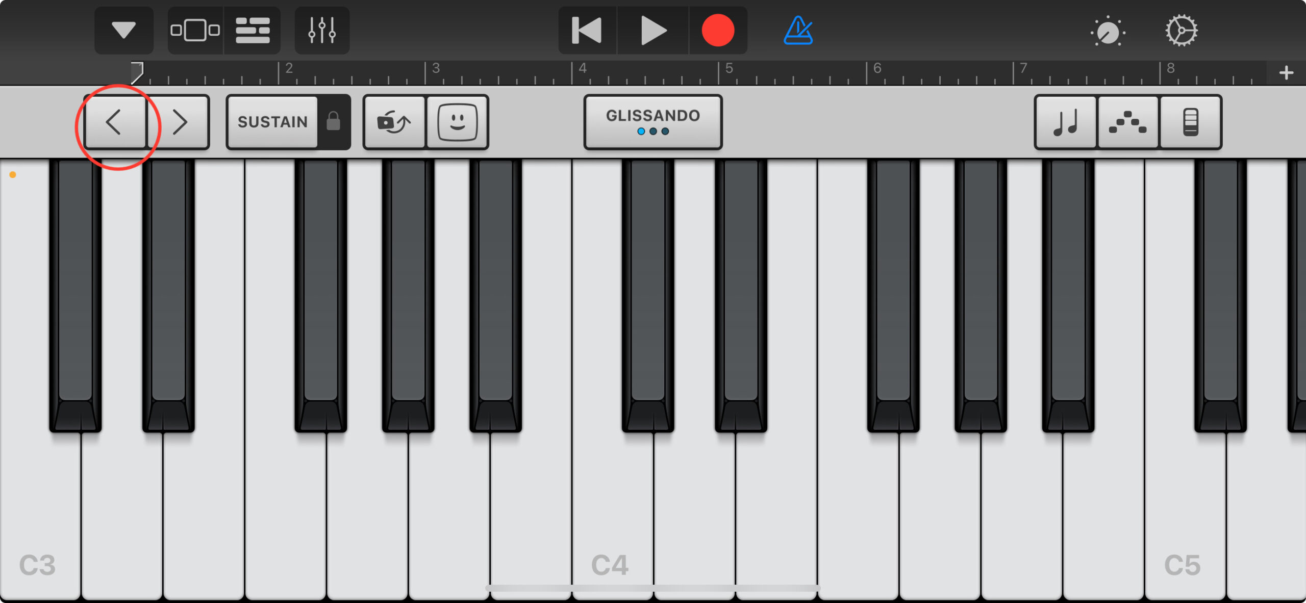
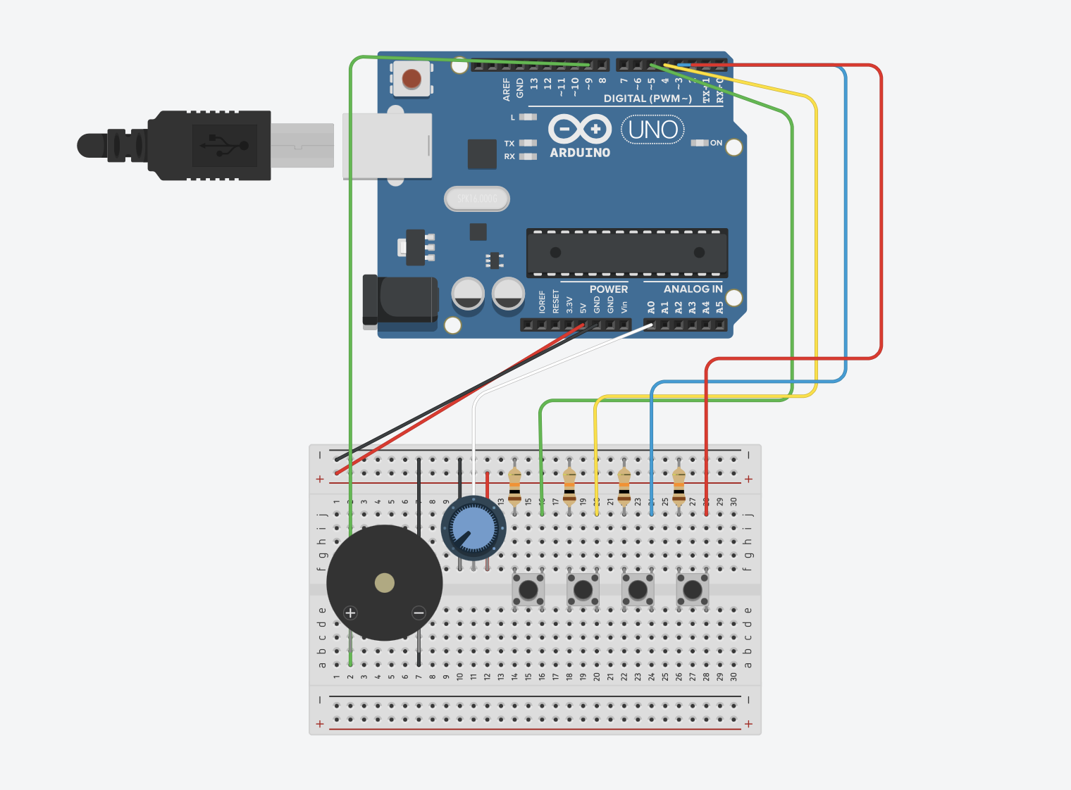
For this assignment, we wanted to go with something simple. Rashed is known for his love for music so I was excited to see what we would come up with. During our brainstorming session, Rashed was doing his hobby – which is music production- on his phone on GarageBand and he noticed how he had to click on the “arrow” button to change the pitch of the piano and we decided we wanted to do something like that but with the potentiometer.
The pitch-changing arrow I was referring to on GarageBand:
Materials used:
x11 Wires
x4 Buttons
x4 10k Resistors
x1 Buzzer
x1 Potentiometer
Production:
Writing this code was pretty challenging for us as both of us are still adapting to this new language.
We used the toneMelody example from the examples folder that we used in class to take the “pitches.h” tab from it in order to give a specific range. We collectively decided to have the buttons, by default, be the most basic notes “Do, Re, Me, Fa” also known as “NOTE_C4, NOTE_D4, NOTE_E4, NOTE_F4” which was pretty simple to implement.
However, we faced one major issue:
For some reason, the potentiometer would not cooperate at all. The buttons were working fine, but the pitch won’t budge. We, unfortunately, had to use ChatGPT to help us but it was still very helpful in helping us understand what we were doing wrong.
Here’s the code:
#include "pitches.h"

const int speakerPin = 9;  // Speaker connected to pin 9
int buttonPins[] = {2, 3, 4, 5};  // Button pins for notes
int potPin = A0;  // Potentiometer connected to A0

// Initialize an array of notes that will be used depending on the button press
int noteIndices[] = {NOTE_C4, NOTE_D4, NOTE_E4, NOTE_F4};  // Starting notes for each button

void setup() {
  for (int i = 0; i < 4; i++) {
    pinMode(buttonPins[i], INPUT_PULLUP);  // Setup button pins as input with pull-up resistor
  }
  pinMode(speakerPin, OUTPUT);  // Set speaker pin as output
}

void loop() {
  int potValue = analogRead(potPin);  // Read the current value from the potentiometer
  int noteRange = NOTE_C6 - NOTE_C4;  // Define the range of notes to span
  int noteOffset = map(potValue, 0, 1023, 0, noteRange);  // Map potentiometer value to note range

  for (int i = 0; i < 4; i++) {
    if (digitalRead(buttonPins[i]) == LOW) {
      int noteToPlay = noteIndices[i] + noteOffset;
      tone(speakerPin, noteToPlay);  // Play the note on the speaker
      delay(200);  // A short delay to help debounce the button
      while (digitalRead(buttonPins[i]) == LOW);  // Wait for button release
      noTone(speakerPin);  // Stop the note
    }
  }
}
Here’s the video where we use it:
Reflection:
I think, despite chatGPT’s involvement in this, we did pretty well; the concept was there, the energy and effort that was put into this is there and we’re both proud of our little creation. However, we both do with we took it a step further and maybe added more buttons or tried to use the sensor instead of the potentiometer. We really hope to get used to and adapt to this language.