Musical Instrument (Nourhane & Aya)

Concept:

Finding a concept for this assignment was complicated. We had a couple of cool ideas at the beginning, like using soda cans as drums, but unfortunately, their implementation didn’t go as planned.  We decided  in the end to use our favorite part of the kit: the ultrasonic sensor, and get a concept out of it.

Both our previous assignments used ultrasonic sensors as distance detectors. So we thought to base this assignment on the same concept.

We were inspired by the Accordion instrument when designing this musical instrument (with a twist):
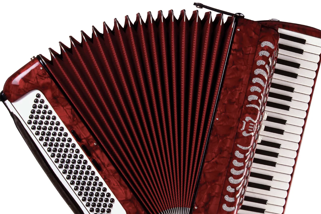
 

With a plastic spiral, we mimicked the same movement of an accordion to produce different notes. The different notes are being produced by the distance between the hand and the sensor. We have assigned a different note to each range of distances. The instrument has a switch on the circuit to turn it on or off.

Here is a video of it in action to understand better:

IMG_8161-2

Code:

Again, assembling the circuit was a challenging task, but we managed to make it work! The code is straightforward and includes an ultrasonic sensor and a switch and loop function repeatedly used. The ultrasonic sensor to measure the distance to an object then converts this distance to centimeters based on the speed of sound. Depending on these values, we determine whether to play a musical note. If the distance is outside our defined range or the force is below our certain threshold, we make sure to stop playing the note. Otherwise, if enough force is applied then the distance is matched to the value in an array of musical notes based on distance and plays it using a piezo buzzer.


int trig = 10;
int echo = 11;
long duration;
long distance;
int force;

void setup() {
  pinMode(echo, INPUT);

  pinMode(trig, OUTPUT);

  Serial.begin(9600);
}

void loop() {
  digitalWrite(trig, LOW); //triggers on/off and then reads data
  delayMicroseconds(2);
  digitalWrite(trig, HIGH);
  delayMicroseconds(10);
  digitalWrite(trig, LOW);
  duration = pulseIn(echo, HIGH);
  distance = (duration / 2) * .0344;    //344 m/s = speed of sound. We're converting into cm


  int notes[7] = {261, 294, 329, 349, 392, 440, 494}; //Putting several notes in an array
  //          mid C  D   E   F   G   A   B

  force = analogRead(A0); //defining force as FSR data


  if (distance < 0 || distance > 50 || force < 100) { //if not presed and not in front

    noTone(12); //dont play music

  }

  else if ((force > 100)) {  //if pressed

    int sound = map(distance, 0, 50, 0, 6);  //map distance to the array of notes
    tone(12, notes[sound]);  //call a certain note depending on distance

  }


}

Reflection:

In future iteration i would love to make it look more like an accordion and also sound like it more, since for now the notes don’t sound as musical as I would like. However in the end i love this simple version of it that does the job really well and looks very cute.

Final Project Draft

Currently I have figured out the connection between arduino and p5 so that based on poseNet I can move the servo as if it is following me. I have done this on the basis of getting the position of nose pose and sending it to arduino mapped to the servo range. Currently it works as intended however I think it might be a bit off when I am at extreme edges of the canvas video. I am thinking of rectifying by getting a distance variable for my next draft where i will use the distance between eyes to maybe get a more accurate angle.

I will follow a cardboard tutorial to make the CCTV:

let video;
let poseNet;
let pose;
let skeleton;
let loco= 0;

function setup() {
  createCanvas(640, 480);
  video = createCapture(VIDEO);
  video.hide();
  poseNet = ml5.poseNet(video, modelLoaded);
  poseNet.on('pose', gotPoses);
}

function gotPoses(poses) {
  //console.log(poses); 
  if (poses.length > 0) {
    pose = poses[0].pose;
    skeleton = poses[0].skeleton;
  }
}


function modelLoaded() {
  console.log('poseNet ready');
}

function draw() {
  
   if (!serialActive) {
    text("Press Space Bar to select Serial Port", 20, 30);
  } else {
    text("Connected", 20, 30);
  }
  
  image(video, 0, 0);

  if (pose) {
    
    fill(255, 0, 0);
    ellipse(pose.nose.x, pose.nose.y, 20);
   
    loco = int(pose.nose.x);
    val = int(map(loco, 0, 640, 0, 180));

    print(val)
    
  
  }
}

function keyPressed() {
  if (key == " ") {
    // important to have in order to start the serial connection!!
    setUpSerial();
  }
}

function readSerial(data) {
  ////////////////////////////////////
  //READ FROM ARDUINO HERE
  ////////////////////////////////////

  if (data != null) {
    // make sure there is actually a message
    // split the message
    let fromArduino = split(trim(data), ",");
    // if the right length, then proceed
    if (fromArduino.length == 2) {
      // only store values here
      // do everything with those values in the main draw loop
      print("nice");
      // We take the string we get from Arduino and explicitly
      // convert it to a number by using int()
      // e.g. "103" becomes 103
    
    }

    //////////////////////////////////
    //SEND TO ARDUINO HERE (handshake)
    //////////////////////////////////
    let sendToArduino = val + "\n";
    writeSerial(sendToArduino);
    
  }
}

P5 👆

#include <Servo.h>

Servo myservo;  // create servo object to control a servo


void setup() {

  Serial.begin(9600);

  myservo.attach(9);

  // start the handshake
  while (Serial.available() <= 0) {
    digitalWrite(LED_BUILTIN, HIGH); // on/blink while waiting for serial data
    Serial.println("0,0"); // send a starting message
    delay(300);            // wait 1/3 second
    digitalWrite(LED_BUILTIN, LOW);
    delay(50);
           myservo.write(90);                  // sets the servo position according to the scaled value

  }
}

void loop() {
  // wait for data from p5 before doing something
  
  while (Serial.available()) {
    Serial.println("0,0");
    digitalWrite(LED_BUILTIN, HIGH); // led on while receiving data
    int value = Serial.parseInt();
    if (Serial.read() == '\n') {
       myservo.write(value);                  // sets the servo position according to the scaled value
    }
  }
}

arduino 👆

trial video: https://youtube.com/shorts/h1etPCv24vA


Final Project – Idea Finalization

In my last post, I’ve already shared most of what my  game may be and how it’ll work. However, there have been more adjustments and decisions made and I would like to share my final project idea.

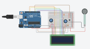
I have finalized the idea as the bubble shooter game (shown in the image above). The required functions are simple- the player should be able to choose directions and shoot bubbles. So, I would like to clarify how I will be using different components of the arduino and its sensors.

My bubble shooter game will have a gauge, that will increase as the player manages to remove certain number of lines. I plan to show this on the LCD screen.

Once this gauge is full, the player will be able to punch on the force sensor, which will work as an item that will break additional 3-5 lines of bubbles.

The player will be able to adjust the direction of bubbles being shot with the potentiometer and the shot will be made with a push button.

As of now, getting the graphics on p5js is the biggest issue and the primary goal so I’ve been focusing on it. I plan to get the graphics done and work on the different parts of the arduino, and connect them.

final project – finalized concept

concept:

Because I already made a game for my midterm project, I wanted to make my final project more of an artistic immersive experience. Specifically, I wanted to build off of the musical instrument that we made recently for one of our assignments. Instead of an instrument, however, this will be more focused on being a soundscape, with dynamic visualizations. However, instead of musical notes, I want to use sounds. The user will generate sounds based on physical input. Essentially, I want the user to be able to switch between two soundscapes – day and night – which will be based on the light of the room. And then by using force sensors and/or pressing buttons, the user will be able to generate sound.

hardware:

a light sensor, force sensor, buttons

p5.js code:

I hope to use the p5.js that produces visualizers similar to  this and this, except based on user input from the Arduino.

arduino code:

The Arduino IDE will collect the data from the sensors, i.e. how much light in the room to define the colours, and the force sensors/buttons mapping to the sound being produced.

Final Project Progress #2

Finalized concept for the project:

As I was thinking about my idea (and as Spotify Wrapped came out), I remembered last year’s Spotify’s Wrapped element where the application generated a gradient based on the top music moods. Here is an image of what I am referring to:

Therefore, I decided to stick to the colors but to change the purpose and the idea of the game. Instead of making it a game, I want my project to be a personalized experience for the user. The users will be prompted to input colors that represent different emotions to them, such as happiness, sadness, anger, etc. The input will happen with the help of 3 potentiometers, where each potentiometer will represent Red, Green and Blue. After the input is done, a personal color or a gradient will be generated, that perhaps with a click of a button can be downloaded and then sent to the user’s personal device.

Arduino Program:

Arduino setup:

  • 3 potentiometers (I saw we have bigger potentiometers in the IM Lab, perhaps I could use those)
  • buttons (for progressing through the game and the download of the result)

Arduino Program:

The Arduino program will receive the values from the potentiometers and map them to the color range from 0 to 255. It will also receive the input from the buttons and send them to P5js.

P5 Program:

P5 will be responsible for displaying the correct screens and stages of the experience (such as in the midterm project). It will also be responsible for providing real-time feedback on the color being generated by receiving the values from potentiometers and Arduino. P5 will store the input colors and use them to generate the final result.


Final Project Proposal – Twisted Twister!

Board games have always captured my interest, and for my final project, I’ve decided to reimagine the classic multiplayer game, Twister, by transforming it into an engaging solo experience. In this adapted version, I aim to introduce interactive elements, to enhance the traditional Twister setup.

Game Components:

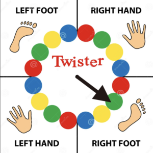
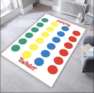
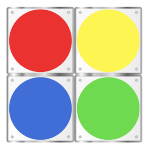
In the standard version of the game, participants spin a wheel to determine a color and a designated body part (hands or feet). Subsequently, players must position the indicated body part onto the corresponding colored circle on the Twister mat. The objective is to avoid losing balance, and if the player falls down, they lose. For the physical setup in my version, I plan to craft the Twister mat using acrylic sheets. Under each colored circle, I will integrate force sensors to detect whether a player has placed their palm or foot on the designated spot. This modification eliminates the need for multiple players while retaining the essence of the original game.

Spinning wheel


Digital Interface with p5js:

Utilizing the p5js interface, I intend to create a virtual spinner that dictates the next move for the player. p5js will not only control the wheel spinning but also manage the game score and determine win/loss conditions and the start & end of the game.

Additional Gameplay Elements:

To introduce a new challenge, I plan to incorporate ultrasonic sensors. In the classic game there is one option on the wheel that if landed on, the users have to keep their body part in the air. In this version, When the wheel lands on a specific option, players must extend their hands or feet to a particular distance, as detected by the sensors. 

Wheel Spinning Mechanism: Considering the physical nature of the game that actively uses the player’s hands, I’m exploring two potential options for spinning the wheel through p5js instead of directly clicking it on the laptop. One approach involves a switch on the Twister mat that, when pressed, triggers the p5js interface to spin the wheel. Alternatively, I’m considering a voice-activated mechanism where saying the word ‘spin’ initiates the wheel rotation.

Twister mat with acrylic sheets

Arduino Circuit: The Arduino circuit will be straightforward, connecting switches and force sensors to the Twister mat. However, I’m intrigued by the possibility of incorporating flex sensors/motors to introduce more complexity and fun to the game. These additions could potentially respond to the player’s movements, making the experience even more interactive.

Considerations:

While developing the game, I recognize the need to redefine the losing condition for a single-player setup. Unlike the traditional game where a player falls to signify defeat, I aim to explore alternative practical criteria that maintain the challenge and excitement without relying on physical falls in a solo context. By combining physical and digital elements, along with creative twists to the gameplay, I hope to transform Twister into a captivating and entertaining game experience.

Week 12: Final Project Proposal

Finalized Concept:

For my final project of the semester, I want to incorporate my love for music, inspired by an idea I had worked on before in a different class last semester. In Making Music, we had an assignment to create a drum kit out of “everyday” sounds. It was really interesting to listen to music tracks created purely out of “everyday” sounds. For my project I want to create an interactive drum kit, where the user presses on a button to choose one of the multiple themes available. Then the user can use their fingers to hit the “drum plates”, which are going to be placed on force sensors. Depending on which theme they are on, they would get different sounds from each plate.I will include one regular drum kit and multiple unusual ones. Additionally, I want to include a feature where a user can record up to 10 seconds of music as well. When the recording is complete it is attached to previous users’ recordings so that at the end of the night, I have a recording of different people playing different drum kits each using their own style. I also would like to include a feature that allows users to listen to the cumulative recording at any point. My idea is to mix everyday sounds, to sound like unusual drum kits, and allow users to improvise for a bit and mashup their improvisation later on to have a piece of music that is reflective of our different personalities. My idea is to implement it as a virtual studio, each room in the studio has a different theme and a different drum kit.

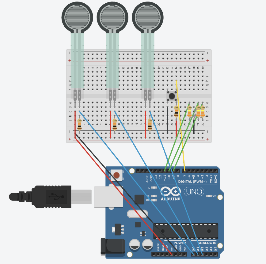
Input from Arduino: Force sensors, button

Output from Arduino: RGB LED that displays different colors depending on what theme they are on

Arduino code:

The Arduino code will read values from the sensors and send them to p5js, it will also change the color of the RGB LED by receiving a value from p5js and acting accordingly

Input from P5js: Space bar to record a short performance, if possible. Enter to return to homepage.

Output from P5js: Sounds, screen display

P5js code:

The P5js code will control the display of the themes by reading the switch values sent from the Arduino. It will also trigger sound files according to the data sent from the force sensors by the Arduino. Additionally, it would control the recording process and the playback of the recordings.

Schematic: 

Arduino schematic

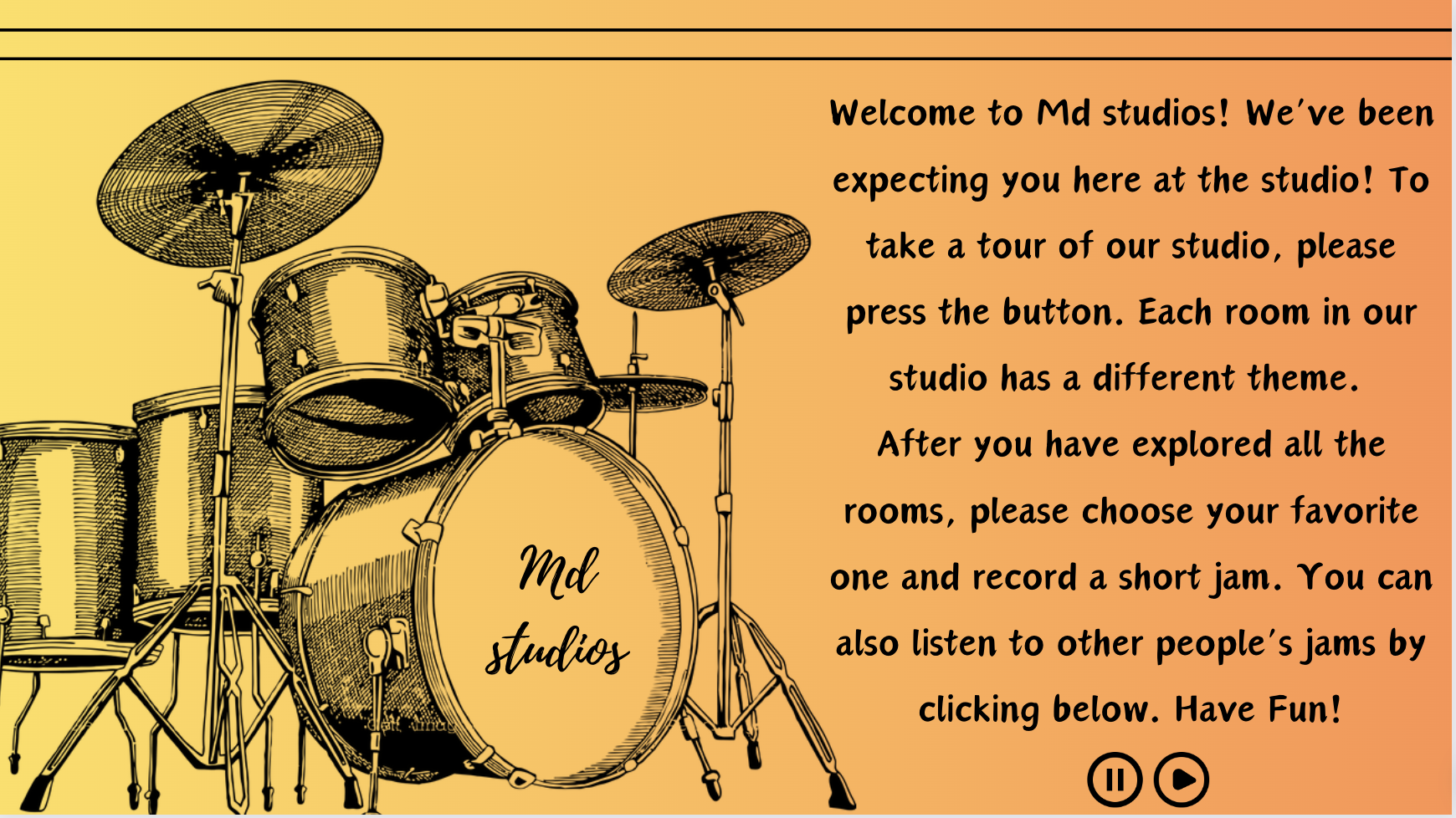
This is the initial design of my home p5js screen, but I have not designed the other themed screens yet, so I am not sure if I would stick with the same vibe for my project. I might change it if necessary when I am implementing the other screens as well:

Homepage initial design


Week 12 – Final Project Description

FINALIZED CONCEPT

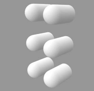
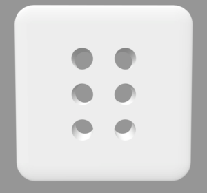
I decided to stick with the idea of creating a Braille reader. The design of the device will be close to this, but I’m thinking about adding an additional hole for the light sensor, which will detect if the finger is placed on the device.

The platform will be the size of an index finger, allowing the user to use the device in limited spaces.

The solenoids will be used to put the parts into motion and will be controlled by the Arduino program, which will control their state. As my device is designed for people with sight problems, I will use the P5 only for the audio functions, allowing a person to get familiar with the functionality of the device on their own.

I will provide the user with two modes, controlled by the switches: reading mode and alphabet mode. Moreover, there will be one additional switch allowing the user to stop the program completely. In the reading mode, the device will work according to the texts downloaded into P5, while the alphabet mode will teach a person the alphabet while providing a sound accompaniment to the program.

The P5 sketch will receive information about the state of the switches, and if the Alphabet mode is activated, it will start receiving information from the Arduino about the state of the solenoids and, according to that, sounding out the corresponding letters.

Final Project

Concept: 

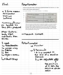
For the final project, I decided to go with the running experience. For this project, I will use a potentiometer, wires, and a band to create a circuit that will receive data from the user (motion) and translate it into a visible visual to P5js. 

I have been trying to collect data and learn more about the potentiometer and how to make the project a reality. 

Arduino Design: 

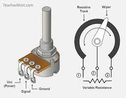
For the circuit, I will connect one end of the potentiometer to 5v, another to GND, and the third to an analog pin and a band attached to the user.

In this case, the input is the Potentiometer Data, which presents the running speed, and the output will transfer the values to the computer for further manipulation. 

I will also try to make the band and the potentiometer appealing to the user and maximize safety while using. 

P5js Design:

I have to create a start button for users to start the experience. Then, I have to constantly update the 

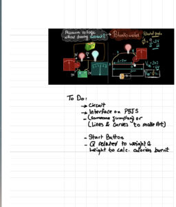
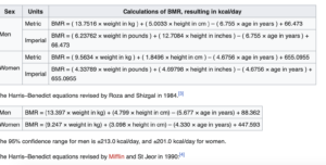
canvas with the speed obtained from Arduino. Finally, I have to use the data to estimate the calories burned probably using the Harris-Benedict equation. 

https://www.omnicalculator.com/health/bmr-harris-benedict-equation

P5 will receive data from Arduino. Then it will visually display the results in real-time. I am still not sure if I will make a character that would run at the same speed as the user, or an object, or maybe translate the data into an artwork for the user to have. 

After the person is done they will have the amount of calories burnt during the the running time. This way the project would be helpful but also fun for the user. 

Final Project Draft 1

My aim in this project was to try and make a game that allows the player to help sell pie.

Using the serial connectios the player should be able to use the potentiometer in order to get the wanted order. When one is chosen they press a button to confirm the choice.

The game goes for 2.5 minuts and the player must complete as many orders as possible.


So far I have this

P5.js sketch:

let x = 0;

let backgroundImage;
let rawImage, undercookedImage, perfectImage, overcookedImage, burntImage;

function preload() {
  // Load background image only for now
  backgroundImage = loadImage('Background.jpg');
}

function loadFoodImages() {
  // Load images after the serial connection starts
  rawImage = loadImage('raw.jpg');
  undercookedImage = loadImage('undercooked.jpg');
  perfectImage = loadImage('perfect.jpg');
  overcookedImage = loadImage('overcooked.jpg');
  burntImage = loadImage('burnt.jpg');
}

function setup() {
  createCanvas(640, 480);
  textSize(18);
}

function draw() {
  // Display background image
  image(backgroundImage, 0, 0, width, height);

  // Display image based on the value of x
  displayFoodImage();
  
  // Display serial connection status
  fill(0);
  if (!serialActive) {
    text("Press Space Bar to select Serial Port", 20, 30);
  } else {
    text("Connected", 20, 30);
  }
}

function displayFoodImage() {
  // Define the ranges for each image
  const rawRange = [0, 200];
  const undercookedRange = [201, 400];
  const perfectRange = [401, 600];
  const overcookedRange = [601, 800];
  const burntRange = [801, 1023];

  // Map x to the corresponding image based on the ranges
  let currentImage;
  if (x >= rawRange[0] && x <= rawRange[1]) {
    currentImage = rawImage;
  } else if (x >= undercookedRange[0] && x <= undercookedRange[1]) {
    currentImage = undercookedImage;
  } else if (x >= perfectRange[0] && x <= perfectRange[1]) {
    currentImage = perfectImage;
  } else if (x >= overcookedRange[0] && x <= overcookedRange[1]) {
    currentImage = overcookedImage;
  } else if (x >= burntRange[0] && x <= burntRange[1]) {
    currentImage = burntImage;
  }

  // Display the current image
  if (currentImage) {  // Check if the image is defined
    image(currentImage, width / 2 - 50, height / 2 - 50, 100, 100);
  }
}

function keyPressed() {
  if (key == " ") {
    // Important to have in order to start the serial connection!!
    setUpSerial();
  }
}

// This function will be called by the web-serial library
// with each new *line* of data. The serial library reads
// the data until the newline and then gives it to us through
// this callback function
function readSerial(data) {
  ////////////////////////////////////
  // READ FROM ARDUINO HERE
  ////////////////////////////////////
  if (data != null) {
    x = int(trim(data));
    
    // Load images only when the serial connection starts
    if (serialActive) {
      loadFoodImages();
    }
  }
}


Arduino sketch:

int sensorPin = A0;  
int sensorValue;

void setup() {
  Serial.begin(9600);
}

void loop() {
  // Read the sensor value
  sensorValue = analogRead(sensorPin);

  // Print the sensor value to the serial port
  Serial.println(sensorValue);

  delay(100);  
}


Circuit:

My potineometer works just fine. I still need to

-Display the required image according the the divided readings of the potineometer

-work on the button as a submitted answer

-figure out how to add timer and end results (maybe a leadboard)

-add sounds

-Finalize Instructions