Week 11 – Final Project Idea

Concept: A Digital Petting Zoo

For the final project, as we are required to combine both Arduino and p5js, I decided to do a digital petting zoo. I take the inspiration from an actual petting zoo, which looks like this:

Petting zoos under threat following health inquiry

In this digital petting zoo, the p5js will act like a map of the zoo and shows the information about the animals. The visitor will be able to navigate the zoo using controllers connected to Arduino. In this zoo, I plan to have three to four animals. For these animals, I plan to make physical prototypes using cardboards and other materials. These physical prototypes will be equipped with different sensors according to different animals so that the visitor can interact with them. For example, some shy animal may have a distance sensor while outgoing one might have a light sensor so that it can sense the petting of the visitor.

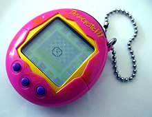
Additionally, to add some fun to the experience, there will be some tasks for the visitor to complete, such as feeding them, petting them, etc. This sort of imitates the famous old device, a Tamagotchi:

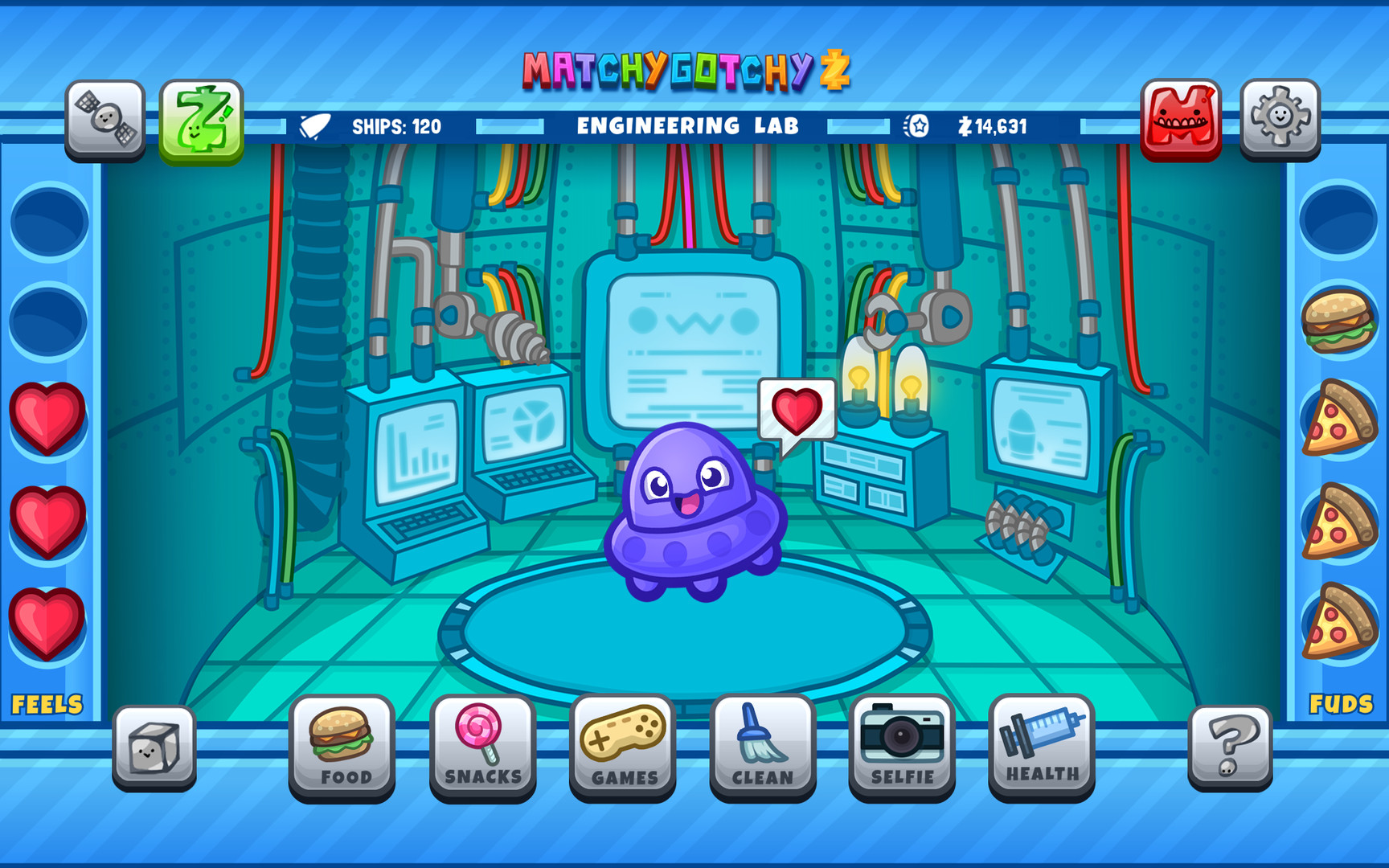
The user interface should represent something like this:

MatchyGotchy Z on Steam

Therefore, this project aims at making the visitor feel like walking around a petting zoo as well taking care of the animals there using Arduino and p5js.

Week 11 : Reflection

The writer says that in the past, people thought it was better to keep disabilities hidden when making things, and that’s not good. It doesn’t just hide a part of the person but can also make them feel like they should be embarrassed about their disability, which is a part of who they are.

They talk about things made for people with disabilities, like glasses. Glasses show how some people don’t follow the old way of thinking. There are many types and styles of glasses, so people can choose what feels comfy and looks good to them. Some people even wear glasses just because they like how they look, even if they don’t need them to see better. But when they talk about something like a fake leg for someone who lost a leg, some people might think it doesn’t look good and hide it, even if it works fine. I really think this should change. No one should feel bad about having a disability.

I think the main problem isn’t the disability itself; it’s more about the places and things around that make it hard for people with disabilities. When places don’t have things that make it easy for them, it’s tough for them to do things like everyone else. So, if we make places easy to use for everyone and remove things that make it hard, it can help people with disabilities do things more easily and feel like they’re a part of everything.

Lastly, I agree that these things should be simple. When we make things for people with disabilities, the main goal is to help them. The things should be easy for them to use without making them feel stressed.

3 Examples

Process:

For this assignment, we had to finish the three in-class examples that connect p5js and Arduino. In the beginning, I thought I understood the code and the connection but then I realized that I did not fully understand it. So I decided to review it line by line and try to understand the communication between Arduino and P5js.

Then Yupu and I decided to work together on these three examples we divided them so that he worked on the first one I worked on the second and we both worked on the third together. We helped each other debug the code and figure out how to implement it together. Honestly, this process of debugging helped me understand the communication between the two (P5js and Arduino) better.

Example 1: Circle Moving


// Week 11.2 Serial port - Light sensor, ball and light example 1 


int leftLedPin = 7;
int rightLedPin = 4;


void setup() {
 // Start serial communication so we can send data
 // over the USB connection to our p5js sketch
 Serial.begin(9600);


 // We'll use the builtin LED as a status output.
 // We can't use the serial monitor since the serial connection is
 // used to communicate to p5js and only one application on the computer
 // can use a serial port at once.
 pinMode(LED_BUILTIN, OUTPUT);


 // Outputs on these pins
 pinMode(leftLedPin, OUTPUT);
 pinMode(rightLedPin, OUTPUT);


 // Blink them so we can check the wiring
 digitalWrite(leftLedPin, HIGH);
 digitalWrite(rightLedPin, HIGH);
 delay(200);
 digitalWrite(leftLedPin, LOW);
 digitalWrite(rightLedPin, LOW);


 // start the handshake
  while (Serial.available() <= 0) {
    digitalWrite(LED_BUILTIN, HIGH);  // on/blink while waiting for serial data
      Serial.println("0,0");            // send a starting message
    delay(300);                       // wait 1/3 second
    digitalWrite(LED_BUILTIN, LOW);
    delay(50);
  }
}


void loop() {
 // wait for data from p5 before doing something
 while (Serial.available()) {
   digitalWrite(LED_BUILTIN, HIGH);  // led on while receiving data


   if (Serial.read() == '\n') {


     int sensor = analogRead(A1);  //potentiometer
     Serial.println(sensor);
   }
 }
 digitalWrite(LED_BUILTIN, LOW);
}


Example 2: LED Brightness

// Week 11.2 Example LED brightness


int leftLedPin = 6;

void setup() {
  // Start serial communication so we can send data
  // over the USB connection to our p5js sketch
  Serial.begin(9600);


  // We'll use the builtin LED as a status output.
  // We can't use the serial monitor since the serial connection is
  // used to communicate to p5js and only one application on the computer
  // can use a serial port at once.
  pinMode(LED_BUILTIN, OUTPUT);

  // Outputs on these pins
  pinMode(leftLedPin, OUTPUT);

  // start the handshake
  while (Serial.available() <= 0) {
    digitalWrite(LED_BUILTIN, HIGH);  // on/blink while waiting for serial data
    Serial.println("0,0");            // send a starting message
    delay(200);                       // wait 1/3 second
    digitalWrite(LED_BUILTIN, LOW);
    delay(200);
  }
}


void loop() {
  // wait for data from p5 before doing something
  while (Serial.available()) {
    digitalWrite(LED_BUILTIN, HIGH);  // led on while receiving data

    int brightness = Serial.parseInt();
    analogWrite(leftLedPin, brightness);
    if (Serial.read() == '\n') {
      Serial.println("0,0");
    }
  }
  digitalWrite(LED_BUILTIN, LOW);
}


Example 3:  Gravity, Ball, and LED

// week 11 example 3 sensor analg and digital light and abouncing ball 

int leftLedPin = 7;
int rightLedPin = 4;


void setup() {
 // Start serial communication so we can send data
 // over the USB connection to our p5js sketch
 Serial.begin(9600);


 // We'll use the builtin LED as a status output.
 // We can't use the serial monitor since the serial connection is
 // used to communicate to p5js and only one application on the computer
 // can use a serial port at once.
 pinMode(LED_BUILTIN, OUTPUT);


 // Outputs on these pins
 pinMode(leftLedPin, OUTPUT);
 pinMode(rightLedPin, OUTPUT);


 // Blink them so we can check the wiring
 digitalWrite(leftLedPin, HIGH);
 digitalWrite(rightLedPin, HIGH);
 delay(200);
 digitalWrite(leftLedPin, LOW);
 digitalWrite(rightLedPin, LOW);


 // start the handshake
  while (Serial.available() <= 0) {
    digitalWrite(LED_BUILTIN, HIGH);  // on/blink while waiting for serial data
    Serial.println("0,0");            // send a starting message
    delay(300);                       // wait 1/3 second
    digitalWrite(LED_BUILTIN, LOW);
    delay(50);
  }
}


void loop() {
 // wait for data from p5 before doing something
 while (Serial.available()) {
   digitalWrite(LED_BUILTIN, HIGH);  // led on while receiving data


   int LED_STATE = Serial.parseInt();
   //int right = Serial.parseInt();
   if (Serial.read() == '\n') {
     digitalWrite(rightLedPin, LED_STATE);
     int sensor2 = analogRead(A1);
     delay(5);
     Serial.print(sensor2);
     Serial.print(',');
     Serial.println('Y');
   }
 }
 digitalWrite(LED_BUILTIN, LOW);
}


Final Project Ideas

Idea 1

I would like to combine my midterm project with the final project, creating a tool that allows a person to learn to play the piano with a midi keyboard. My sketch on P5 will offer a user a variety of songs and an opportunity to add unique ones. The key that needs to be pressed will be shown on the screen, and if the right key is pressed, Sketch will show the next key.

Idea 2

During the last reading, I came up with the idea of creating a device that would allow blind and deaf, or blind people to read Braille. It would look like a small platform for a finger, which will have six points. The device will elevate the points according to the letters they represent in Braille. The user will be able to control the speed of the reading and upload their own text.

Week 11 – Series Connection

Exercise 1: make something that uses only one sensor on arduino and makes the ellipse in p5 move on the horizontal axis, in the middle of the screen, and nothing on arduino is controlled by p5

Using the ultrasound sensor, the circle moves horizontally on the canvas.

Video: exercise_1_week_11


Arduino code:

#define echoPin 2
#define trigPin 3


long duration;
int distance;


void setup() {
pinMode(trigPin, OUTPUT);
pinMode(echoPin, INPUT);
Serial.begin(9600);


}


void loop() {
digitalWrite(trigPin, HIGH);
delayMicroseconds(10);
digitalWrite(trigPin, LOW);
duration = pulseIn(echoPin, HIGH);


// Calculate distance in centimeters
distance = duration * 0.034 / 2;


Serial.println(distance); // Print distance in centimeters
delay(100); // Delay for stability
}

Exercise 2: make something that controls the LED brightness from p5. 

The LED brightness is controlled by the vertical distance of MouseY and the top of the screen. The higher the distance the brighter the LED. So, when the user drags the ellipse from the top to the bottom of the canvas, the brightness of the LED increases proportionally and vice versa.

Video: exercise_2_week_11

Arduino code:

//exercise 2, week 11, controlling the brightness of LED with p5.js
//Diana and Buka
// Output:
// - 5 - LED

const int ledPin = 5; //the LED pin is at 5

void setup() {
 // Start serial communication so we can send data
 // over the USB connection to our p5js sketch
 Serial.begin(9600);
 // use the builtin LED as a status output.
 pinMode(LED_BUILTIN, OUTPUT);
 pinMode(ledPin, OUTPUT);

 // Start the handshake
 while (Serial.available() <= 0) {
   digitalWrite(LED_BUILTIN, HIGH); // on/blink while waiting for serial data
   Serial.println("0"); // send a starting message
   delay(300); // wait 1/3 second
   digitalWrite(LED_BUILTIN, LOW);
   delay(50);
 }
}

void loop() {
 // Wait for data from p5 before doing something
 while (Serial.available()) {
   digitalWrite(LED_BUILTIN, HIGH); // LED on while receiving data
   // reading the integer value, confirming that the next character is a new line and sending confirmation 1
   int brightness = Serial.parseInt();
   if (Serial.read() == '\n') {
     delay(5);
     Serial.println("1");
   }

   // LED brightness is set accordingly
   analogWrite(ledPin, brightness);
 }
 digitalWrite(LED_BUILTIN, LOW);
}

Exercise 3: take the gravity wind example and make it so every time the ball bounces one led lights up and then turns off, and you can control the wind from one analog sensor

The LED is on when the ball is on the ground / hits the ground when bouncing. And the ball can be controlled by the potentiometer to move left and right.

Video: exercise_3_week_11.mov

Arduino code:

const int LED_PIN = 3;
const int SENSOR_PIN = A2;


void setup() {
Serial.begin(9600);
pinMode(LED_PIN, OUTPUT);


// Test the LED
digitalWrite(LED_PIN, HIGH);
delay(500);
digitalWrite(LED_PIN, LOW);
}


void loop() {
int p_value = analogRead(SENSOR_PIN); // read from the potentiometer
int move = map(p_value, 0, 1023, -1, 2); // map the value to -1, 0, and 1
Serial.println(move);


if (Serial.available() > 0) {
// read from p5.js
int touch = Serial.parseInt();
// set the LED command
if (touch == 1) {
digitalWrite(LED_PIN, HIGH);
} else {
digitalWrite(LED_PIN, LOW);
}
}
}


Week 11: Exercises

Exercise 1: make something that uses only one sensor on arduino and makes the ellipse in p5 move on the horizontal axis, in the middle of the screen, and nothing on arduino is controlled by p5

Using the ultrasound sensor, the circle moves horizontally on the canvas.

Video: exercise_1_week_11

P5.js link:


Arduino code: 

#define echoPin 2
#define trigPin 3

long duration;
int distance;

void setup() {
pinMode(trigPin, OUTPUT);
pinMode(echoPin, INPUT);
Serial.begin(9600);

}

void loop() {
digitalWrite(trigPin, HIGH);
delayMicroseconds(10);
digitalWrite(trigPin, LOW);
duration = pulseIn(echoPin, HIGH);

// Calculate distance in centimeters
distance = duration * 0.034 / 2;

Serial.println(distance); // Print distance in centimeters
delay(100); // Delay for stability
}

Exercise 2: make something that controls the LED brightness from p5. 

The LED brightness is controlled by the vertical distance of MouseY and the top of the screen. The higher the distance the brighter the LED. So, when the user drags the ellipse from the top to the bottom of the canvas, the brightness of the LED increases proportionally and vice versa.

Video: exercise_2_week_11

P5.js link: 

Arduino code:

//exercise 2, week 11, controlling the brightness of LED with p5.js
//Diana and Buka
// Output:
// - 5 - LED

const int ledPin = 5; //the LED pin is at 5

void setup() {
 // Start serial communication so we can send data
 // over the USB connection to our p5js sketch
 Serial.begin(9600);
 // use the builtin LED as a status output.
 pinMode(LED_BUILTIN, OUTPUT);
 pinMode(ledPin, OUTPUT);

 // Start the handshake
 while (Serial.available() <= 0) {
   digitalWrite(LED_BUILTIN, HIGH); // on/blink while waiting for serial data
   Serial.println("0"); // send a starting message
   delay(300); // wait 1/3 second
   digitalWrite(LED_BUILTIN, LOW);
   delay(50);
 }
}

void loop() {
 // Wait for data from p5 before doing something
 while (Serial.available()) {
   digitalWrite(LED_BUILTIN, HIGH); // LED on while receiving data
   // reading the integer value, confirming that the next character is a new line and sending confirmation 1
   int brightness = Serial.parseInt();
   if (Serial.read() == '\n') {
     delay(5);
     Serial.println("1");
   }

   // LED brightness is set accordingly
   analogWrite(ledPin, brightness);
 }
 digitalWrite(LED_BUILTIN, LOW);
}

Exercise 3: take the gravity wind example and make it so every time the ball bounces one led lights up and then turns off, and you can control the wind from one analog sensor

The LED is on when the ball is on the ground / hits the ground when bouncing. And the ball can be controlled by the potentiometer to move left and right.

Video: exercise_3_weel11.mov

P5.js link:

Arduino code: 

const int LED_PIN = 3;
const int SENSOR_PIN = A2;


void setup() {
Serial.begin(9600);
pinMode(LED_PIN, OUTPUT);


// Test the LED
digitalWrite(LED_PIN, HIGH);
delay(500);
digitalWrite(LED_PIN, LOW);
}


void loop() {
int p_value = analogRead(SENSOR_PIN); // read from the potentiometer
int move = map(p_value, 0, 1023, -1, 2); // map the value to -1, 0, and 1
Serial.println(move);


if (Serial.available() > 0) {
// read from p5.js
int touch = Serial.parseInt();
// set the LED command
if (touch == 1) {
digitalWrite(LED_PIN, HIGH);
} else {
digitalWrite(LED_PIN, LOW);
}
}
}

Week 11 – Final Project Proposal

Horse Race

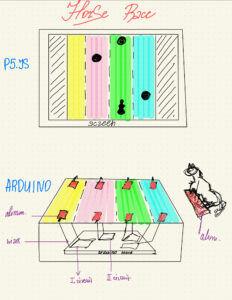
Concept: Historically, Kazakhs are nomadic people, migrating from one place to another every season of the year. Because of this, we have many national games and traditions connected with horse riding. I would like to connect my final project with one of the Kazakh national games called Båige, which means competition in horse riding. The people compete with each other in horse riding, so the winner is the person who comes first to the finish line. Throughout the game, there might be several barriers the equestrians should successfully overcome. In my game, I would like to make four lines with the appearing barriers. The user is going to be the equestrian on the horse, who should overcome the obstacles, which will speed up by the time. In addition to that, I would like to add the Kazakh national music as the background sound playing throughout the game. 

The technical implementation: On the p5.js screen, there are going to be four lines with the appearing obstacles and the image of the equestrian. In front of the user, there are going to be four squares, each representing the line of the game. I will stick the aluminum to the base of the figure of the equestrian, so that when the user taps the equestrian on the square, the aluminum connects the wires, completing the circuit. In other words, when the equestrian figure taps the first square, the first circuit is completed, indicating to the p5.js that the equestrian is on the first line. 

Week 11: In class exercises

  1. make something that uses only one sensor  on Arduino and makes the ellipse in p5 move on the horizontal axis, in the middle of the screen, and nothing on arduino is controlled by p5:

For this exercise, I kept the arduino code the same as the one in the example and I expanded on the p5js code in the example to include input from the potentiometer on the arduino. Different values of the potentiometer are mapped to the x coordinates of the ellipse. This makes it move across the horizontal axis in the middle of the screen. 

/* Week 11.2 bidi serial example
 * Originally by Aaron Sherwood
 * Modified by Mangtronix
 * Modified further by Mirette Dahab
 *
 * Add this library to Sketch files
 *  https://github.com/mangtronix/IntroductionToInteractiveMedia/blob/master/code/p5.web-serial.js files
 *
 * You must include this line in your index.html (in Sketch Files) to load the
 * web-serial library
 *
 *     <script src="p5.web-serial.js"></script>
 *
 * Arduino code:
 * https://github.com/mangtronix/IntroductionToInteractiveMedia/blob/master/code/Week11Serial.ino
 */

let Y = 0;
let X = 0;
let left = 0; // True (1) if mouse is being clicked on left side of screen
let right = 0; // True (1) if mouse is being clicked on right side of screen

function setup() {
  createCanvas(640, 480);
  textSize(18);
}

function draw() {
  // one value from Arduino controls the background's red color
  background(255);
  fill(255,0,0);
  ellipse(map(X, 0, 1023, 0, width), 220, 100);

  // the other value controls the text's transparency value
  // fill(255, 0, 255, map(alpha, 0, 1023, 0, 255));

  if (!serialActive) {
    text("Press Space Bar to select Serial Port", 20, 30);
  } 


  // click on one side of the screen, one LED will light up
  // click on the other side, the other LED will light up
  if (mouseIsPressed) {
    if (mouseX <= width / 2) {
      left = 1;
    } else {
      right = 1;
    }
  } else {
    left = right = 0;
  }
}

function keyPressed() {
  if (key == " ") {
    // important to have in order to start the serial connection!!
    setUpSerial();
  }
}

// This function will be called by the web-serial library
// with each new *line* of data. The serial library reads
// the data until the newline and then gives it to us through
// this callback function
function readSerial(data) {
  ////////////////////////////////////
  //READ FROM ARDUINO HERE
  ////////////////////////////////////

  if (data != null) {
    // make sure there is actually a message
    // split the message
    let fromArduino = split(trim(data), ",");
    // if the right length, then proceed
    if (fromArduino.length == 2) {
      // only store values here
      // do everything with those values in the main draw loop
      
      // We take the string we get from Arduino and explicitly
      // convert it to a number by using int()
      // e.g. "103" becomes 103
      Y = int(fromArduino[0]);
      X = int(fromArduino[1]);
    }

    //////////////////////////////////
    //SEND TO ARDUINO HERE (handshake)
    //////////////////////////////////
    let sendToArduino = left + "," + right + "\n";
    writeSerial(sendToArduino);
  }
}

  1. make something that controls the LED brightness from p5

for this exercise, I created a short program that allows the user to control the brightness by moving the mouse around the screen, each area in the screen has a different brightness value assigned and the value is sent to the arduino to light up the led as expected.

p5js:

let brightnessVal= 0;

function setup() {
  createCanvas(400, 400);
  background(220);
}

function draw() {//control the brightness value according to the placement of the mouse on the x axis
  if(mouseX >= 0 && mouseX <= 100){
      brightnessVal = 0;
  }else if(mouseX > 100 && mouseX <= 200){
      brightnessVal = 50;
  }else if(mouseX > 200 && mouseX <= 300){
      brightnessVal = 150;
  }else if(mouseX > 300 && mouseX <= 400){
      brightnessVal = 250;
  }
  // console.log(brightnessVal);
}

function keyPressed() {
  if (key == " ") {
    // important to have in order to start the serial connection!!
    setUpSerial();
  }
}

function readSerial(data) { //sends data to arduino
  let SentData = brightnessVal + ", \n";
  writeSerial(SentData);  
}

arduino:

const int RedledPin = 5;  // assign the pin for the LED

void setup() {
  pinMode(RedledPin, OUTPUT);
  Serial.begin(9600);// Start serial communication
}

void loop() {
  Serial.println("sensor");
  if (Serial.available() > 0) {  // Check if data is available from p5.js
    int brightnessVal = Serial.parseInt();   // Read value from p5.js
    analogWrite(RedledPin, brightnessVal);
  }
}

3.take the gravity wind example (https://editor.p5js.org/aaronsherwood/sketches/I7iQrNCul) and make it so every time the ball bounces one led lights up and then turns off, and you can control the wind from one analog sensor

For this exercise, I extended the example given by creating an OnOff variable that would store whether or not the ball is hitting the ground or not and sending it to the arduino to control the LED. I also read input from the potentiometer and stored it in the wind.x variable so that it controls the wind.


p5js:

let velocity;
let gravity;
let position;
let acceleration;
let wind;
let drag = 0.99;
let mass = 50;
let OnOff = 0;

function setup() {
  createCanvas(640, 360);
  noFill();
  position = createVector(width/2, 0);
  velocity = createVector(0,0);
  acceleration = createVector(0,0);
  gravity = createVector(0, 0.5*mass);
  wind = createVector(0,0);
}

function draw() {
  background(255);
  applyForce(wind);
  applyForce(gravity);
  velocity.add(acceleration);
  velocity.mult(drag);
  position.add(velocity);
  acceleration.mult(0);
  ellipse(position.x,position.y,mass,mass);
  if (position.y > height-mass/2) {
      velocity.y *= -0.9;  // A little dampening when hitting the bottom
      position.y = height-mass/2;
  }
  if(position.y == height-mass/2 && (velocity.y > 0.5 || velocity.y < -0.5)){ 
    OnOff = 1;
  }else{
    OnOff = 0;
  }
}

function applyForce(force){
  // Newton's 2nd law: F = M * A
  // or A = F / M
  let f = p5.Vector.div(force, mass);
  acceleration.add(f);
}

function keyPressed(){
  if (keyCode == UP_ARROW) {
    // important to have in order to start the serial connection!!
    setUpSerial();
  }
  if (key==' '){
    mass=random(15, 80);
    position.y=-mass;
    velocity.mult(0);
  }
}

function readSerial(data) {

  if (data != null) {
    wind.x = data ;
    let sentData = OnOff + "\n";
    writeSerial(sentData);
  }
}

Arduino:

int ledPin = 5; 
int Potpin = A1;

void setup() {
  // Start serial communication so we can send data
  Serial.begin(9600);
  pinMode(ledPin, OUTPUT); //set led for output
  pinMode(Potpin, INPUT);//set potentiometer for input
}

void loop() {
  int windsensor = analogRead(Potpin);//read data from the potentiometer
  int wind = map(windsensor, 0, 1023, -2, 2);
  delay(10);
  if (Serial.available() > 0) { //read data from p5js
    int Val = Serial.parseInt();
    digitalWrite(ledPin, Val);
  }
}


Week 11 : Final project

The idea is to create an interactive car simulator that combines P5 and Arduino. Users will be able to simulate driving a car on a computer screen by using physical gestures detected by Arduino sensors. I would like to incorporate features such as LEDs and a horn into the system using sensors. The system aims to provide an engaging and interactive experience, where users can control various aspects of the virtual car’s behavior through their movements. Users can control the virtual car using physical gestures detected by sensors connected to Arduino. This project emphasizes careful and timely sensing of the user’s actions, translating them into responsive and engaging interactions within the virtual car simulation. The goal is to create an immersive experience that involves a dynamic exchange between the user and the simulated car, making the interaction enjoyable and interactive.

Reading Reflection – Week #11

I was glad to read about the topic of design in the context of disability and how it has historically been approached with a focus on discretion rather than aesthetics or even functionality. I found the discussed collaboration between athlete and model Aimee Mullins and designer Alexander McQueen to be beautifully inspiring. It highlights the power of design and how it can be used to transform something that is considered a pitied disadvantage into an element of individual identity. It opens a completely new direction, one that values empowerment and personal expression rather than the wish to blend in and the strive for “normal”.

As we go deeper into this evolving conversation about design and disability, I’m left wondering about the potential effects on societal perceptions. How might a more widespread acceptance of visually expressive assistive devices lead to a more inclusive sense of beauty and ability? Can collaboration between designers and people with disabilities pave the way for a cultural shift towards celebrating uniqueness rather than conforming to preconceived norms? Storieslike the one of Aimee Mullins and Alexander McQueen invite to consider the transforming role of design not only in the lives of persons with disabilities, but also in constructing a more inclusive and welcoming society that celebrates the complexity of individual experiences.