Week 9: digital & analog input/output

Concept

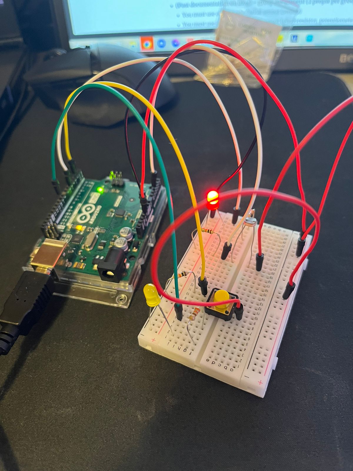
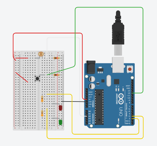
For this assignment, I decided to expand upon the concept I previously developed. In the previous assignment, I built a switch that illuminated my drawer upon opening. Given the utilization of sensors in this assignment, I contemplated enhancing the mechanism from a mechanical process to an automated one. The core idea is to enable the LED to deactivate in total darkness, and as the drawer is opened, with increasing light levels, the LED will illuminate.

Code highlight

const int LED_PIN = 9;        // the PWM pin the LED is attached to
const int LIGHT_SENSOR_PIN = A2; // the analog pin the light sensor is attached to
const int BUTTON_PIN = A3;    // the pin where the button is connected
const int EXTRA_LED_PIN = 10; // the pin for the additional LED
int brightness = 0;           // how bright the LED is
int ledState = LOW;           // initial LED state is off
int lastButtonState = LOW;    // previous button state

void setup() {
  pinMode(LED_PIN, OUTPUT);
  pinMode(EXTRA_LED_PIN, OUTPUT);
  pinMode(BUTTON_PIN, INPUT);
  Serial.begin(9600);
}

void loop() {
  int light_value = analogRead(LIGHT_SENSOR_PIN); 
  brightness = map(light_value, 0, 1023, 0, 255); 
  Serial.println(brightness);
  analogWrite(LED_PIN, brightness); // 0-255

  int buttonState = digitalRead(BUTTON_PIN);
  if (buttonState == HIGH && lastButtonState == LOW) {
    // Toggle the LED state
    ledState = (ledState == LOW) ? HIGH : LOW;

    // Update the LED state
    digitalWrite(EXTRA_LED_PIN, ledState);

    // Update the last button state
    lastButtonState = HIGH;
  } else if (buttonState == LOW) {
    lastButtonState = LOW;
  }
}

To meet the second requirement of obtaining input in a digital format, I incorporated a switch that allows the user to control the light, toggling it on or off as needed. This idea materialized during my reflections on the project when I realized one of the limitations of the initial design – it relied on the room’s illumination to function. Hence, the addition of the switch serves as an effective solution to overcome this constraint.

Reflection

Coming up with an idea for this assignment was a bit difficult but I found the process of revisiting and refining an existing idea very satisfying.

The current version kind of contradicts the intial idea but i think it still works out fine.


week9.assignment – Too Close!

Concept

When we first started working with the Arduino, I was intrigued by learning about how certain sensors work. Last year, I used an Ultrasonic Sensor for an experiment for my physics class, and once I discovered a similar but less advanced sensor in our Sparkfun kit, I was eager to understand how it functions. Additionally, since the assignment required us to use LED, I came up with an interesting idea. Similar to how a park-assist sensor works to determine the distance between the car’s bumper and a wall, I decided to use the sensor to determine how close an object is and consequently alternate the brightness of an LED based on how far away the object is. Since we hadn’t learned about the HC-SR04 distance sensor, I looked through Sparkfun’s guide, where every element of our kit was explained. There, I found a good example of how the sensor functions.

Implementation

Initially, the process seemed quite simple: connect the sensor to the breadboard, use the jumper wires to connect it to the Arduino, and use the information gathered by the sensor to manipulate an LED connected to a PWM pin, which would allow me to use analogWrite. However, as I quickly discovered, it is vital to be precise in every component of the circuit. Accidentally, I managed to overload one of the LEDs I was using, consequently burning it. I am still unsure where the issue was; however, I suspect it could’ve been the cathode of the LED which was very close to the resistor. If it had accidentally touched the starting part of the resistor, the current would jump straight into the LED before it went through the resistor and thus burnt the LED. Nevertheless, apart from this minor issue, everything else worked well and after tinkering around with the code, I was able to produce exactly what I had envisioned. One of the two LEDs was multipurpose. It can be turned on using the button (digital switch) and controlled in a digital fashion. Additionally, that same LED circuit is also connected to a different pin, which allows it to turn on once the distance sensor value exceeds a certain threshold. One other issue I encountered was with converting the data from the analog sensor into understandable units. The example provided by Sparkfun used inches as their units; however, I decided to use a ruler and experiment with the math to adjust the sensor to be accurate using centimeters. Two videos of the working project and the code are below:

Distance Detector Video

Digital Switch

const int ECHO_PIN = 12;       //input, collects data from waves
const int TRIG_PIN = 11;       //output, sends out the waves

const int RED_LED = 8;         // red to light up when objects close
const int YELLOW_LED = 6;      // yellow to fade if object getting further

float distance = 0;            // variable to store distance

void setup() {
  Serial.begin (9600);         // set up a serial connection with the computer

  pinMode(ECHO_PIN, INPUT);    // echo pin measure the duration of pulses coming back from the distance sensor
  pinMode(TRIG_PIN, OUTPUT);   // trigger pin output pulses of electricity

  //set LED pins to output
  pinMode(RED_LED, OUTPUT);
  pinMode(YELLOW_LED, OUTPUT);
  pinMode(PUSH_BUTTON, INPUT_PULLUP);
}

void loop() {
  distance = getDistance();   //variable to store distance measured by the sensor in cm

  Serial.print(distance);     //print the distance that was measured
  Serial.println(" cm");      //print units after the distance

// if conditional to control LED's depending on distance.
  if (5 <= distance && distance <= 30) {
    int brightness = map(distance, 5, 30, 255, 0);
    analogWrite(YELLOW_LED, brightness);
    digitalWrite(RED_LED, LOW);
    Serial.println(brightness);
  } else if (distance < 5) {
    digitalWrite(RED_LED, HIGH);
  } else {
    analogWrite(YELLOW_LED, 0);
    digitalWrite(RED_LED, LOW);
  }
}

float getDistance() {
  float echoTime;                   //variable to store the time it takes for a ping to bounce off an object
  float calculatedDistance;         //variable to store the distance calculated from the echo time

  //send out an ultrasonic pulse that's 10ms long
  digitalWrite(TRIG_PIN, HIGH);
  delayMicroseconds(10);
  digitalWrite(TRIG_PIN, LOW);

  echoTime = pulseIn(ECHO_PIN, HIGH);      //pulsein command to see how long it takes for pulse to bounce back to sensor

  calculatedDistance = echoTime / 55.2;    //calculate  distance of object that reflected the pulse in cm

  return calculatedDistance;               //send back calculated distance 
}
Reflection

Overall, I found this experience to be extremely useful and crucial in understanding how to find information about new sensors and objects I could use for future projects, as well as understanding how to structure the code for the collection of sensor data. I also found it extremely helpful to print out the values of the sensor to help me adjust the math calculations, which is common practice I used in P5JS to determine if everything was working well, and it translates well into the physical computing environment.

Week 9: Reading Response

From these articles by Tom Igoe, it’s clear that physical computing offers immense creativity and excitement. The examples shared in the first article, “Physical Computing’s Greatest Hits (and misses,” introduced various creative possibilities that sensors and technologies offer in creating interactive projects. It was fascinating to see how simple touch, thermal, light, and sound sensors could be integrated into creative projects that evoke emotional responses in users. The concept of the “remote hugs” project was particularly intriguing. Although Igoe explained that the user didn’t quite feel hugged, this project succeeded in radiating positivity and satisfaction, aiming to engage users on an emotional level. I particularly appreciate the idea he raised that not everything has to be entirely original, but it can be improved upon and reimagined, which is inspiring. Therefore, I am more encouraged to explore projects that can bring positivity and emotion to users in innovative ways, even if they build on existing concepts.

The second article, “Making Interactive Art: Set the Stage, Then Shut Up and Listen,” explains interactive art’s interactivity and how it should be approached. In interactive art, the core message is to create a meaningful dialogue between the artist and the user. Allowing the user to explore and interpret the artwork without explicit guidance can lead to more satisfying experiences. I think this element of surprise and discovery is crucial in interactive art, enhancing user satisfaction. I also realized that open-ended interactive pieces are particularly suited to this approach, as users can uncover the artist’s intentions by exploring various features or come up with their interpretations. Also, one thing about interactive art is that the user feels engaged in creating something by interacting with the work, which makes the project much more fun and meaningful to the user. The article also touches upon user experience design (that we have learned from previous readings by Norman), such as providing interactivity hints. It is valuable advice as it ensures that users intuitively understand how to interact with the artwork.

Week 9: Cookie Jar

Concept:

For this week, our task was to get information from at least one analog sensor and at least one digital sensor (switch), and use this information to control at least two LEDs, one in a digital fashion and the other in an analog fashion, in some creative way.
My project is called “The Cookie Jar”, and it’s inspired by my love for chocolate chip cookies.

After recklessly spending my savings on this bucket of cookies, I decided to base my project on it. The idea was to turn a light on every time I opened the lid of this cookie bucket. To do this, I had to code the photoresistor in a way that it could take the difference between the light outside and the light inside. However, the problem relied on the fact that turning on the LED also generated light by itself, so I had to adapt the constraints of it in a way that would work properly. Also, I added a switch to turn on and off manually the other light inside, just in case someone wants to sneak a cookie in the middle of the night.

Breadboard and connections: 

Demonstration:


Code: 

void setup() {
  // put your setup code here, to run once:
  Serial.begin(9600);
  pinMode(5,OUTPUT);
  pinMode(9,OUTPUT);
  pinMode(2,INPUT);
  pinMode(A2,INPUT);
}

bool lightsOn = false;
void loop() {
  // put your main code here, to run repeatedly:
  int sensorValue = analogRead(A2);
  int switchValue = digitalRead(2);
  
  if(switchValue == 1){
    lightsOn = !lightsOn;
    delay(500);
  }
  digitalWrite(9,lightsOn);
// The brightness is the difference between inside and outside, but reversed (more light if the difference is low)
  int brightness = 255-(620-sensorValue);
  if(brightness<0){
    brightness = 0;
  }
  if(brightness>255){
    brightness = 255;
  }
  analogWrite(5,brightness);
  Serial.println(sensorValue);
  
}

Challenges:

The biggest challenge I faced was the shape and the fact that I had to connect the arduino UNO inside with the lid closed. I fixed this problem by reluctantly making a hole in my cookie bucket. I opened it just enough so it could fit the USB connector, which allowed me to insert the circuit inside even with the lid closed.


Reflections – Week 9

Making Interactive Art: Set the Stage, Then Shut Up and Listen

This piece highlights the difference in making interactive art and making art. While artists (and viewers alike) generally believe that a work of art is an expression or a statement – interactive art is much different in several aspects. The artist’s role isn’t to make a statement but rather start a conversation. The viewer will then interact with this and have an experience that ideally will communicate what you want it to.

Here Tom Igoe gives practical advice as to how to make interactive art – that ultimately boils down to setting the stage, shutting up and listening to the audience. At the start of the course, this idea would have seemed foreign to me, but through both the readings and personal experiences I have come to realize what Tom intends to say here. Additionally, I love the example of the director Tom uses here, and his overall writing style!

Lastly, I believe interactive art – as the way Tom puts it – in a way serves to liberate the artist. It suggests that as an artist, one doesn’t have to bear the entire burden of meaning or impact. Instead, by creating a framework for interaction and then stepping back, an artist can allow the artwork to breathe, grow, and morph through each interaction. At the same time, it also poses a challenge: can an artist resist the urge to dictate, to instead become a facilitator of experience?

Physical Computing’s Greatest Hits (and misses)

Here Tom Igoe provides us with several examples of the kinds of physical computing works that show up frequently. Of these, I would like to reflect on 3 ideas in particular:

I particularly liked the idea of a “meditation helper”. Beyond directly building something to help with meditation. What really interests me is the concept of reading a person’s heart rate, breathing rate, etc. These factors are easily accessible these days, and it will be very interesting to build technology infused clothing that is practical and useful.

The Scooby Doo painting art type seems overdone but something about it still remains intensely creepy. I would love to incorporate something of that manner in a project I do going forwards.

Lastly, floor pads are also exciting. I am curious as to if we can somehow engineer them in a way that lets us walk in place (like a treadmill and have that actually simulate a walk for a character in real-time etc. Moreover, there’s a lot more that can be done with such pads if we keep adding layers of complexity!

Week 9 – Pedestrian Problems

Concept

For this week’s assignment, I decided to show the common problem of pedestrians when crossing the road. My idea was to create a pedestrian crossing light, which would show the common problem of having “infinite” red light and only limited actual crossing green light. I believe this is a common problem in any country and anyone can relate to the idea of this project.

Video: Pedestrian Traffic Light

Diagram, Code, Highlights, and Challenges of the Project

To make this project, I decided to break it into three steps.

Firstly, I made a switch as a push button, which will turn on the green LED. For this, I built a circuit for the switch button, which I learned from the class material. I am proud of this step, as I could apply the previous knowledge (building the circuit of the light sensor) and understand how to do the same with the switch button. I used a 10K Ω resistor, a green push button (to indicate the same color as the LED color), a green wire that connects to pin 12, a red wire that connects to 5V, and a black wire for the GND connection. One challenge I faced was forgetting that the current could not jump from one place on the breadboard to another, so I added another red wire to finish the connection.

Moreover, I made a simple circuit for the green and red light, using green and red LEDs, 2 330Ω resistors, and yellow wires connected to pins 2 and 3. I didn’t have to use an additional black wire, as I intentionally had all of my components connected in a way that uses only 1 black wire connected to GND.

As I completed building this, I wrote a simple program that will turn on the green LED, and turn off the red LED, when the green button is pushed. Moreover, I made a code for the green LED blinking. For this part of the project, I used a digital sensor and controlled it in a digital fashion.

Lastly, I decided to add an analog sensor – a light sensor – which will control the brightness of the red LED. I had no problem building this part of the circuit, however, I had to decide whether I wanted to completely turn off the red LED or control the red LED in a fashion that is independent of the digital switch. If I decided to turn off the LED using a light sensor, I would need to think about 4 different options of its connection to the switch button: switch on & sensor value >400, switch on & sensor value <400, switch off & sensor value >400, switch off & sensor value <400. I decided that independent control of the light sensor would reflect my concept better. Therefore, I made a red LED to always have a dimmed brightness, and when the light sensor is covered the LED will become brighter.

Here, is the code for my program:

// assigning variables to the pins
// push button has a connection to pin 12
// green LED has a connection to pin 2
// red LED has a connection to pin 3

int pushButton = 12;
int greenLED = 2;
int redLED = 3;

// the setup routine
void setup() {
  // initialize serial communication at 9600 bits per second:
  Serial.begin(9600);
  // make the pushbutton's pin an input
  pinMode(pushButton, INPUT);
  // make green LED and red LED pins as output
  pinMode(greenLED, OUTPUT);
  pinMode(redLED, OUTPUT);
}

// the loop routine runs over and over again forever:
void loop() {

  // read the input pin of the push button:
  int buttonState = digitalRead(pushButton);
  // print out the state of the button:
  Serial.println(buttonState);
  delay(1);  // delay in between reads for stability

  // if statement for controlling the red and green LEDs through the push button (digital switch)
  // if button is pushed
  // turn off the red LED and blink the green LED with a delay in between the blinks

  if (buttonState == HIGH) {

    digitalWrite(redLED, LOW);

    digitalWrite(greenLED, HIGH);
    delay(1000);
    digitalWrite(greenLED, LOW);
    delay(1000);

    // if button is not pushed
    // green LED is always off
    // red LED is always on
    // and the red LED is controlled by the light sensor values a.k.a. the brightness
    // if the sensor value is less than or equals to 400, the brightness of the red LED is at maximum
    // if the sensor value is more than 400, the brightness of the red LED is alway dimmed at brighness of 10

  } else {
    //if the green button is not pushed,
    // the green LED is not turning on
    digitalWrite(greenLED, LOW);

    // initializing variable called sensorValue which reads the values from A2 analog pin
    int sensorValue = analogRead(A2);

    if (sensorValue <= 400) {
      analogWrite(redLED, 255);
    } else {
      analogWrite(redLED, 10);
    }
  }
}

Future Work and Reflection

Overall, I believe that I achieved all of my goals for this project. I was able to practice the knowledge I gained during class work and apply it in a new context. I am proud of the work I have done. Although I faced several challenges, which I described above, I was able to resolve them easily. For the next work, I am planning to keep up with my method of breaking the big project into smaller parts and achieving the same good results.


Week 9 Sensors – Christmas Tree

Concept:

For this assignment, we had to get information from an analog and a digital sensor and control 2 LEDs, one with the analog and one with the digital. Since it is almost Christmas season, I wanted to create a Christmas tree lit by a light sensor and a switch separately. I really like this time of the year because it is special in my hometown. It is all about family and friends gatherings, rainy days, meaningful conversations with delicious food, and an end-of-year celebration.

Highlight:

Reviewing the lecture notes and my notes was key in constructing this assignment. I started by drawing the tree, coloring it, and marking where I wanted the LEDs to go. I had to glue things in place because the paper was not strong enough to handle all the LEDs and wires.

I was a little scared of assembling the circuit in the wrong way and creating a shot, but it worked out well. However, I had to figure out how to deal with many things to make this project work. For instance,  I  had to figure out how to make the LED anode longer. To fix this problem, I  decided to use wires and attach them to the anode and the board instead of attaching the LEDs directly to the board. It was frustrating to attach the wires to the LEDs especially to keep them in place. To distinguish between the positive and negative anodes of the LED I used foil for one and copper tape for the other. Doing so made it less confusing to attach them to the board. I had some doubts about whether the circuit was correct or not so I re-assembled them multiple times to make sure I made it correctly. Attaching the switch and the light sensor was easier. Even though I made two codes one for the switch and the other for the light sensors, on the board they both share the same GND and the 5V.

The code is like to what we did in class. I tried to figure out how to add all Pins in one line of code but I could not figure out how,

Light Sensor:

// the setup routine runs once when you press reset:
void setup() {
  // initialize serial communication at 9600 bits per second:
  Serial.begin(9600);
  pinMode(13, OUTPUT);
  pinMode(11, OUTPUT);
  pinMode(9, OUTPUT);
  pinMode(7, OUTPUT);
  pinMode(5, OUTPUT);
  pinMode(3, OUTPUT);
  pinMode(2, OUTPUT);
}

// the loop routine runs over and over again forever:
void loop() {
  // read the input on analog pin 0:
  int sensorValue = analogRead(A4);
  if (sensorValue > 255) {
    digitalWrite(13, LOW);
    digitalWrite(11, LOW);
    digitalWrite(9, LOW);
    digitalWrite(7, LOW);
    digitalWrite(5, LOW);
    digitalWrite(3, LOW);
    digitalWrite(2, LOW);
    delay(1000);  // turn the LED off by making the voltage LOW
  }
  // wait for 30 milliseconds to see the dimming effect
  else {
    digitalWrite(13, HIGH);
    digitalWrite(11, HIGH);
    digitalWrite(9, HIGH);
    digitalWrite(7, HIGH);
    digitalWrite(5, HIGH);
    digitalWrite(3, HIGH);
    digitalWrite(2, HIGH);
  }
}

Switch :

// digital pin 2 has a pushbutton attached to it. Give it a name:
int pushButton = A2;

// the setup routine runs once when you press reset:
void setup() {
  // initialize serial communication at 9600 bits per second:
  Serial.begin(9600);
  // make the pushbutton's pin an input:
  pinMode(pushButton, INPUT);
  pinMode(13, OUTPUT);
  pinMode(11, OUTPUT);
  pinMode(9, OUTPUT);
  pinMode(7, OUTPUT);
  pinMode(5, OUTPUT);
  pinMode(3, OUTPUT);
  pinMode(2, OUTPUT);
}

// the loop routine runs over and over again forever:
void loop() {
  // read the input pin:
  int buttonState = digitalRead(pushButton);
  // print out the state of the button:
 if (buttonState==1) {
  digitalWrite(13, HIGH);
    digitalWrite(11, HIGH);
    digitalWrite(9, HIGH);
    digitalWrite(7, HIGH);
    digitalWrite(5, HIGH);
    digitalWrite(3, HIGH);
    digitalWrite(2, HIGH);
  
    // turn the LED off by making the voltage LOW
  }
  // wait for 30 milliseconds to see the dimming effect
  else {
      digitalWrite(13, LOW);
    digitalWrite(11, LOW);
    digitalWrite(9, LOW);
    digitalWrite(7, LOW);
    digitalWrite(5, LOW);
    digitalWrite(3, LOW);
    digitalWrite(2, LOW);
    
    
  }
}


Reflection and future improvements:

Trusting the process was a huge reason why this project worked. It is not complicated, but it needs a lot of focus. In the future, I want to make it more presentable and neater. I want to also find a way where both the sensors work together in the same code.

Merry Christmas!

Week 9 – Light Chameleon

Concept

For this assignment, I imagined to simulate a kind of animals using just LEDs. It took me some time to decide on which animal to imitate because the information communicated by LEDs can be very limited. Then, suddenly an idea came to my mind: a chameleon that is sensitive to light! To do this, I used a light sensor and a RGB LED as the analog input and output. The RGB LED will change color as the sensor detects different amount of light, just like chameleon changing color with its environment. Besides this, I used a button and a normal LED as the digital input and out. This simulates the situation where the chameleon is found out by its predator and got eaten. So, if the button is pressed, the red normal LED will be on and the RGB LED will become white, regardless of the light sensor.

(Due to the quality of the video, the color change might not be so obvious in the video. But it works really well in reality.)


IMG_0922

Highlight of the code

The code is relatively easy. It essentially uses map() to take different ranges of RBG values and pass them to the RGB LED respectively.

#define RED_PIN 3
#define GREEN_PIN 5
#define BLUE_PIN 6
#define LED_PIN 12

void setup() {
  Serial.begin(9600);
  pinMode(RED_PIN, OUTPUT);
  pinMode(GREEN_PIN, OUTPUT);
  pinMode(BLUE_PIN, OUTPUT);
  pinMode(A0, INPUT);  //light sensor input
  pinMode(2, INPUT);   //button input
  pinMode(LED_PIN, OUTPUT);
}
int value = 0;
int buttonState = 0;
int lastButtonState = 0;
int LEDState = LOW;
void loop() {
  value = analogRead(A0);
  lastButtonState = buttonState;
  buttonState = digitalRead(2);

  // the LED is on when button is pressed, and off when button is pressed again
  if (lastButtonState == 1 && buttonState == 0) {
    LEDState = !LEDState;

    digitalWrite(LED_PIN, LEDState);
  }


  if (LEDState == HIGH) { // if the red LED is on, RGB LED is always white
    setColor(255, 255, 255);
  } else { // make the range of R, G, B different from each other
    int R = map(value, 100, 1000, 0, 255);
    int G = map(value, 100, 1000, 255, 0);
    int B = map(value, 0, 1000, 0, 100);

    setColor(R, G, B);

    Serial.println(R); // for debug
  }
}

void setColor(int R, int G, int B) {
  analogWrite(RED_PIN, R);
  analogWrite(GREEN_PIN, G);
  analogWrite(BLUE_PIN, B);

Reflection and Improvement

I think the challenge of this assignment for me is to convey meaningful messages through LEDs and their own inputs, which are relatively limited. However, the use of RGB LED gives me more flexibility and makes the project a little more interesting. If I were to improve it, I would make an actual chameleon using some materials like cardboards. This might make the concept of the assignment more visually concrete.

The Nightlight and the Alarm

Approach and Concept:

It took me a long time to come up with the idea for this project given the requirements it had. But at the end of our previous lecture, I realized I could make a night-light+morning alarm system.

For my analog input I use the light sensor we employed in class. In the morning, this turns on the buzzer (digital output 1) and the red LED light( digital output 2). While it’s night (low light) the blue LED (analog output) blinks in a slow and satisfying manner. A button (digital input switch) can be used to turn the whole system off or on at any given time.

I believe this whole system, if refined further a bit has actual practical utility, and I’m really happy I could make something like this on my own!

Highlights:

I would like to highlight both the coding and the hardware work for this project:

Coding: The system uses a state management system. When I tried to use code from the examples we used in the lecture. This became complicated because doing things like making the analog output led blink slowly couldn’t be done through for loops – or the delay would mess up with the state switching mechanism. To navigate through this, I had to remove the for loops and instead work directly with the loop function. Similarly, I faced this issue again with the buzzer where the delay’s blocking nature was causing some problems – leading me to use the external ezBuzzer library. Beyond this, joining together so many components itself was a fun challenge!

void loop() {
  buzzer.loop();
  // read the state of the pushbutton value:
  buttonState = digitalRead(buttonPin);
  int analogValue = analogRead(A0);
  // check if the pushbutton is pressed. If it is, the buttonState is HIGH:
  if (buttonState == HIGH && led_state==0) {
    while(buttonState==HIGH)
    {
      buttonState = digitalRead(buttonPin);
    // turn LED on:
      led_state=1;
    }
  }
  else if(buttonState == HIGH && led_state==1)
  {
    while(buttonState ==HIGH)
    {
      buttonState = digitalRead(buttonPin);
      led_state=0;
    }
  }
  Serial.println(led_state);
  digitalWrite(ledPin,led_state && led_stateD);
  if(led_state==0 || led_stateD==0)
  {
    if (buzzer.getState() != BUZZER_IDLE) {
      buzzer.stop() ; // stop
    }
  }
  else 
  { if (buzzer.getState() == BUZZER_IDLE) {
      int length = sizeof(noteDurations) / sizeof(int);
      buzzer.playMelody(melody, noteDurations, length); // playing
    }
  }
  if (analogValue < 300) {

    led_stateD=0;
    led_stateA=1;
  }
  else {
    led_stateD=1;
    led_stateA=0;
  }
  if(led_state==1 && led_stateA){
  // fade in from min to max in increments of 5 points:
  if(millis()%10==0) {
    // sets the value (range from 0 to 255):
    fadeValue+=increment;
    analogWrite(ledPinAnalog, fadeValue);
    if (fadeValue==255 || fadeValue==0)
      increment*=-1;
  }}
  if(led_state==0 ||led_stateA==0)
    analogWrite(ledPinAnalog, 0);

}


Hardware: The connections itself were simple enough in themselves – since I had knowledge of what we had done in class to borrow from. However, given the many elements the board itself got messy – making navigation a hassle.

Reflections and Future Work:

There are several improvements I would like to make on this work. On the technical implementation aspect, I can possible manage the wires I use much better than I have done here. And on the coding aspect, the code can definitely be made more streamlined and easier to read.

In terms of future work, I would like to add more lights to the nightlight aspect, and make the blinking pattern more complex to have a more soothing experience. Similarly, the buzzer noise and the morning alarms can also be improved aesthetically. In terms of functionality, it would be nice to have another button than can function as a snooze button.


Week 9 | Analog + Digital input & output: “Mario’s Magic Light-Up Mushroom” Assignment

Mario’s Magic Light-Up Mushroom:

The inspiration for my project struck me when I found myself without my Nintendo Switch, unable to play one of my all-time favorite games since childhood, ‘Mario Party.’ This game is filled with quirky and fun elements like the lucky block and the magical mushroom, both of which can greatly influence your journey in the game.

So, I decided to base my project on the game. It’s not only a personal passion but also a nostalgic trip down memory lane. I believe it’s a creative concept that encapsulates the magic of ‘Mario Party,’ and I had the input of my friends to help shape the idea.


IMG_5210_DEMOSTRATION VIDEO

Structure

The structure of my project revolves around the use of buttons and sensors from the SparkFun kit, which I gained an understanding of during one of our classes.

The materials I used are a printed out image of the iconic mushroom and lucky block from the game. These images were carefully mounted on cardboard for durability, and I affixed them with tape on the to ensure they could withstand the project.

The red is controlled by the sensor, The yellow is controlled by the button

The code provided in class examples played a crucial role in helping me bring this assignment to life. It served as a valuable starting point and a foundation for what I aimed to achieve. With the help of this code, I’m confident that the project will capture the fun and nostalgia of ‘Mario Party’ while showcasing my newfound skills in working with hardware and sensors.

Reflection

I must admit that the journey of building the Arduino circuit and working with the breadboard was a bit challenging, but it was also immensely rewarding. I spent a considerable amount of time understanding the components, making connections, and ensuring everything functioned as intended. While it tested my patience at times, it also provided me with invaluable insights into electronics and hardware, which I know will be useful in the future.