Feeling Snackish

This week’s assignment drew inspiration from a familiar scenario: those late-night kitchen escapades for sneaky snacks. At home, the kitchen lights, being downlighters, don’t just instantly switch on. Instead, there’s a gradual shift when we turn the knob. This unique characteristic prompted me to recreate this experience in my circuit. The analog representation was brought to life through the potentiometer, mirroring the gradual adjustment of the kitchen lights, while the digital side found expression in the toggle switch.

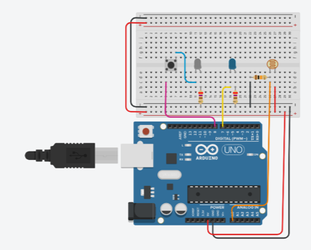
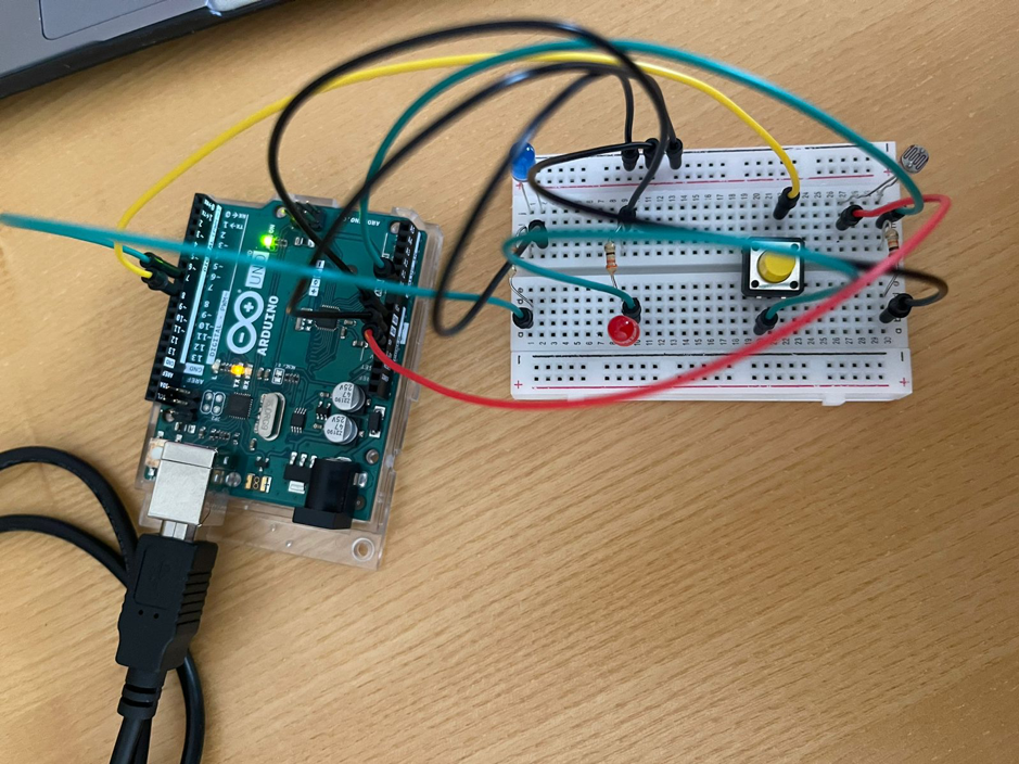
To bring my circuit to life, I gathered a few key components: a potentiometer, a toggle switch, jumper cables, two 10k ohm resistors, one 330-ohm resistor, and two LEDs. The interplay of these elements resulted in the creation of a circuit, visually captured in the image below.

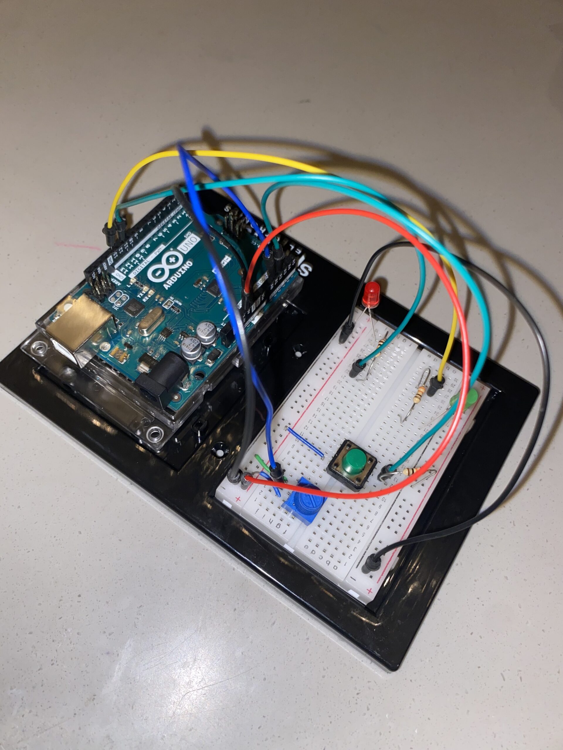
In the process of setting up the circuit, I encountered challenges associated with ensuring the correct placement of components, whether they operated in the digital or analog realm. Despite these hurdles, I noticed a significant improvement in my ability to assemble the circuit compared to my initial attempts. This project underscored the importance of understanding the specific pins corresponding to digital and analog features on the Arduino Uno board. Aligning the code with the appropriate pin modes became crucial for a seamless execution.

Here’s a snippet of the code that brought my project to life:

void loop() {
  int sensorValue= analogRead(A1);
  int buttonState = digitalRead(A2);
  Serial.println(sensorValue);


 analogWrite(led, sensorValue/4);

 delay(30);

 if (buttonState == LOW) {

digitalWrite(13, LOW);

} else {

digitalWrite(13, HIGH);

}
}

Below is the video representation of my assignment.

IMG_4150

Reflecting on the project, I recognize its conceptual completeness, yet I aspire to enhance its creative aspect. While the current iteration captures the assignment’s essence, I envision experimenting with diverse LED blinking patterns, moving beyond the conventional blink. Additionally, exploring the possibility of using the potentiometer to control multiple LEDs could add a layer of complexity and creativity to the project, elevating it beyond its current simplicity.

Luminar: Arduino-LDR LED System

Concept
In the realm of electronics, my pursuit led me to create an LDR-controlled LED system using Arduino. The concept is rooted in a personal connection—recalling my younger self’s dependence on a night light for a good night’s sleep. This assignment aims to offer a modern solution by integrating an LDR-controlled LED system, bridging the gap between past comforts and present technology.

Required Hardware
• Arduino UNO
• Light sensor
• LED’s
• Resistor (330 ohms)
• Jumper wires
• Breadboard
• USB cable
• Computer with Arduino IDE installed

Light Sensor  

Circuit Diagram
The circuit diagram was created using Tinker CAD and includes the Light sensor, LED’s, resistor, Arduino UNO, and breadboard.

Setting Up the Components

The first step was assembling the components. The LDR was connected to the analog pin A0 on the Arduino, and a resistor was added to create a voltage divider for accurate readings. One LED was directly connected to pin 7, while the second LED was attached to pin 8 through a push button.

Coding the Logic

The Arduino code was crafted to read the analog value from the LDR and determine whether the ambient light was above or below a predefined threshold. If the light level fell below the threshold, both LEDs would illuminate, creating an aesthetically pleasing effect.

int ldrPin = A0;
int led1 = 7;
int led2 = 8;  // New LED pin
int threshold = 70;

void setup()
{
  Serial.begin(9600);
  pinMode(led1, OUTPUT);
  pinMode(led2, OUTPUT);  // Set the new LED pin as OUTPUT
}

void loop()
{
  int data = analogRead(ldrPin);
  Serial.println("");
  Serial.print("Light Sensor ");
  Serial.print("Value = ");
  Serial.print(data);

  if (data <= threshold)
  {
    digitalWrite(led1, HIGH);
    digitalWrite(led2, HIGH);  // Turn on the second LED
  }
  else
  {
    digitalWrite(led1, LOW);
    digitalWrite(led2, LOW);  // Turn off the second LED
  }
}

Hardware Implementation

Video Illustration

https://youtu.be/EFwwim9_fBc

Working Explanation and Conclusion:

Experimenting using electronics enables the combination of technology and creativity. With this assignment, I investigated the dynamic control of two LEDs using an Arduino, an LDR, and a button. This is an example of the limitless possibilities that exist when imagination and technology are combined, whether it is used as an instructional tool or as a decorative lighting solution. Also, it can be used as a dark sensor if anyone want to sleep in a very light like small bulb.

Week 9 – Reading Response(s)

Making Interactive Art: Set the Stage, Then Shut Up and Listen

In this class, it’s easy to present our artworks as static pieces with instructions for the participants and a statement of how we want them to interpret it. The author of this piece, however, believes that this defeats the purpose of interactive art. He wants interactive artists to think of their artwork as a performance rather than a painting; you don’t go about narrating the plot to the audience in a performance – you let the audience perceive the performance through their own senses and interpretation. In the same way, we shouldn’t present our interactive artworks on a canvas with instructions and interpretations – we give them the basic context so they know what they’re getting into, and then we let them explore for themselves. We have to trust our audience to discover their interpretation through a ‘conversation’ with our artwork with merely a suggestion of what their course of action should be – unaided by our own directives – because only in this way can we offer an authentic emotional experience to our audience.


Physical Computing’s Biggest Hits (and misses)

This one was just a list of some of the most common project themes in interactive artwork projects. It’s funny because a lot of us will be revisiting these themes many times ourselves for our own artworks, but I don’t think there’s something deeply wrong with that. I think finding our own twist on things that have widely been done before is still our own thing. After all, it is easy to feel like everything worth doing has already been done. Not that that’s true, but I think we may just come closer to originality by stumbling upon an idea no one’s heard of before while first doing stuff that has been done, countless times over.

Week 9: Digital and Analog

Concept 

I tried to create an interactive traffic signal by integrating a push button and a potentiometer connected to two LEDs. Upon pressing the digital input push button, the red light illuminates, while the potentiometer, serving as the analog input, enables control over the brightness of the yellow light. This dual-input system represents a significant challenge, as initially, I could only manage them separately. 

Reflection: 

Coding proved to be an inspiring task, particularly in merging both analog and digital components seamlessly. Despite the initial difficulty, this project served as a valuable learning experience, providing insights into the intricacies of combining different inputs and coding for a cohesive interactive system. As I look ahead, the incorporation of the third color, red, looms as the next exciting phase, promising further growth and mastery of interactive design.

Materials used: 

  1. Arduino board 
  2. Potentiometer 
  3. 2 LEDs (red and yellow)
  4. Resistors 
  5. Tactile push-button switch
  6. Breadboard 
  7.  jumper wires

Video Links

Week 9: Reading Response

“Physical Computing’s Greatest Hits and Misses”

In this article, the author talks about things that often show up in projects using physical computing. They say we should see these things as a kind of creative playground, not as limits. It’s like having a favorite game on the playground – it’s familiar, but the real fun starts when you add your special twist. The article mentions the Mattel/Nintendo Power Glove from 1989, adding a bit of nostalgia. Despite being old, it shows how simple ideas, like tapping, can become exciting. This glove, though basic, laid the foundation for the fun interactions we see in drum gloves today. The Power Glove reminds us that even simple ideas can turn into cool and unique things with time.

The article rightly says that gloves, especially drum gloves, are almost as popular as theremin instruments. Drum gloves are fun because they connect to something everyone understands – tapping to make a rhythm. Unlike the abstract theremin, drum gloves have a familiar way of making sounds. Tapping gives a structured way to create notes, making it easy for people to use. This fits well with the idea in the article that common themes in physical computing can be a starting point for creative expression, not a block.

The Power Glove from 1989 is a great example. It’s simple but directly connects with gestures, like tapping, which laid the groundwork for the engaging drum gloves we have today. The Power Glove and drum gloves show a balance between what’s familiar and what’s new, making physical computing a creative playground where each new version adds to the story of interactive art.

“Making Interactive Art: Set the Stage, Then Shut Up and Listen”

In “Making Interactive Art: Set the Stage, Then Shut Up and Listen,” the writer offers valuable insights into interactive art, likening it to a performance rather than a finished painting or sculpture. This perspective aligns seamlessly with the encouragement from the first reading to see physical computing as a creative playground, where established themes act as a starting point rather than a constraint.

The advice that the author suggests to the audience what their course of action could be resonates deeply. It encourages artists to think beyond creating a static piece and consider how they can guide the audience to uncover their own stories and emotional interpretations. This aligns with the idea that the stage is set not just by the artist but evolves with the contributions of the audience. It’s a beautiful way of framing interactive art as a collaborative journey where the artist provides the stage, and the audience brings the performance to life.

In my opinion, this approach to interactive art introduces a refreshing shift from the traditional view of art as a one-way communication. It empowers the audience to be co-creators, transforming the artistic experience into a shared exploration. The emphasis on suggesting rather than dictating allows for a more organic and diverse range of interpretations, enriching the overall impact of the artwork. It reinforces the notion that true interactivity lies not just in the technology but in the dialogue between the artist, the work, and the audience.

Week 9 Arduino

Concept

For this assignment, I used the ultrasonic sensor to make something like a parking sensor. If the distance is above a certain threshold, the LED displays green. If the distance is below the threshold, it gradually turns red along the distance of 20 centimeters. After that, the LED turns completely red. There are two switches used as input for digital data. One is this system’s overall switch, which shuts the entire system when open. Once it’s closed, a blue LED lights up indicating the system is functioning. The other button when pressed, records the current distance the sensor gets and stores this data as the new threshold.

Video Example:

Week 10 – Reading Reflection

Bret Victor’s perspective on the future of interaction design struck a chord with my own reflections on technological progress. Looking back at the portrayal of the future in movies, it’s clear that the evolution of technology often takes unexpected turns. The idea that inventors revolutionize existing technologies, rather than just refining them, makes sense. It’s a call to break free from envisioning the future as a mere extension of the present.

Consider the shift from fiction to reality in accessing information instantly. While the end goal remains the same, the path we took diverged significantly from those cinematic depictions. The emergence of the Internet and smartphones reshaped how we interact with information, emphasizing the need to actively shape the future rather than predict it.

I agree with Bret’s perspective, that he rehashes in his responses to “A Brief Rant on the Future of Interaction Design”, that we shouldn’t accept stagnation and minor improvements, and should still strive to achieve better design. Although touchscreens are a vision of the past come true, it would be staying in the past if we constrained the vision for future technology to what we have and know today. Touchscreens brought our vision and haptic senses together, and the user experience we can achieve through them is miles better than technology that we used to have. However, what if we were able to embed more senses into our technology? It’s hard to imagine, but that’s exactly the point. It’s easy to think about what we know already, but revolutionary ideas require exploring the unknown.

week10.reading – A Brief Rant on the Future of Interaction Design & Responses and Follow-Up

A Brief Rant on the Future of Interaction Design

In this article, Bret Victor criticizes the mainstream vision for the future of interactive and technological advancements. His main arguments stem from a video created by Microsoft, “Productivity Future Vision,” that demonstrates how people could possibly interact with technology in the future. Mainly, I can understand why Bret Victor finds this vision unnecessary, and “a timid increment from the status quo, and the status quo, from an interaction perspective, is terrible.” Taking a step back to look at the big picture, the current technologies have been mainly developed with one main purpose in mind: simplifying tasks, allowing us to get from point A to point B in a minimal amount of steps. That is most likely why “Pictures behind Glass” became such a prominent theme in 21st-century technology. Using a finger on a small glass display minimizes the distance needed to interact with the GUI, allowing the computer to perform the tasks. Therefore, it is considered efficient.

Being raised in a digital age of technology, my generation had grown up with these “Pictures behind Glass” technologies, and they have become extremely intuitive for us to understand. Bret Victor, on the other hand, grew up in a different era where these technologies have not yet been developed. I believe that is a crucial factor to consider when trying to understand his opinion about the future of interaction design. I agree with a lot of the arguments he makes about how our hands are crucial tools for understanding the world and objects around us and the digital touch displays that we are so used to removing a significant portion of digital interaction. However, it is hard to imagine how one can combine physical response with digital computations in an efficient and effective way. One example of this that I recently saw was a new project on Kickstarter where a company developed a pen that operates just as a normal pen when you write notes. However, simultaneously converts the physical ink into a digital copy to one of your devices. Ultimately, I believe that Bret Victor does make a variety of strong arguments and suggestions as to how future interactive technologies should aim to perform, but I also believe that his vision differs significantly from those of the newer generations.

Responses and Follow-Up

Whilst responding to the most common questions and suggestions about the article, I believe that Bret Victor was able to elaborate on certain aspects of the article that were missing. For instance, he had clarified that the problem isn’t that these superficial ‘touch-screen’ technologies are prominent now, but rather he is worried that if we don’t address the need for more “hands on” interaction, then the future interaction designs will not be up to his ideology of what they should be. And with that, I can agree. Specifically, had had also mentioned the ideology from parents that their children can interact with an iPad but cannot tie their own shoelaces. I believe that this is actually a significant problem that we face in our societies. Each year, children are introduced to these technologies at a younger age than before, and consequently, their brains develop substantially differently from ours. There are two ways to look at it. For instance, if a child is neglected by their parents and is given a device to entertain themselves, the child will consequently search for comfort and entertainment in the digital realm. What makes this scary is that the companies that develop the applications that kids love so much have no interest in providing tools to better educate and help with the healthy mental development of children, but rather all they care about is their annual revenue. This leads to children adopting and forming bad habits through constant device usage and lack of physical hands-on interaction.

I believe that Victor’s responses helped me understand his perspective more thoroughly and consequently agree with his ideas. As humans, we love to simplify and make our daily lives for efficient, from the development of cars to get around faster to the development of modern smartphones to perform the equivalent of hundreds if not thousands of separate tasks from a few decades ago, all with one device. Of course, for mature individuals, these tools can be seen as a blessing in saving our precious and finite time left, but I believe they pose a much greater risk for the generations that are to come after us. As Victor deliberately mentions, our hands allow us to better understand the world around us, and when we teach our young ones to neglect the full potential of their hands and envision a future where even less tactile interaction will be better, I come to realize how unsettling the next decades can be.

Week 9: Reading response

Artists often provide detailed interpretations and instructions alongside their interactive pieces, potentially limiting participants’ freedom to interpret and engage. The author suggests that interactive art should be seen as a conversation starter, where the created environment or instrument is a catalyst for participants to take meaningful actions and derive their own understanding of the artist’s expression. This approach emphasizes the interactive nature of the art form and encourages a more open-ended and dynamic engagement between the artist, the work, and the audience. This also helps the artist to interact with the audience and get new perspectives and ideas which he/she could contribute to their new artworks. Giving the audience their space and freedom would actually change their perspective towards the artwork. Also the listening part mentioned by the author which is the next crucial step in creating interactive art. It involves actively listening to participants. Artists are encouraged to observe and interpret how individuals engage with the designed elements, noting emotional responses, comprehension levels, and overall reactions. The variety of responses, including excitement, indifference, or sharing newfound knowledge, is seen as part of an ongoing conversation between the artist and the audience.  More than perfecting an interactive artwork, the performance phase is more important and significant because it involves the real-time, unpredictable responses of participants. During the performance phase, the artist witnesses how individuals interpret and engage with the interactive elements. This phase is a live, evolving dialogue between the artist’s creation and the audience’s reactions. It allows for a deeper understanding of the diverse ways people interact with and derive meaning from the artwork.

Week 9 : Assignment

For this assignment i attempted to make  temperature sensor readings using the TMP 36 , and controlling a set of LED’s with a potentiometer.

Temperature sensor components :

  • Four LED’s : blue, green, yellow, and red.
  • Temperature sensor TMP 36
  • Ten jumper wires
  • Four 330 ohm resistors

concept:
The TMP 36 is at first measuring the temperature of the room at the moment, the LED lights light up according to how warm or cool the environment is, as you can see from the video below, before placing my finger on the TMP 36 the temperature was ranging from 23 degrees to 24 degrees (yellow LED), after placing my finger on the sensor the temperature was reading a range of 26 degrees to 27 degrees Celsius (red LED).

Code :

const int sensorPin = A0;
const float baselineTemp = 18.5;


void setup() {
  // put your setup code here, to run once:

Serial.begin(9600);
for ( int pinNumber = 2; pinNumber < 6; pinNumber++)
{
  pinMode(pinNumber, OUTPUT);
  digitalWrite(pinNumber, LOW);
}


}

void loop() {
  // put your main code here, to run repeatedly:

int sensorVal = analogRead(sensorPin);

Serial.print("Sensor Value: ");
Serial.println(sensorVal);


float voltage = (sensorVal / 1024.0) * 5.0;

Serial.print(", Volts: ");
Serial.print(voltage);

Serial.print("' degrees C: ");
float temperature = (voltage - 0.5) * 100;
Serial.println(temperature);


if (temperature < baselineTemp + 1.5)
{
  digitalWrite(2, LOW);
  digitalWrite(3, LOW);
  digitalWrite(4, LOW);
  digitalWrite(5, LOW);
  
}


 else if (temperature >= baselineTemp + 1.5 && temperature < baselineTemp + 3)
 {
  digitalWrite(2, HIGH);
  digitalWrite(3, LOW);
  digitalWrite(4, LOW);
  digitalWrite(5, LOW);
 }


 else if (temperature >= baselineTemp + 3 && temperature < baselineTemp + 4.5)
 {
  digitalWrite(2, LOW);
  digitalWrite(3, HIGH);
  digitalWrite(4, LOW);
  digitalWrite(5, LOW);
 }


 else if (temperature >= baselineTemp + 4.5 && temperature < baselineTemp + 6)
 {
  digitalWrite(2, LOW);
  digitalWrite(3, LOW);
  digitalWrite(4, HIGH);
  digitalWrite(5, LOW);
 }

 else if (temperature >= baselineTemp + 6)
 {
  digitalWrite(2, LOW);
  digitalWrite(3, LOW);
  digitalWrite(4, LOW);
  digitalWrite(5, HIGH);
 }


delay(1);


}

Explanation :

As you can see above , i set the baseline temperature at 18.5 degrees . Every time the temperature increases by 1.5 degrees that determines which color amongst the four LED’s lights up, 2 (blue) the coolest, 3(green), 4(yellow), and 5 (red) the warmest.


Difficulties :

I had some issues with setting up the baseline temperature, where at first it did not work, i kept on changing the LOW’s and HIGH’s until it worked how it supposed to.


Potentiometer sensor components :

  • potentiometer sensor
  • Four LED’s
  • eleven jumper wires
  • Four 330 ohm resistors


Concept:
Using the potentiometer, it controlled how many LED’s light up starting from the first blue LED until the last red LED , using voltage as the A5 pin im using reads the voltage   from 0 to 1023 volts.

Readings:

Code :

int potPin = A5 ;
int led1Pin = 2 ;
int led2Pin = 3 ;
int led3Pin = 4 ;
int led4Pin = 5 ;


void setup() {
  // put your setup code here, to run once:

pinMode(potPin, INPUT);
pinMode(led1Pin, OUTPUT);
pinMode(led2Pin, OUTPUT);
pinMode(led3Pin, OUTPUT);
pinMode(led4Pin, OUTPUT);
Serial.begin(9600);

}

void loop() {
  // put your main code here, to run repeatedly:

int potMeasure = analogRead(A5);
Serial.println(potMeasure);

if (potMeasure < 256 )
{
  digitalWrite(led1Pin, HIGH);
  digitalWrite(led2Pin, LOW);
  digitalWrite(led3Pin, LOW);
  digitalWrite(led4Pin, LOW);
}

else if (potMeasure < 512)
{
 digitalWrite(led1Pin, HIGH);
  digitalWrite(led2Pin, HIGH);
  digitalWrite(led3Pin, LOW);
  digitalWrite(led4Pin, LOW); 
}


else if (potMeasure < 768)
{
 digitalWrite(led1Pin, HIGH);
  digitalWrite(led2Pin, HIGH);
  digitalWrite(led3Pin, HIGH);
  digitalWrite(led4Pin, LOW); 
}


else if (potMeasure < 1024)
{
 digitalWrite(led1Pin, HIGH);
  digitalWrite(led2Pin, HIGH);
  digitalWrite(led3Pin, HIGH);
  digitalWrite(led4Pin, HIGH); 
}
}

Explanation :

Starting at a low range of 256 volts, if pot measure is less than this measure LED 1 pin will turn on therefore, every time this range increases by 256 the other LED’s will turn on respectively until the last LED which stops at a range of 1024 volts.


Thoughts :

I enjoyed creating this assignment, but i would like to create something more creative and complex in the coming up assignments.