
Video: https://youtu.be/d6cVEQlEJnk
For our group assignment, we weren’t sure in what way a sensor could be implemented to generate musical notes, so we first brainstormed on an instrument on which we could base this assignment: the accordion. To replicate the keys, we decided to use switches (buttons) and for “bellows” we decided on the flex sensor. We first planned out our schematic, first mapping out the switches, resistors then the analog (connecting) wires. However when actually delving into the construction of the breadboard and subsequently the coding aspect, we ran into a few problems that required us to improvise. We first realized through using the serial monitor that the output generated by the flex sensor was incredibly jittery and inconsistent. It was hard to make out a constant value range. Hence we decided to use an alternative sensor: the photoresistor. Ultimately our approach was predominantly to improvise. Once we had resolved our main code, we decided to utilize the LCD, on a whim, to show “:)” or “:(” pertaining to specific conditions. This required us to do some research on how the LCD is connected to the breadboard, and the code used to display characters: https://docs.arduino.cc/learn/electronics/lcd-displays
HOW IT WORKS:
3 buttons play different notes. The range in tone of the note varies according to the photoresistor – the more the light is conceived, the higher the note is played. Subsequently, the LCD shows “:)” when the tone frequency, determined by the analog reading from the flex sensor, is higher than the previous frequency; otherwise, it displays “:(“. This comparison is specific to each color (red, green, blue), and the frequency values are mapped accordingly.
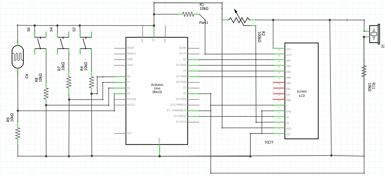
Schematic:
Arduino Code:
// include the library code:
#include <LiquidCrystal.h>

// initialize the library by associating any needed LCD interface pin
// with the arduino pin number it is connected to
const int rs = 12, en = 11, d4 = 5, d5 = 4, d6 = 3, d7 = 2;
LiquidCrystal lcd(rs, en, d4, d5, d6, d7);

int buzzerPin = 8;
int redpin = A0;
int greenpin = A1;
int bluepin = A2;
int phopin = A3;  //
float prev=0;

void setup() {
  // put your setup code here, to run once:
  pinMode(buzzerPin, OUTPUT);
  pinMode(redpin, INPUT);
  pinMode(greenpin, INPUT);
  pinMode(bluepin, INPUT);
  pinMode(phopin, INPUT);  //
  lcd.begin(16, 2);
  Serial.begin(9600);
}

void loop() {
  // put your main code here, to run repeatedly:
  int redState = digitalRead(redpin);
  int greenState = digitalRead(greenpin);
  int blueState = digitalRead(bluepin);
  int flexState = analogRead(phopin);  // 350 to 1000
  float redvariance = 130.8 + map(flexState, 350, 1050, 0, 130.8);
  float greenvariance = 261.6 + map(flexState, 350, 1050, 0, 261.6);
  float bluevariance = 523.2 + map(flexState, 350, 1050, 0, 523.2);
  if (redState == HIGH) {
    tone(buzzerPin, redvariance);
    if (higherThanPrev(prev, redvariance)) {
      lcd.print(":)");
    } else {
      lcd.print(":(");
    }
    prev = redvariance;
    delay(100);
  } else if (greenState == HIGH) {
    tone(buzzerPin, greenvariance);
    if (higherThanPrev(prev, greenvariance)) {
      lcd.print(":)");
    } else {
      lcd.print(":(");
    }
    prev = greenvariance;
    delay(100);
  } else if (blueState == HIGH) {
    tone(buzzerPin, bluevariance);
    if (higherThanPrev(prev, bluevariance)) {
      lcd.print(":)");
    } else {
      lcd.print(":(");
    }
    prev = bluevariance;
    delay(100);
  } else {
    noTone(buzzerPin);
  }
  lcd.clear();
}

bool higherThanPrev(float prev, float now) {
  return prev < now;
}
Overall we were quite pleased with the end result, even more so with our LCD addition. However, we felt as though it was difficult to classify our project as a musical instrument since, despite the complex interplay between analog/ digital sensors, the sounds produced were less “musical” in a sense.<span style=”color: #000000;”> </span><span style=”color: #000000;”>Furthermore, we realized that whilst the tone of the sound produced by the blue switch was very clearly affected by the amount of light perceived by the photoresistor, this was not the case for the red switch</span>. It was much harder to distinguish a change in the tone of the sound. We believe it is because the red button signals the C note in the 3<sup>rd</sup> octave, and the blue one signals the C note in the 5<sup>th</sup> octave. Since the frequency of octaves is calculated with the formula “Freq = note x 2<sup>N/12</sup>”, the changes in frequencies mapped to the notes will be more significant as octaves increase. For future improvements, especially with regards to its musicality, perhaps we could have each button play a series of notes, hence the 3 switches would produce a complete tune. Rather than mapping ranges for the photoresistor, we could choose a (more than/ less than) specific value. For example, in a dark room, the complete tune would be played in a lower key whilst in a bright room, the tune would play in a higher key.