I worked on this project with Akhat, and we wanted to create a tool similar to Singing Horses where each horse has its tone and frequency, can be turned on/off, and acts as an element of melody that creates a unique tune when played together with other horses. In our project, a similar idea can be seen: we have multiple buzzers each with its tune that is played when pressed on a corresponding button. One special thing about this project is that we also use a pressure sensor to change the tone just a little and create some more variation and uniqueness in each play.
Process/Challenges
We started off by testing out different parts separately – first, we got the pressure sensor working (which did not work in the beginning because of hardware, but then we switched to a different pressure sensor which worked much better). After that, when connecting buzzers and buttons, we ran into an issue where multiple buzzers were not playing at the same time. Initially, our idea was to play them simultaneously with different tunes, but apparently, Arduino does not allow that (i.e buzzers must be played one at a time). Our workaround for this problem was that instead of playing tunes simultaneously, we had them play one at a time when the switch is pressed down. Lastly, it was a lot of experimentation of what notes worked best for us given that we were changing the frequency based on the pressure sensor.
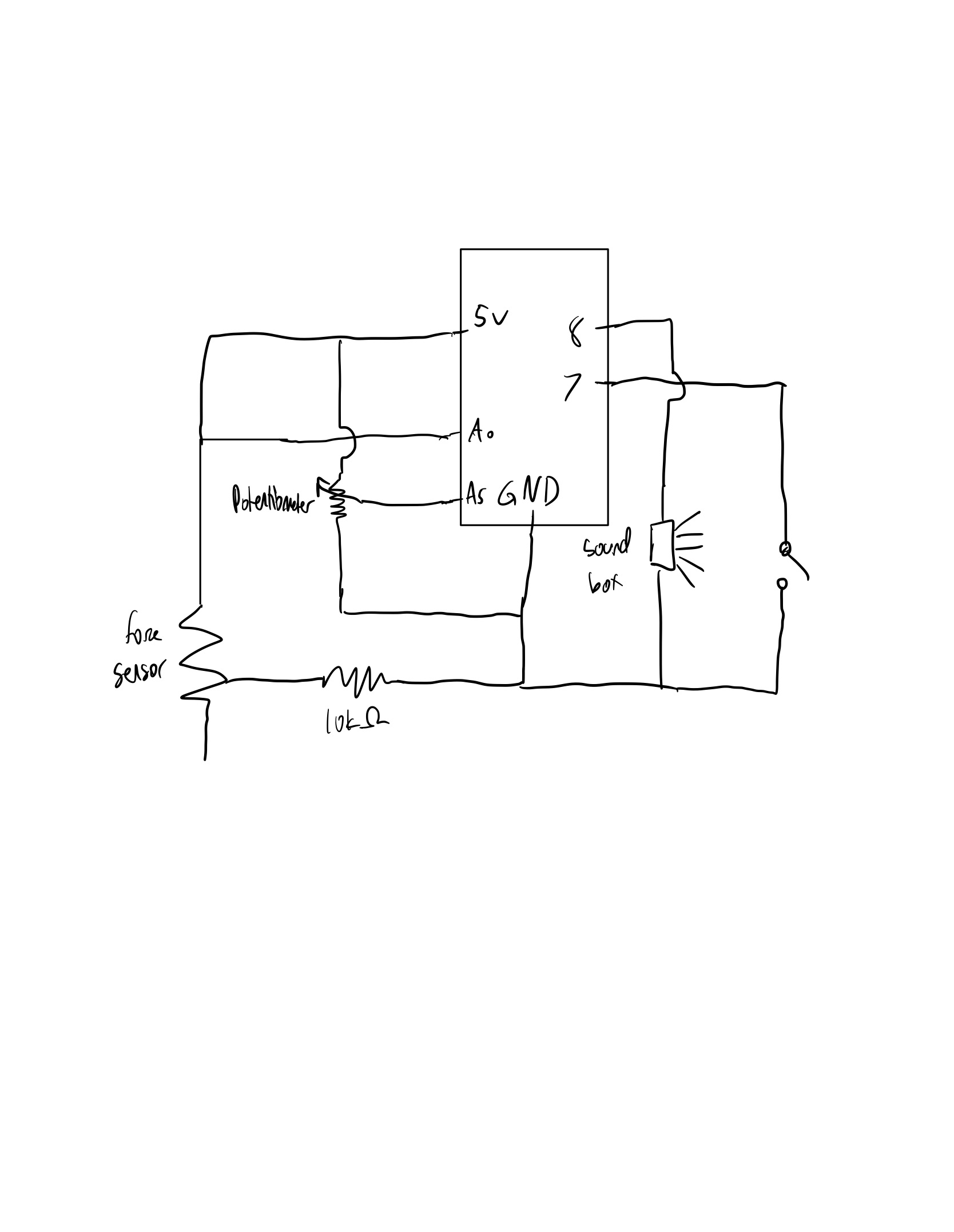
For my instrument, I used three different sensors. The force meter, potentiometer, and a switch. Originally, I wanted to read different inputs using a motor, but since I couldn’t, I used the potentiometer as the main dial that read the input to translate into pitches. The input from force meter would then decide on whether to play the notes and in which octave. The switch would change the mode of the instrument from playing designated musical notes to free range pitch.
When the switch is off, the potentiometer takes care of the main pitch from the range of notes of C to B. By turning the dial of the potentiometer from low to high, the instruments will play the notes from C to B. Then, the force meter, depending on how strong the force input is, decides on the octave of the note. For example, in my code, if force input is lower than 500 but higher than 200, it will play notes in the range of C3 to B3. All the notes are preloaded in the notes array before setup, and in this mode of the instrument, it only plays those designated musical notes. When the switch in on, the instrument will be put on a different mode where the pitch is not limited to a designated note but will be a number combined by the current potentiometer input and the force meter input. Therefore, the pitch made from this mode can be freely chosen by how strong you press the force meter and what the dial of the potentiometer is pointing at.
Circuit Diagram
Future Improvements:
In the future, I would like to use some other dial format analog sensor like the motor I initially planned. I would also think of some other creative ways to use other sensors like the bend sensor or etc.. While I used the alligator clips to incorporate the switch to my circuit, later in the future I would also like to learn soldering so I can stably add more sensors to my circuit.
For my musical instrument, I thought it would be cool to create a DJ because I wanted to try and incorporate pretty much all the components we learned up until now.
This was my idea for the components:
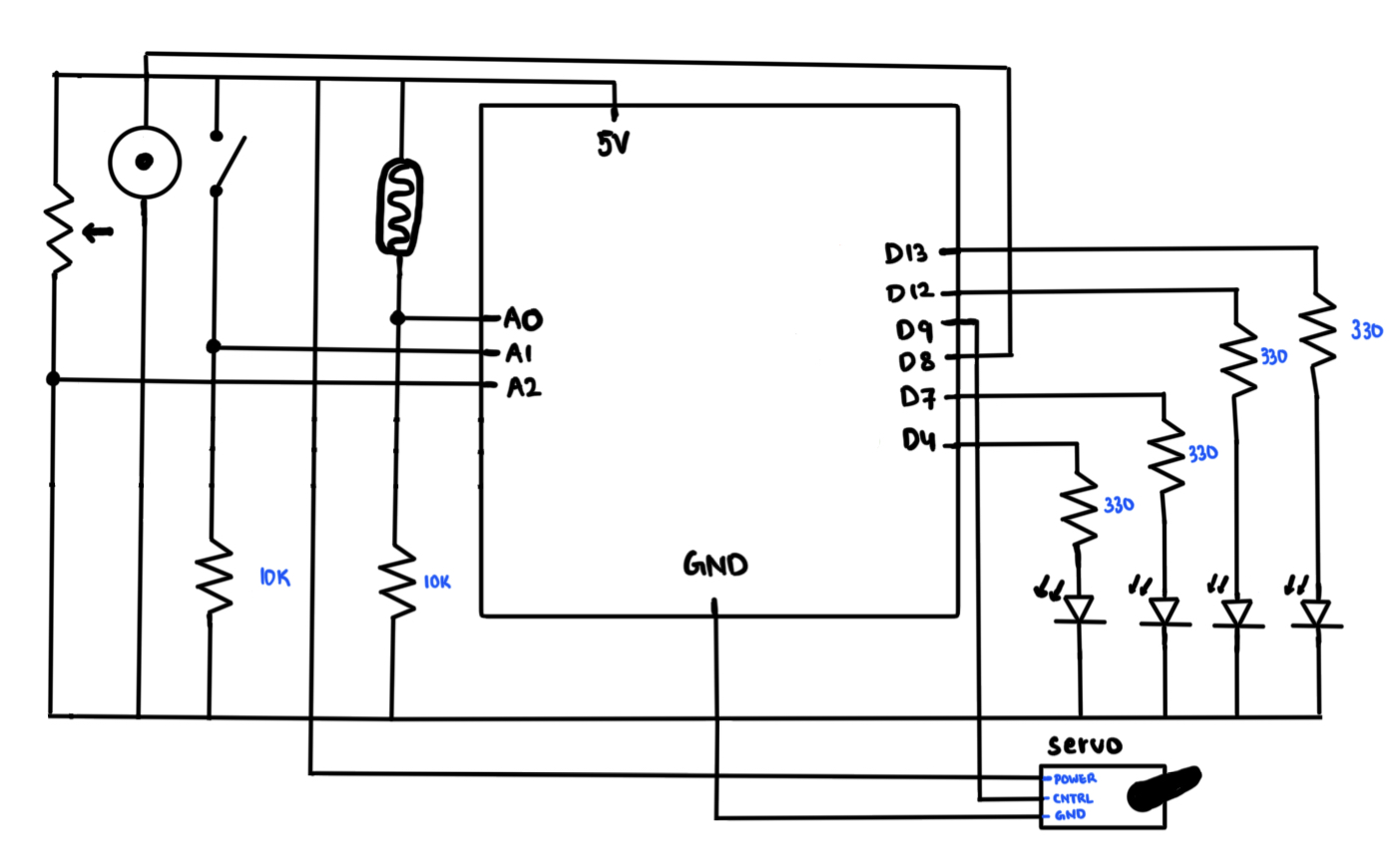
The Servo Motor could act as the DJ and this can be controlled via the light sensor. So you could move your hand up and down and it would map out the Servo rotation. Additionally, I thought it would be cool to add some cool lights to kinda give that disco vibe so as you change your hand position over the light sensor, the lights would change too.
I added a button and a potentiometer and this would essentially play the songs that a regular DJ would play. So essentially, I have a library of songs on the Arduino code, and depending on which position the potentiometer is on, when pressed the button, it would play that appropriate song.
For now, I only added 4 songs. How this worked is, I borrowed the “pitch.h” header file that we used in class to map out the note pitches and frequencies. From that, I constructed several arrays which would be the different songs. Then that would be played out loud through the buzzer.
Schematic:
Arduino Code:
#include <Servo.h>
#include "pitches.h"

const int LightSensorPin = A0;
const int PotPin = A1;
const int Button = A2;

const int ServoPin = 9;
const int BuzzerPin = 8;
const int YPin1 = 13;
const int YPin2 = 12;
const int YPin3 = 7;
const int YPin4 = 4;

const int Melody1_Size = 13;
const int Melody2_Size = 11;
const int Melody3_Size = 30;
const int Melody4_Size = 29;

Servo DJ;

//Melodies:
int melody1[] = {NOTE_E4, NOTE_D4, NOTE_FS3, NOTE_GS3, NOTE_CS4, NOTE_B3, NOTE_D3, NOTE_E3, NOTE_B3, NOTE_A3, NOTE_CS3, NOTE_E3, NOTE_A3};
int melody2[] = {NOTE_C4, NOTE_DS4, NOTE_F4, NOTE_FS4, NOTE_F4, NOTE_DS4, NOTE_C4, 0, NOTE_AS3, NOTE_D4, NOTE_C4};
int melody3[] = {NOTE_A3, NOTE_B3, NOTE_D4, NOTE_B3, NOTE_FS4, NOTE_FS4, NOTE_E4, 0, NOTE_A3, NOTE_B3, NOTE_D4, NOTE_B3, NOTE_E4, NOTE_E4, NOTE_D4, NOTE_CS4, NOTE_B3, 0, NOTE_A3, NOTE_B3, NOTE_D4, NOTE_B3, NOTE_D4, NOTE_E4, NOTE_CS4, NOTE_B3, NOTE_A3, NOTE_A3, NOTE_E4, NOTE_D4};
int melody4[] = {NOTE_E4, NOTE_D4, NOTE_C4, NOTE_D4, NOTE_E4, NOTE_E4, NOTE_E4, 0, NOTE_D4, NOTE_D4, NOTE_D4, 0, NOTE_E4, NOTE_G4, NOTE_G4, 0, NOTE_E4, NOTE_D4, NOTE_C4, NOTE_D4, NOTE_E4, NOTE_E4, NOTE_E4, NOTE_E4, NOTE_D4, NOTE_D4, NOTE_E4, NOTE_D4, NOTE_C4};

//Melody Durations
int m1_durations[] = {8, 8, 4, 4, 8, 8, 4, 4, 8, 8, 4, 4, 2};
int m2_durations[] = {4, 4, 4, 4, 4, 4, 4, 2, 8, 8, 2};
int m3_durations[] = {8, 8, 8, 8, 3, 3, 4, 3, 8, 8, 8, 8, 3, 3, 2, 8, 8, 4, 8, 8, 8, 8, 3, 3, 2, 8, 4, 4, 2, 4};
int m4_durations[] = {4, 4, 4, 4, 4, 4, 4, 4, 4, 4, 4, 4, 4, 4, 4, 4, 4, 4, 4, 4, 4, 4, 4, 4, 4, 4, 4, 4, 4};


void setup() {
  Serial.begin(9600);
  DJ.attach(ServoPin);                 //Pin for the Servo Motor

  //Analog Inputs
  pinMode(LightSensorPin, INPUT);     //Pin for the Light Sensor
  pinMode(PotPin, INPUT);             //Pin for the Potentiometer
  pinMode(Button, INPUT);             //Pin for the Button

  //LED Pins
  pinMode(YPin1, OUTPUT);
  pinMode(YPin2, OUTPUT);
  pinMode(YPin3, OUTPUT);
  pinMode(YPin4, OUTPUT);
}

void loop() {
  //Reads all the necessary values from the analog input pins
  int LightValue = analogRead(LightSensorPin);
  int PotValue = analogRead(PotPin);
  int ButtonValue = analogRead(Button);
  int discoLight = LightValue;    //Variable for changing the lights

  //Writing the Light Sensor data onto the Servo:
  LightValue = map(LightValue, 0, 1023, 0, 180);

  //Converting the potentiometer values to the according melody
  int Melody = map(PotValue, 0, 1023, 0, 4);
  DJ.write(LightValue);

  //Writing the data for the disco lights:
    if(discoLight < 550 && discoLight >= 450) {
    digitalWrite(YPin1, HIGH);
    digitalWrite(YPin2, LOW);
    digitalWrite(YPin3, LOW);
    digitalWrite(YPin4, LOW);
  }

  else if (discoLight < 450 && discoLight >= 350){
    digitalWrite(YPin1, LOW);
    digitalWrite(YPin2, HIGH);
    digitalWrite(YPin3, LOW);
    digitalWrite(YPin4, LOW);
  }

  else if(discoLight < 350 && discoLight >= 250) {
    digitalWrite(YPin1, LOW);
    digitalWrite(YPin2, LOW);
    digitalWrite(YPin3, HIGH);
    digitalWrite(YPin4, LOW);
  }

  else if(discoLight < 250) {
    digitalWrite(YPin1, LOW);
    digitalWrite(YPin2, LOW);
    digitalWrite(YPin3, LOW);
    digitalWrite(YPin4, HIGH);
  }

  //Offsets the PotValue to 3 in case it reaches 4, for stabilization
  if(PotValue == 4) {
    PotValue = 3;
  }
  Serial.println(Melody);

  //If the button is pressed, depending on the potentiometer value, it will play the according melodies.
  if(ButtonValue > 1000) {
    if(Melody == 0) {
      MelodyPlayer(melody1, m1_durations, Melody1_Size, LightValue);
    }

    else if(Melody == 1) {
      MelodyPlayer(melody2, m2_durations, Melody2_Size, LightValue);
    }

    else if(Melody == 2) {
      MelodyPlayer(melody3, m3_durations, Melody3_Size, LightValue);
    }

    else {
      MelodyPlayer(melody4, m4_durations, Melody4_Size, LightValue);
    }

  }
  delay(50);
}

//This function plays the melody that it was assigned to it. It also registers the LightValue so that way the DJ can play while the song is also playing.
void MelodyPlayer(int melodyNum[], int melodyDur[], int melodySize, int LightValue) {
    for (int thisNote = 0; thisNote < melodySize; thisNote++) {
      LightValue = analogRead(LightSensorPin);
      LightValue = map(LightValue, 0, 1023, 0, 180);
      DJ.write(LightValue);

      //To calculate the note duration, take one second divided by the note type.
      //Ex: quarter note = 1000 / 4, eighth note = 1000/8, etc.
      int noteDuration = 1000 / melodyDur[thisNote];

      tone(8, melodyNum[thisNote], noteDuration);
      //To distinguish the notes, set a minimum time between them.
      int pauseBetweenNotes = noteDuration * 1.30;
      delay(pauseBetweenNotes);

      //Stop the tone playing:
      noTone(8);
    }
}
Video:
Improvements:
I feel that when the song is playing, because it enters the for loop, the sensors stop reading in data, meaning the servo motors and the LED lights stop reading in data so it won’t move while the song is playing. My solution was to pass the LightValue so that the motor would at least move while the song is playing on beat. But if the motor and lights could move while the song is playing freely like it does with no song playing, that would be an amazing improvement.
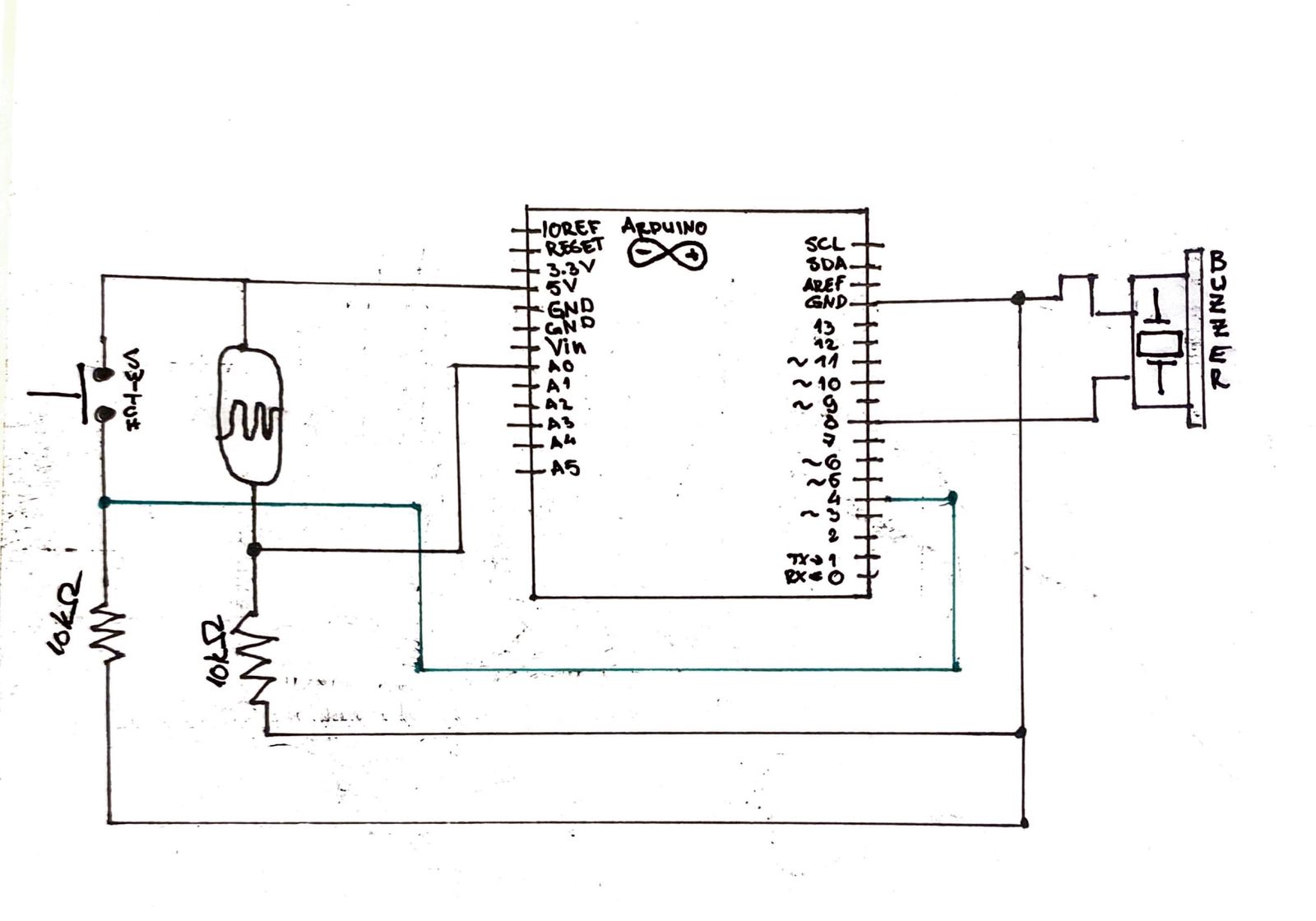
For this assignment, we wanted to create a version “Theremin” that will be linked with the light sensor and will produce sound based on the light intensity received by the sensor on Arduino board. Additionally, we’ll add the switch to this Light Theremin to change the frequency of the sound and to play different sounds using the light sensor. The frequency only changes while the button is pressed, we did this to change tune while playing the theremin which makes it easier for the user to play different tone from both frequencies. In short, the analog in takes values from the light sensor and these values are converted within a certain limit to be played through the buzzer. When the button is pressed, the limit of these values changes and thus giving us the tone of higher frequency.
SCHEMATIC: Video:
Code:
// create variable to hold sensor value
int sensorValue;
// UNO's analog read sensors use "analog to digital converter" (ADC),
// which means it divides the reading coming from the sensor (0 to 5 volts) into 1024 equal steps.
// Thus, the reading from our photoresistor could range from 0 to 1023,
// however it is unlikely to use the full range so we will calibrate it.
// For now, create variables to hold the high and low value for our photoresistor range,
// make them the opposite of the max/min values and we will calibrate them down.
int sensorLow = 1023;
int sensorHigh = 0;
// set the LED pin, 13 is the built in LED
const int ledPin = 13;
int switchFreq = 4;
int switchVal;


void setup() {


  pinMode(ledPin, OUTPUT);
  pinMode(switchFreq, INPUT);

  digitalWrite(ledPin, HIGH);

  delay(500);

  digitalWrite(ledPin, LOW);
  delay(500);
  digitalWrite(ledPin, HIGH);
  delay(500);
  digitalWrite(ledPin, LOW);
  delay(500);
  digitalWrite(ledPin, HIGH);

  // after it blinks for 2 seconds, its time to calibrate the photoresistor readings
  // create a loop with while() that lasts for 5000 ms to calibrate the light sensor according the setting,
  while (millis() < 5000) {
    // use analogRead() to get a reading from the photoresistor,
    sensorValue = analogRead(A0);
    // create two conditions using if() to calibrate the max and min sensor values,
    // raise the sensorHigh if the current reading is higher:
    if (sensorValue > sensorHigh) {
      sensorHigh = sensorValue;
    }
    // lower the sensorLow if the current reading is lower:
    if (sensorValue < sensorLow) {
      sensorLow = sensorValue;
    }
  }

  // turn the LED off, calibration is done!
  digitalWrite(ledPin, LOW);
}


void loop() {
  //read the input from A0 and store it in a variable
  sensorValue = analogRead(A0);
  switchVal = digitalRead(switchFreq);

  // map(currentValue, oldRange1, oldRange2, newRange1, newRange2)
  // I reverse their order (high, low) so that shading the photoresister will cause a higher tone.
  // the new range is the range of Hz to use to produce sound, which for UNO can be from 31 to 65535 Hz.
  // I set it from 0 to 300, which is a more normal sound range and if a button is pressed I change the values between 500 to 1000
  // since we start at 0, full light will make no tone, full shade will make the highest tone.
  if (switchVal == HIGH){
  int pitch = map(sensorValue, sensorHigh, sensorLow, 500, 1000);
  tone(8, pitch, 10);
  }
  else{
    int pitch = map(sensorValue, sensorHigh, sensorLow, 0, 300);
    tone(8, pitch, 10);
  }
  // use the tone function to create sound in the piezo,
  // tone(pin#, value, milliseconds)


  // add a delay to make the current tone sustained for a few ms to adjust the quality of the tone
  delay(15);
}
Future improvements:
For future, we want to use more than 2 limits of frequencies and we want to add instruments that could be switched using the button. After completing this project, we realised that playing sound using the light sensor is easier than any other sensor since it only requires basic movements of hands to block the light or allow the light to the sensor. Thus, in future, we’d like to add more instruments like electric guitar frequencies and allow users to switch between these instruments using the switch buttons.
Concept:
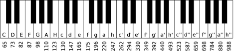
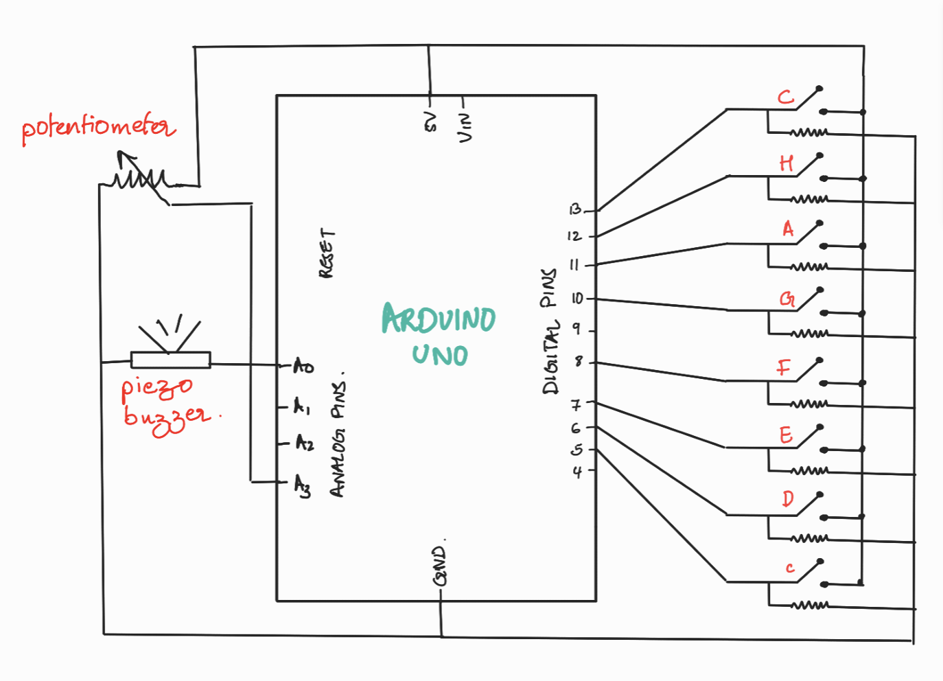
After going over several examples of musical instruments that we could create using the specified digital and analog sensors, Sanjana Nambiar and I decided to settle on the old but gold piano. The concept behind our project is simple and straightforward: our piano will consist of 8 buttons that will correspond to piano tiles and the buzzer will play a corresponding musical note when the user presses one of the eight switch buttons. We integrated an analog input to our project by getting the value from the potentiometer and mapping it to one of the four octaves. Based on this mapping, the button will play different variations of the same note i.e. A or a or a’ or a’’. Below is the illustration of the four octaves that we used and the corresponding notes and frequencies.
Code:
// arduino-equivalent frequencies of the musical notes for each tile of the piano
// each note is stored in a list consisitning of three other notes of  different pitch
int T_C[4] = {65, 130, 262, 523};
int T_D[4] = {73, 147, 294, 587};
int T_E[4] = {82, 165, 330, 659};
int T_F[4] = {87, 175, 349, 698};
int T_G[4] = {98, 196, 392, 784};
int T_A[4] = {110, 220, 440, 880};
int T_H[4] = {123, 247, 493, 988};
int T_c[4] = {130, 262, 523, 1046};

//names of each tile and the corresponding digital  pins
const int A = 11;
const int C = 5;
const int D = 6;
const int E = 7;
const int F = 8;
const int G = 10;
const int H = 12;
const int c = 13;

const int Buzz = A0;

void setup()
{
  Serial.begin(9600);

  //declare the switches as digital input devices
  pinMode(C, INPUT);
  pinMode(D, INPUT);
  pinMode(E, INPUT);
  pinMode(F, INPUT);
  pinMode(G, INPUT);
  pinMode(A, INPUT);
  pinMode(H, INPUT);
  pinMode(c, INPUT);
}

void loop()
{
  //read the analog input from the potentiometer
  int potPosition = analogRead(A3);

  //map that input to the the value in the range 0-4
  potPosition = map(potPosition, 0, 1023, 0, 4);
  Serial.println(potPosition);

  //value 4 is just a dummy value that will be used to detect the end of the potentiometer,
  //so when we get value 4 from the poentiometer, we treat it as 3
  if(potPosition == 4){ potPosition = 3; }

  //play the correspondting tone for each of the 8 swithces
  while(digitalRead(C) == HIGH){ tone(Buzz,T_C[potPosition]); }
  while(digitalRead(D) == HIGH){ tone(Buzz,T_D[potPosition]); }
  while(digitalRead(E) == HIGH){ tone(Buzz,T_E[potPosition]); }
  while(digitalRead(F) == HIGH){ tone(Buzz,T_F[potPosition]); }
  while(digitalRead(G) == HIGH){ tone(Buzz,T_G[potPosition]); }
  while(digitalRead(A) == HIGH){ tone(Buzz,T_A[potPosition]); }
  while(digitalRead(H) == HIGH){ tone(Buzz,T_H[potPosition]); }
  while(digitalRead(c) == HIGH){ tone(Buzz,T_c[potPosition]); }

  noTone(Buzz);
}
Schematic:
Demo:
Future Improvements
Since we were limited in the use of sensors that we could use, our piano doesn’t really look like a real-world piano. So, one of the improvements we could make is to create a separate portable piano i.e. a cardboard piano covered with aluminum foil or equipped with force sensors, and adapt our code to play the same sounds when the corresponding tile will get pressed. We could also work on implementing the logic to handle the case when two tiles are pressed simultaneously.
After going over several examples of musical instruments that we could create using the specified digital and analog sensors, Sanjana Nambiar and I decided to settle on the old but gold piano. The concept behind our project is simple and straightforward: our piano will consist of 8 buttons that will correspond to piano tiles and the buzzer will play a corresponding musical note when the user presses one of the eight switch buttons. We integrated an analog input to our project by getting the value from the potentiometer and mapping it to one of the four octaves. Based on this mapping, the button will play different variations of the same note i.e. A or a or a’ or a’’. Below is the illustration of the four octaves that we used and the corresponding notes and frequencies.
Code
// arduino-equivalent frequencies of the musical notes for each tile of the piano
// each note is stored in a list consisitning of three other notes of  different pitch
int T_C[4] = {65, 130, 262, 523};
int T_D[4] = {73, 147, 294, 587};
int T_E[4] = {82, 165, 330, 659};
int T_F[4] = {87, 175, 349, 698};
int T_G[4] = {98, 196, 392, 784};
int T_A[4] = {110, 220, 440, 880};
int T_H[4] = {123, 247, 493, 988};
int T_c[4] = {130, 262, 523, 1046};

//names of each tile and the corresponding digital  pins
const int A = 11;
const int C = 5;
const int D = 6;
const int E = 7;
const int F = 8;
const int G = 10;
const int H = 12;
const int c = 13;

const int Buzz = A0;

void setup()
{
  Serial.begin(9600);

  //declare the switches as digital input devices
  pinMode(C, INPUT);
  pinMode(D, INPUT);
  pinMode(E, INPUT);
  pinMode(F, INPUT);
  pinMode(G, INPUT);
  pinMode(A, INPUT);
  pinMode(H, INPUT);
  pinMode(c, INPUT);
}

void loop()
{
  //read the analog input from the potentiometer
  int potPosition = analogRead(A3);

  //map that input to the the value in the range 0-4
  potPosition = map(potPosition, 0, 1023, 0, 4);
  Serial.println(potPosition);

  //value 4 is just a dummy value that will be used to detect the end of the potentiometer,
  //so when we get value 4 from the poentiometer, we treat it as 3
  if(potPosition == 4){ potPosition = 3; }

  //play the correspondting tone for each of the 8 swithces
  while(digitalRead(C) == HIGH){ tone(Buzz,T_C[potPosition]); }
  while(digitalRead(D) == HIGH){ tone(Buzz,T_D[potPosition]); }
  while(digitalRead(E) == HIGH){ tone(Buzz,T_E[potPosition]); }
  while(digitalRead(F) == HIGH){ tone(Buzz,T_F[potPosition]); }
  while(digitalRead(G) == HIGH){ tone(Buzz,T_G[potPosition]); }
  while(digitalRead(A) == HIGH){ tone(Buzz,T_A[potPosition]); }
  while(digitalRead(H) == HIGH){ tone(Buzz,T_H[potPosition]); }
  while(digitalRead(c) == HIGH){ tone(Buzz,T_c[potPosition]); }

  noTone(Buzz);
}
Schematic
Demo
Future Improvements
Since we were limited in the use of sensors that we could use, our piano doesn’t really look like a real-world piano. So, one of the improvements we could make is to create a separate portable piano i.e. a cardboard piano covered with aluminum foil or equipped with force sensors, and adapt our code to play the same sounds when the corresponding tile will get pressed. We could also work on implementing the logic to handle the case when two tiles are pressed simultaneously.
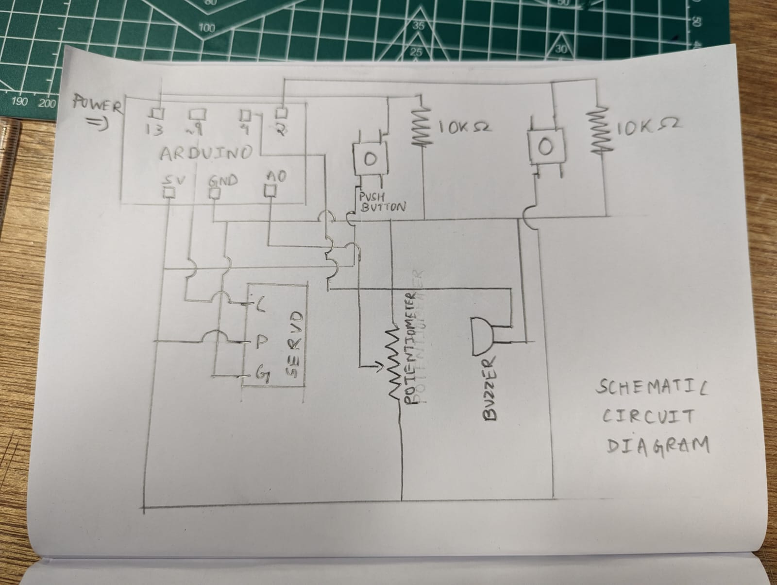
This week’s assignment was to create a simple musical instrument using the Arduino. Hana and Ajla decided to create a simplified piano and drum. In order to do so, we utilized switches and a servo motor. We controlled the speed of the servo motor using a potentiometer. The notes are played by pressing the buttons. The buttons stop producing noise when released.
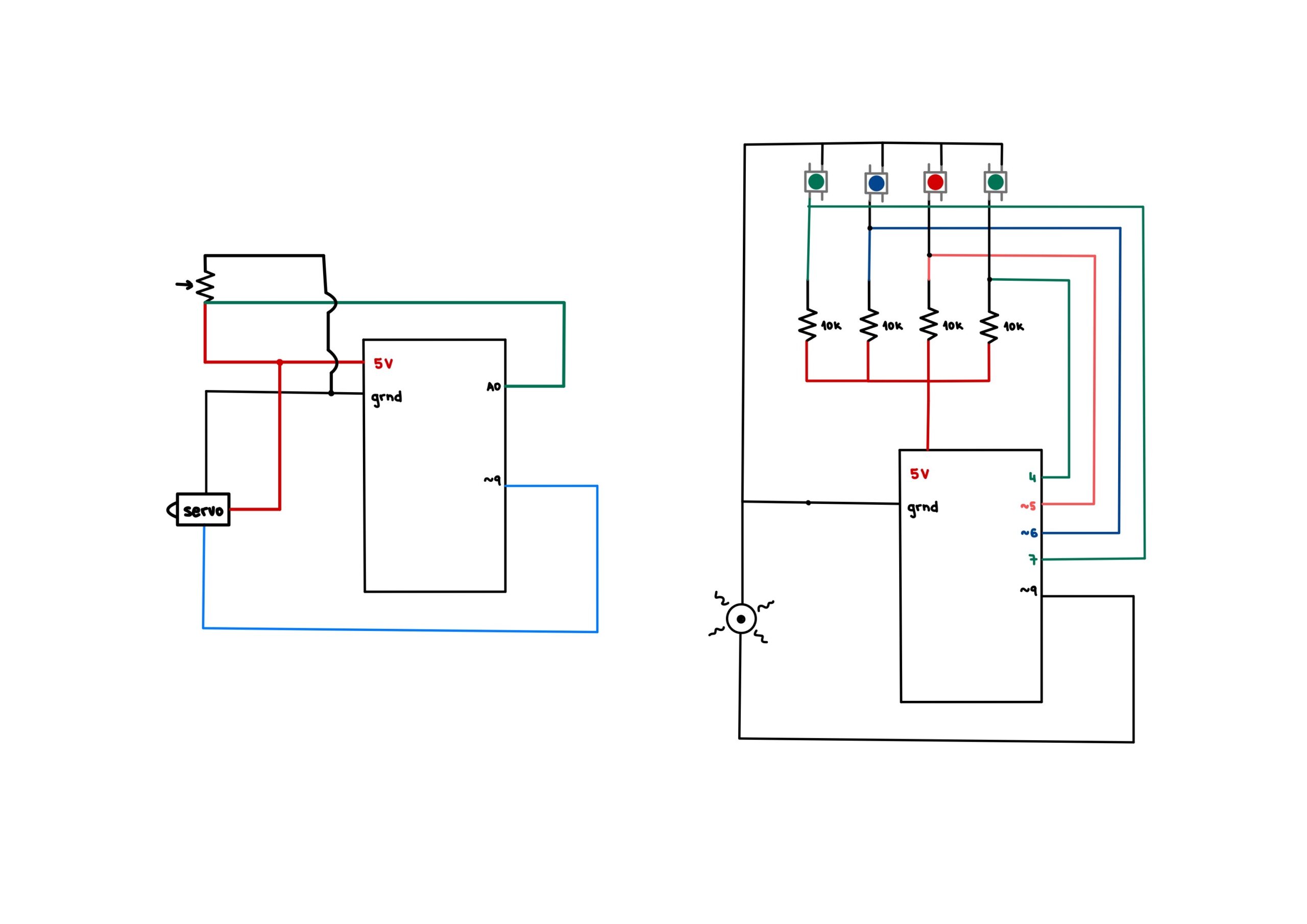
Servo circuit
Implementation
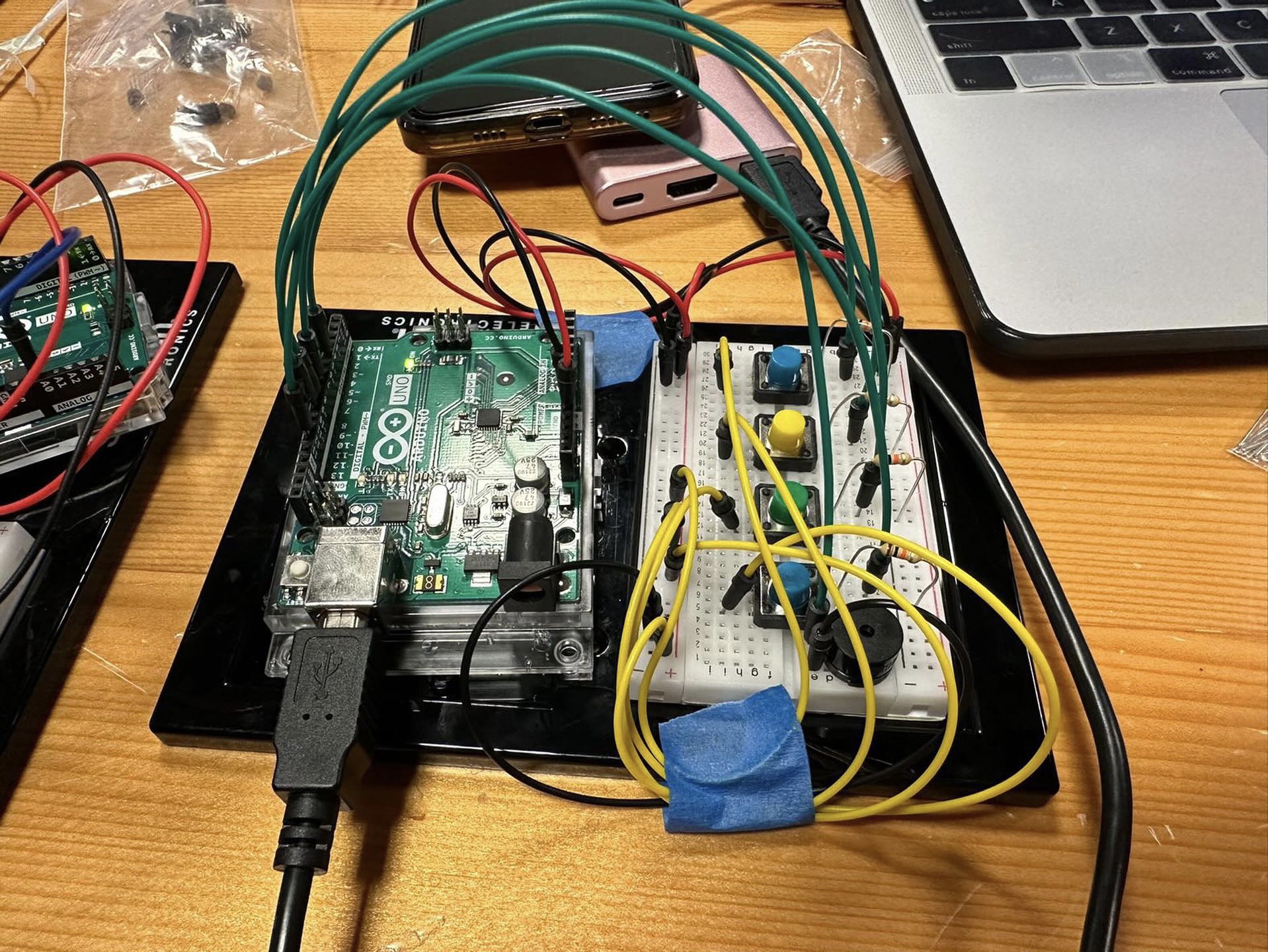
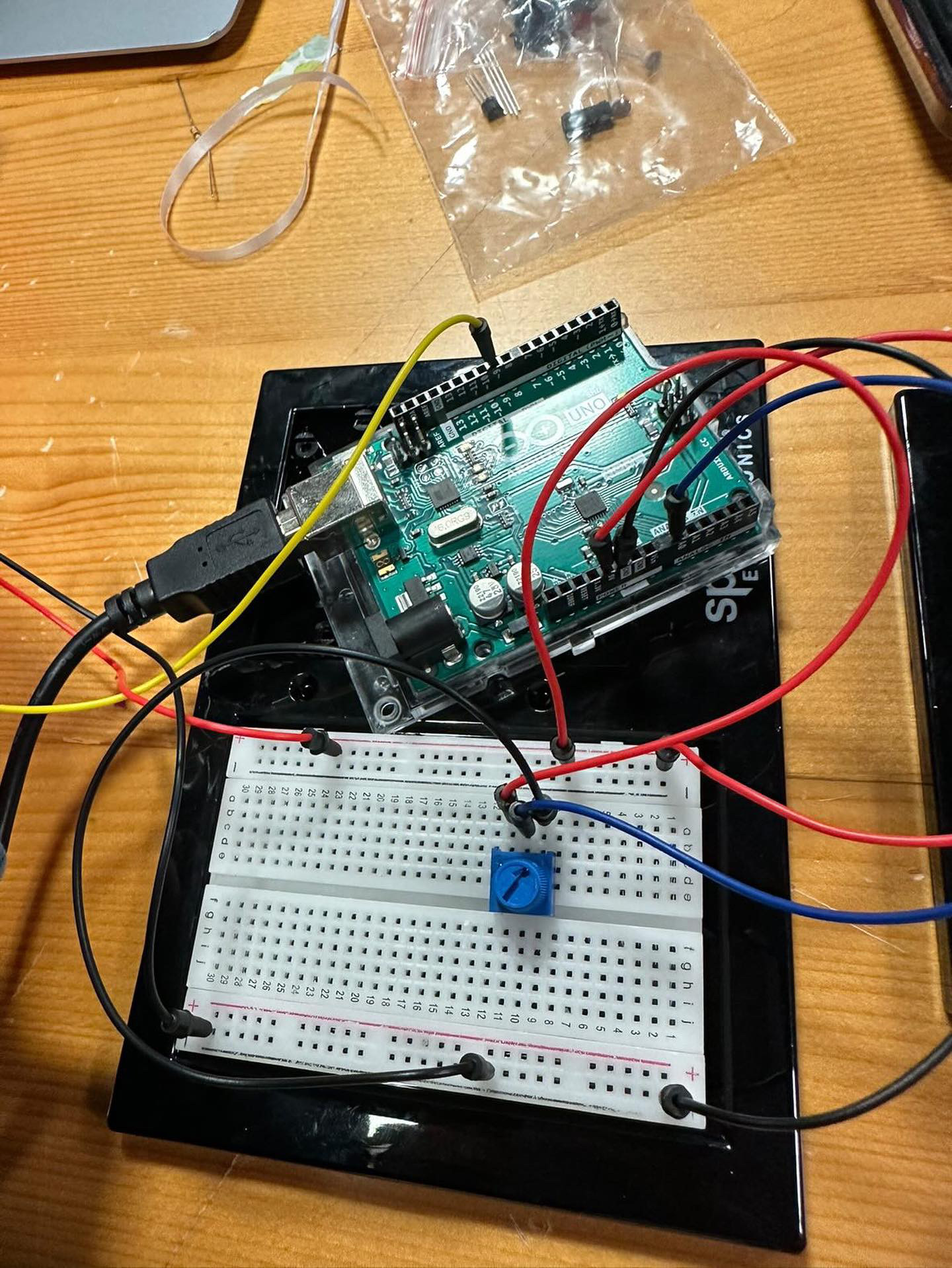
To implement our musical instrument, we used a potentiometer, switches, a piezoelectric buzzer, resistors, wires and an Arduino. By connecting the switches in parallel we were able to preserve voltage across all components. Even though it was possible to connect everything on one breadboard, we decided to separate it in order to make the instrument user friendly. Furthermore, since many digital inputs were used, the separation ensured that there would not be any overcrowding while presenting the final product.The sketches below show both the two Arduino setup we used and one Arduino setup.
The code was written for both Arduino. Hana wrote the code for the switches and Ajla wrote the code for the drum. The drum was made using a metal screw, silk ribbon and tape which was attached to the servo hand. By pressing the four switches, notes, stored in an array, were played. The drum hit a piece of cardboard in order to produce noise.
Two ArduinoOne Arduino
Here is the code for playing the notes:
// if button1 is pressed, plays first note
  if(button1State==1) {
    tone(9, notes[0]);
  }

// if button2 is pressed, plays second note

  if(button2State==1) {
    tone(9, notes[1]);
  }

// if button3 is pressed, plays third note

  if(button3State==1) {
    tone(9, notes[2]);
  }

// if button4 is pressed, plays fourth note

  if(button4State==1) {
    tone(9, notes[3]);
  }

// if buttons are release, no note is played

  if(button1State==0 && button2State==0  && button3State==0 && button4State==0) {
    noTone(9);
  }


  delay(1);  // delay in between reads for stability
Here is the code that ran the servo in a 90 degree range:
void loop() {
  int p_value  = analogRead(p_meter);

  int value = map(p_value, 0, 1024, 10, 20);
  for (int i=45; i<90; i += value) {
    pos1 = 0 + (i*2);          // servo1 from 0 to 90 degrees
    myservo1.write(pos1);      // move the servo
    delay(50);
  }

  for (int i=45; i<90; i += value) {
    pos1 = 90 - i*2;           // servo1 from 90 to 0 degrees
    myservo1.write(pos1);      // move the servo
    delay(50);
  }
}
Challenges
The assignment came with a few challenges. Firstly, since the piezoelectric buzzer cannot take multiple inputs at once, it was important to play each note once, without pressing others since that would destroy the quality of the sound. Secondly, the notes play continuously if the button is pressed, even once. That is why we added the last if statement that checks whether all buttons are not pressed, in which case it plays no sound. Thirdly, the servo is quite tricky to use at high speeds. It gets more imprecise as the speed goes up. So, controlling it with the potentiometer was quite hard to do precisely. Lastly, since the angle of motion changes as the speed increases, it was hard to mount the servo on anything as it would immediately fall down once the speed was changed. This became quite frustrating that we decided to just hold the servo in the end to showcase the tempo of the “drum”. All in all, this assignment came with quite a few challenges. Some of them we tried to attempt and won, such as the notes, but some of them remain to be defeated due to the lack of time and materials we had at the time of making this project.
Reflection
Our team went back and forth on ideas on what to do as an instrument because neither of us are musically inclined. However, we landed on this idea after a few iterations. We struggled quite a bit to get everything right, as was mentioned in the challenges above, but we overcame them with solutions such as only playing one note at a time, and having to hold the servo since it would not stay mounted. Overall, it was a great learning experience, but I realized that for the final project I will most probably not delve into anything sound or music related since my creativity is a lot more limited.
For this project, I really wanted to make use of the servo motor in some way to produce sound. After fiddling around for quite some time, I found that the lid of my scented candle was the right place to put the motor. I noticed that it made an interesting sound when it dragged against the lid. This, along with an LDR, pushbutton, and sonar sensor are what I used to create my musical instrument.
Implementation
I wanted some way to control the speed at which the servo motor operated to produce a different background noise that the user could control. I also wanted to make it as convenient as possible for the user to operate it since the other hand was supposed to move in front of the sonar sensor to produce notes. So I decided to use an LDR sensor to control the servo motor’s speed. The brighter it gets, the greater the speed of the motor. Since I wanted to make it convenient, I used my phone’s torch and varied its brightness from a distance to control the speed of the motor. In the meanwhile, my other hand controlled the different notes that were being played on the buzzer.
I used an array of notes to store the different tones I was going to play based on the user’s hand position. The distance from the sensor was mapped to the indices of the notes array.
I also made use of a pushbutton to turn the motor off if the user wanted to. While the button is pressed, the motor won’t run. I did this because the other way around would have been to press the button to make the motor run, which would have been inconvenient for the user since they also have to use the light at the same time to control the motor’s speed.
The code I used for this project can be found below:
#include <Servo.h>

Servo myservo;  // create servo object to control a servo
// twelve servo objects can be created on most boards

int pos = 0;    // variable to store the servo position
int servoSpeed = 2; // variable to change servo speed based on light

// variables for sonar sensor
int trig = 10;
int echo = 11;
long duration;
long distance;

// variable for pushbutton position
int buttonPin = 2;
// variable for button HIGH or LOW
int buttonState = 0;

void setup() {
  // attaches the servo on pin 9 to the servo object
  myservo.attach(9);
  // setting the echo and trig pins of the sonar sensor
  pinMode(echo, INPUT);
  pinMode(trig, OUTPUT);
  // setting up the pushbutton
  pinMode(buttonPin, INPUT);
  Serial.begin(9600); // for debugging
}

void loop() {
  // read the state of the pushbutton value:
  buttonState = digitalRead(buttonPin);
  // Serial.println(buttonState);

  //getting distance from the sonar sensor
  digitalWrite(trig, LOW);
  delayMicroseconds(2);
  digitalWrite(trig, HIGH);
  delayMicroseconds(10);
  digitalWrite(trig, LOW);
  duration = pulseIn(echo, HIGH);
  distance = (duration / 2) * 0.0344;

  // creating an array of frequencies
  // int notes[7] = {261, 294, 329, 349, 392, 440, 494};
  int notes[7] = {523, 587, 659, 698, 784, 880, 988};

  // if the hand is away from the sonar sensor
  if (distance < 0 || distance > 30) {
    // mute the sound
    noTone(12);
  }

  // else play the tones
  else {
    // map the distance of the hand to the indices of the notes array
    int sound = map(distance, 0, 30, 0, 6);
    // play the specific note
    tone(12, notes[sound]);
  }

  // reading from the LDR
  int sensorValue = analogRead(A0);
  // Serial.println(sensorValue);
  // // delay(1);

  // setting the speed of the servo motor based on light intensity
  if (sensorValue < 102) {
    servoSpeed = 1;
  }
  else if (sensorValue < 130) {
    servoSpeed = 2;
  }
  else {
    servoSpeed = 3;
  }

  // making the servo motor move
  if (buttonState == LOW) {
    for (pos = 0; pos <= 180; pos += 1) { // goes from 0 degrees to 180 degrees
      // in steps of 1 degree
      myservo.write(pos); // tell servo to go to position in variable 'pos'
      delay(servoSpeed);  // waits 15ms for the servo to reach the position
    }
    for (pos = 180; pos >= 0; pos -= 1) { // goes from 180 degrees to 0 degrees
      myservo.write(pos); // tell servo to go to position in variable 'pos'
      delay(servoSpeed);  // waits 15ms for the servo to reach the position
    }
  }
}
Challenges
The most challenging aspect for me in this project was to decide how to make the instrument operate. The decision to use the LDR to control the motor’s speed, making use of the pushbutton to control whether the motor was running or not, and using the sonar sensor instead of something like a potentiometer. Making the instrument work is one aspect, but putting everything together in a logical manner that would be easy enough to operate and at the same time sound decent enough was somewhat challenging. Nevertheless, I learned a lot about the piezo buzzer and producing sounds in general using the Arduino in this homework, and it was fun to do.
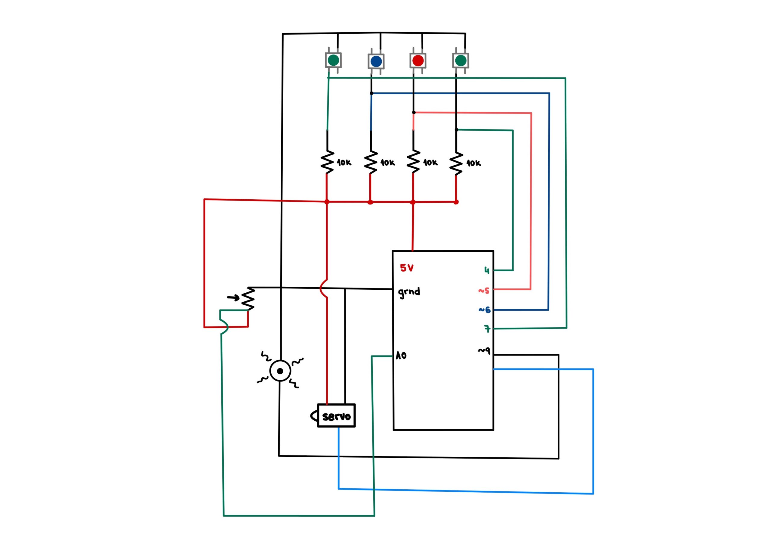
The inspiration for this project comes from a DJ controller. We wanted to design a physical interface that would allow a range of motions by the DJ. Our focus was on an easy and intuitive design that would mimic a basic DJ controller. The 2 requirements that had to be fulfilled were a beat-making mechanism as well as a musical mechanism in which the frequency can be controlled.
Concept
In order to make our inspiration become a reality, we have decided to produce the musical notes in different frequencies of 7 tones through the buzzer while making a beat maker using the servo. A push button connected to the servo slams the handle on the wooden surface imitating the beat sound. On the other side, another button is used to switch between 7 different notes that are played in the buzzer. Potentiometer that feeds back to the buzzer allows the frequency of the tone that the buzzer is playing to go higher when it is twisted right, and lower when twisted left.
Implementation
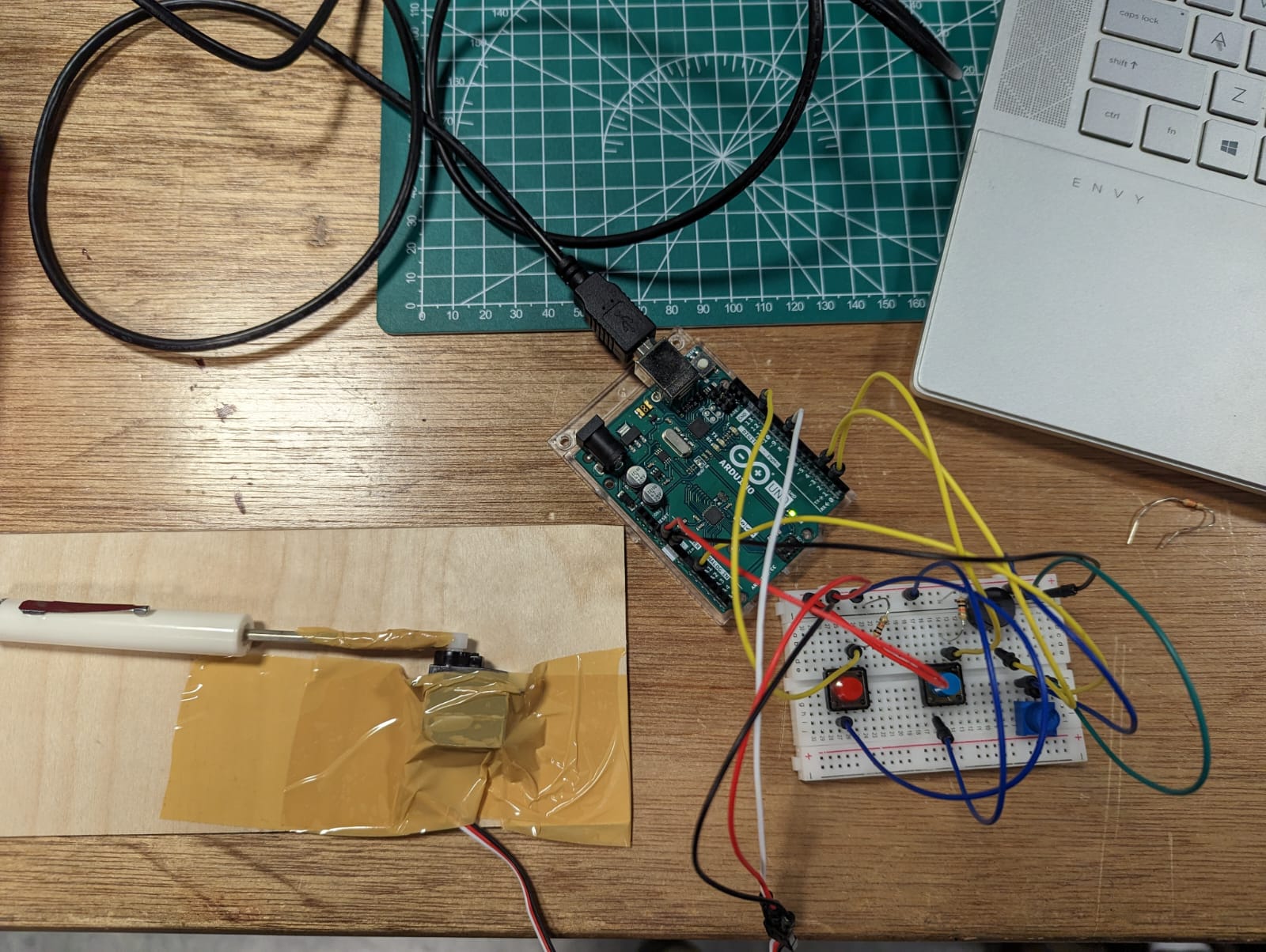
In the implementation of the project an Arduino Uno, a servo, 2 push buttons, a buzzer, and a potentiometer are used. Servo’s rotating wing is taped to plastic handled screwdriver while the servo itself is fixed on a wooden plate.
The first push-button retains information on the occasions where it is pressed. A push that is recorded prompts the screwdriver that is connected to the rotating wing of the servo to switch from a levitating position to slam on the wooden fixation plate. The sound produced is similar to a beat sound that can be achieved from an electronic device. On the other side of the board, the push button and potentiometer both record information that changes the state of the buzzer. The buzzer is constantly creating sound. The range of sound is modeled from a piano’s octaves, and therefore there are 7 keys in 7 different octaves that can be produced from this buzzer according to the code. The frequencies of these notes are numerically written into the notes double array. The push button for the buzzer (stationed towards the right side of the breadboard) switches between the 7 notes in the order of B, C,D,E,F,G, and A. Potentiometer on the other hand, switches into higher pitch/frequency of the same note, visually can be thought of as higher octave of the same note on the piano, when turned towards the right. There are again 7 octaves possible, in which the most left position of the potentiometer is the lowest frequency the note exists in while the most right position is the highest frequency of the note.
This is the code for the said implementation.
//Include Servo Library
#include <Servo.h>

//servo
int servoPin = 9;
int pos1 = 40;
int pos2 = 110;
int dt = 100;
Servo myServo;


//pushButton for servo
int pbPin = 13;
bool pbFlag = true;

//pushButton for note change
int notePin = 2;
bool nbFlag = true;
int currNoteI = 0;
int mappedValue;

//potentiometer
int potPin = A0;

//notes array
int tones[7][7] = {{31, 62, 123, 494, 988, 1976, 3951}, {33, 65, 131, 262, 523, 1047, 2093}, {37, 73, 147, 294, 587, 1175, 2349}, {41, 82, 165, 330, 659, 1319, 2637},
  {44, 87, 175, 349, 698, 1397, 2794}, {49, 98, 196, 392, 784, 1568, 3136}, {55, 110, 220, 440, 880, 1760, 3520}
};

//buzzer
int tonePin = 4;

void moveServo() {
  delay(dt);
  myServo.write(pos1);
  delay(dt);
  myServo.write(pos2);
  delay(dt);
}

void setup() {
  // put your setup code here, to run once:
  Serial.begin(9600);

  //  setting up servos
  myServo.attach(servoPin);
  myServo.write(pos2);

  //  setting up pushbutton
  pinMode(pbPin, INPUT);

  //  setting up buzzer
  pinMode(tonePin, OUTPUT);


}

void loop() {
  // put your main code here, to run repeatedly:
  //pushbutton and servo implementation
  int pbVal = digitalRead(pbPin);
  if (pbVal == 1 && pbFlag) {
    //high
    moveServo();
    pbFlag = false;
  }
  else if (pbVal == 0) {
    pbFlag = true;
  }

  //potentiometer implementation
  int potValue = analogRead(potPin);
  mappedValue = map(potValue, 0, 1023, 6, -1);
  //  Serial.println(mappedValue);
  //  Serial.println(potValue);

  //  pushbutton and note change implementation
  int nbVal = digitalRead(notePin);
  if (nbVal == 1 && nbFlag) {
    //high
    if (currNoteI < 6) {
      currNoteI++;
    }
    else {
      currNoteI = 0;
    }
    Serial.print("The current note is: ");
    Serial.println(currNoteI);
    nbFlag = false;
  }
  else if (nbVal == 0) {
    nbFlag = true;
  }

  //buzzer
  tone(tonePin, tones[currNoteI][mappedValue]);

}
Schematic Diagram
Challenges
The main challenge that we have come across was making the location of the push buttons and the potentiometer user-friendly while taking wires into consideration. We had to play around with different versions of the breadboard construction multiple times to make sure the musical instrument was approachable and easy to use.
Moreover, we also considered multiple circuit designs for the buzzer in order to control the volume by adding resistors. Upon multiple trials, we have decided not to add a resistor for maximum volume and clarity.
For servo attachment, we looked around for a considerable time to find the most suitable extension to make the optimum beat sound. Before deciding on attaching the screwdriver to the rotational component of the servo, we considered using plastic and wooden extensions. For gaining the right sound of a beat, we realized we needed more weight for the attached piece, hence the final screwdriver extension was chosen. Putting a wooden plate below enhanced the experience, after our trial and error.
Another consideration was given to the response time of the servo, by adjusting the delay time in the moveServo() function. The final adjusted value of the delay was given according to what sounded natural according to the frequency at which the push button of the servo was pushed.
Reflections
Making this project together as a group was very enjoyable, which made the design process more exciting and fun. A part to improve on in the next projects would be in terms of having more power in choosing which tone to play on the buzzer rather than having to follow the set order that is programmed in the current version of the code. On a more general note, we would love to improve our ability to follow up what is happening in the circuit as it gets more complex, and making the schematic together definitely allowed us to work on that.
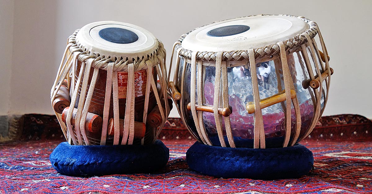
Saamia and I created a unique version of the tabla, a pair of hand drums commonly used in traditional South Asian music.
Initially, we thought of recreating the same instrument with the use of pressure sensor resistors but then we decided to make it light-sensitive. Our vision was to make the tabla come alive with an ethereal quality, allowing it to be played not by hand, but by the interaction of light. It was an interesting and fun project that resulted in a unique musical instrument.
Initially, we began the project by connecting a single light sensor to a speaker. The main challenge we encountered was mapping the readings from the light sensor to play the correct melody from an array of notes. During the process of setting these thresholds, we decided to make the instrument turn off in bright conditions and start playing sound when the light sensor was covered by a hand in dimmer conditions. This approach created a similar hand action to that of hitting the tabla with the hand, resulting in a more authentic and natural playing experience.
After the initial phase, we decided to expand our project by adding another light sensor to take readings of the surrounding light. However, we faced a challenge when we realized that the changes in light conditions on the two light sensors were not being accurately reflected by the single speaker we were using. To solve this issue, we decided to divide the instrument into two separate speakers, with each speaker connected to one light sensor individually. This allowed for more distinct and clear sound production based on the readings of each light sensor.

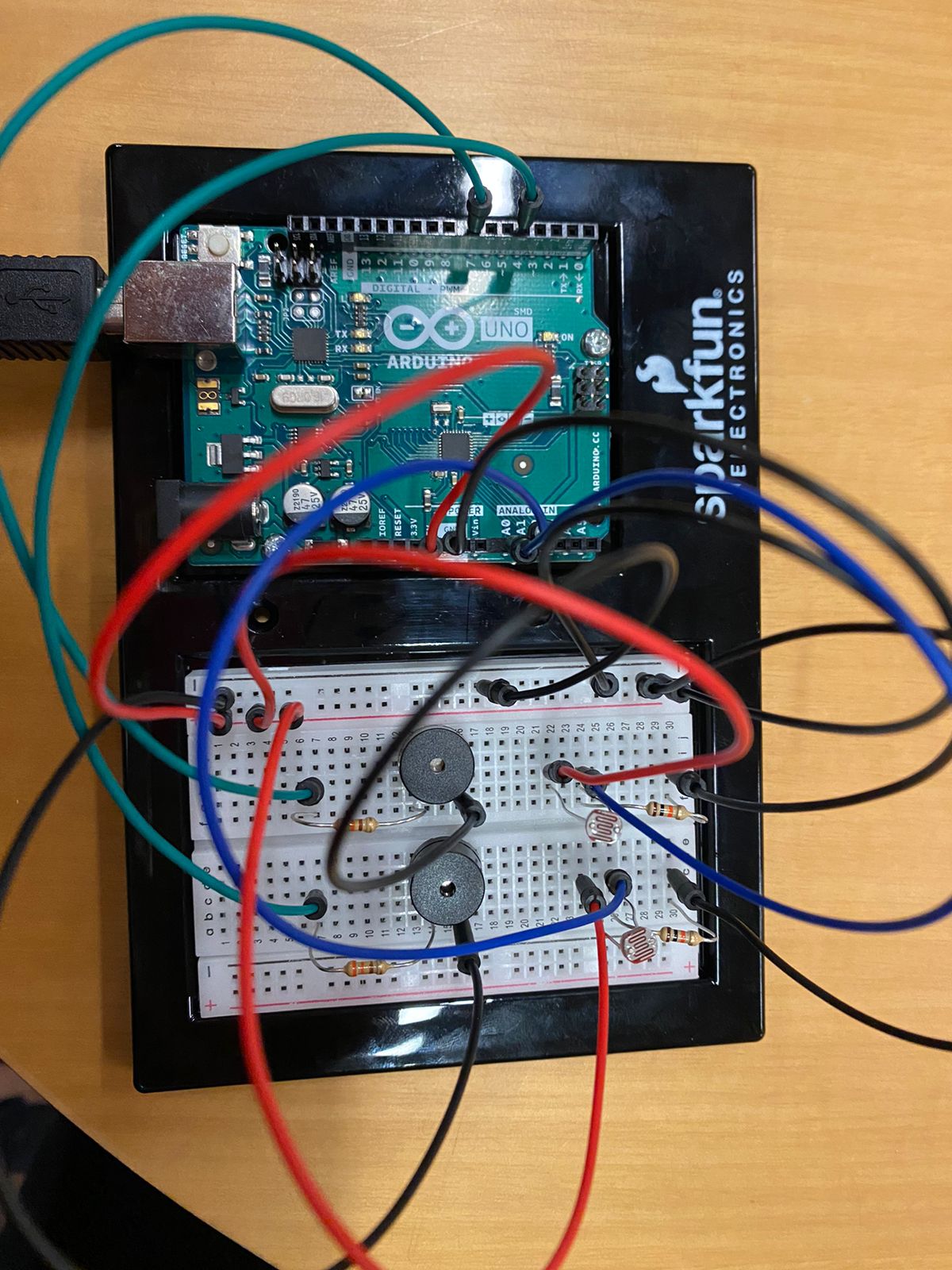
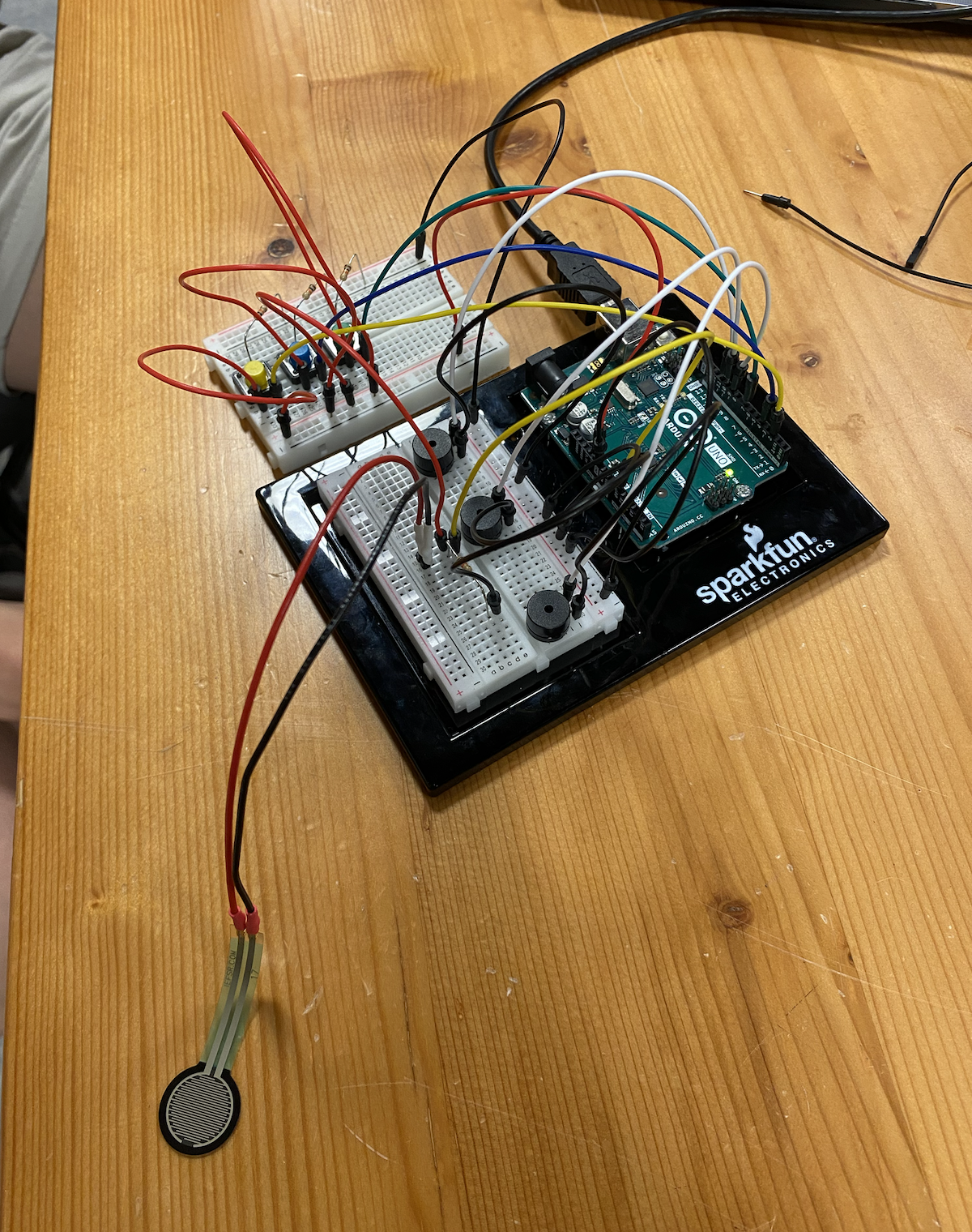 The circuit
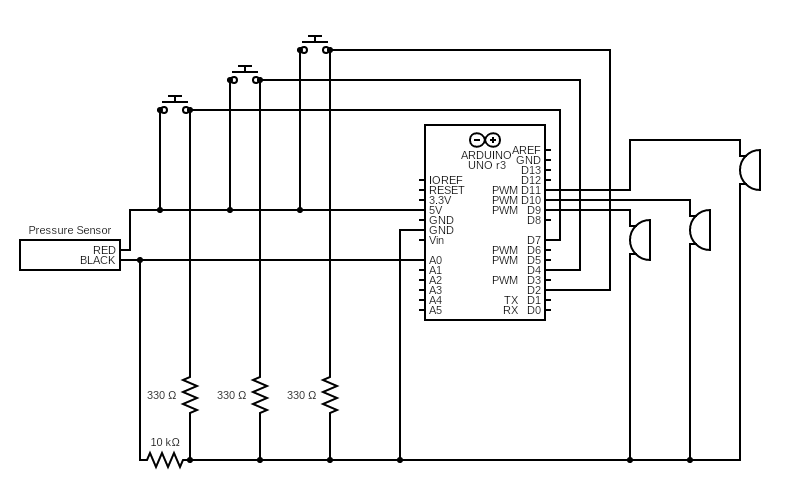 Circuit Diagram