Concept
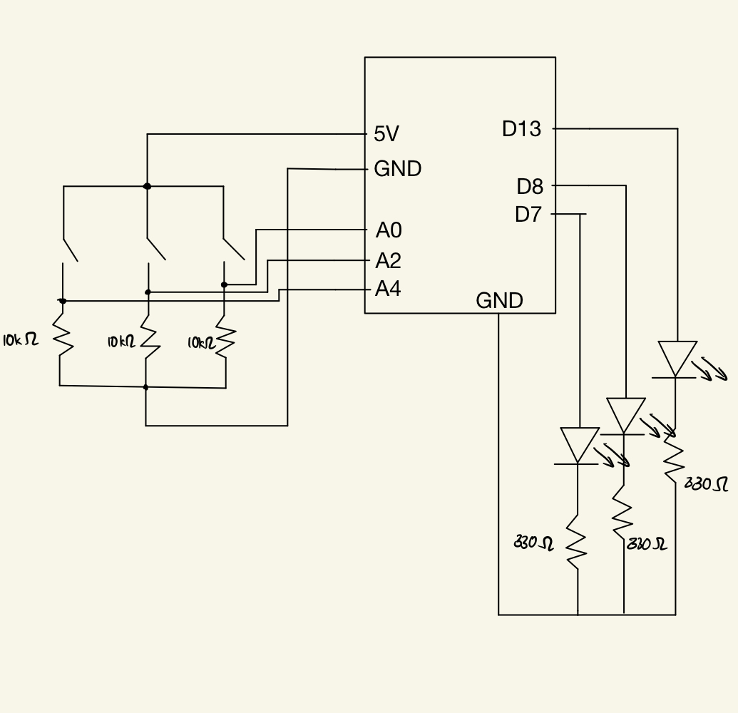
With this assignment, I wanted to implement a traffic light system. The system would light up the red, yellow, and green LED in order, and independently if needed. Below is a circuit diagram for the implementation of the traffic light:
Video
Implementation
There are three major features I included in this assignments:
- LED and Switch: I implemented the basic light switch, such that the LED lights up when their respective coloured switch is pressed.
- Two Switch: When you press two switches at once, their respective LEDs simulate a FizzBuzz pattern as such: Given a starting
index
- Both LEDs are turned off when
index is divisible by 15.
- Both LEDs are turned on when
index is divisible by 3 and 5.
- LEDs alternate to light up when
index is numbers other than ones mentioned above.
- Three Switch: When you press three switches at once, they simulate a traffic light, such that they oscillate from red -> yellow -> green and back for a couple of times.
Code:
const int red_in = A0;
const int yellow_in = A2;
const int green_in = A4;

const int red_out = 13;
const int yellow_out = 8;
const int green_out = 7;

const int NUM = 5;
int index;

void light_up(int out) {
  digitalWrite(out, HIGH);
  delay(500);
  digitalWrite(out, LOW);
}

void run_fizzbuzz(int out1, int out2) {
  // checking the state of the buttons, so that we do not run the code when the buttons are not pressed
  int red_switch = digitalRead(red_in);
  int yellow_switch = digitalRead(yellow_in);
  int green_switch = digitalRead(green_in);

  while (red_switch == HIGH || yellow_switch == HIGH || green_switch == HIGH) {
    // regular checking for the button press
    red_switch = digitalRead(red_in);
    yellow_switch = digitalRead(yellow_in);
    green_switch = digitalRead(green_in);

    if (index % 15 == 0) {
      digitalWrite(out1, LOW);
      digitalWrite(out2, LOW);
    } else if (index % 3 == 0 || index % 5 == 0) {
      digitalWrite(out1, HIGH);
      digitalWrite(out2, HIGH);
      delay(300);
      digitalWrite(out1, LOW);
      digitalWrite(out2, LOW);
    } else if (index % 2 != 0) {
      light_up(out1);
    } else if (index % 2 == 0) {
      light_up(out2);
    }

    delay(100);
    digitalWrite(out1, LOW);
    digitalWrite(out2, LOW);
    index++;

    if (index > 20)
      break;
  }
}

void setup() {
  // defining the digital output and digital input for the LEDs
  pinMode(red_in, INPUT);
  pinMode(yellow_in, INPUT);
  pinMode(green_in, INPUT);
  pinMode(red_out, OUTPUT);
  pinMode(yellow_out, OUTPUT);
  pinMode(green_out, OUTPUT);
}

void loop() {
  // Code base for the LEDs
  /*
    OBJECTIVE: Simulate Traffic Light
  */

  // reading the switch state
  int red_switch = digitalRead(red_in);
  int yellow_switch = digitalRead(yellow_in);
  int green_switch = digitalRead(green_in);

  // starting index for FizzBuzz
  index = 1;

  // if all of them are pressed, start simulating a traffic light: RED -> YELLOW -> GREEN. Oscillate between these every few seconds
  if (red_switch == HIGH && yellow_switch == HIGH && green_switch == HIGH) {
    // simulate the traffic light

    // this is a blocking function, as no inputs are registered as long at this loop is running.
    for (int i = 0; i < NUM; i++) {
      light_up(red_out);
      delay(100);
      light_up(yellow_out);
      delay(100);
      light_up(green_out);
      delay(100);
    }

  } else if (red_switch == HIGH && yellow_switch == HIGH && green_switch == LOW) {
    // if the red and yellow switch are turned on, run a FizzBuzz algorithm, such that every multiple of 3, 5 or 15 lights of both the LED, while the LEDs oscillate between each other during other iterations
    run_fizzbuzz(red_out, yellow_out);

  } else if (red_switch == HIGH && yellow_switch == LOW && green_switch == HIGH) {
    // if the red and yellow switch are turned on, run a FizzBuzz algorithm, such that every multiple of 3, 5 or 15 lights of both the LED, while the LEDs oscillate between each other during other iterations
    run_fizzbuzz(red_out, green_out);

  } else if (red_switch == LOW && yellow_switch == HIGH && green_switch == HIGH) {
    // if the red and yellow switch are turned on, run a FizzBuzz algorithm, such that every multiple of 3, 5 or 15 lights of both the LED, while the LEDs oscillate between each other during other iterations
    run_fizzbuzz(yellow_out, green_out);

  } else {
    // light up red when red switch is pressed
    if (red_switch == HIGH)
      digitalWrite(red_out, HIGH);

    // light up yellow when
    if (yellow_switch == HIGH)
      digitalWrite(yellow_out, HIGH);

    // light up gree when
    if (green_switch == HIGH)
      digitalWrite(green_out, HIGH);
  }

  // default state
  digitalWrite(red_out, LOW);
  digitalWrite(yellow_out, LOW);
  digitalWrite(green_out, LOW);
}
Improvement
There is probably a better way to implement the circuit, and the code. The Two Switch features only works when you keep on pressing the button, as opposed to pressing them once and letting the code run. However, this is intended such that pressing two buttons simultaneously by mistake does not lead to the user, waiting for the FizzBuzz to end. However, I have made the Three Switch feature, blocking, such that the user waits for the traffic light animation to end in order to provide other inputs again.