Week 9 – RGB Color Mixer and Potentiometer Intensity Scale

Concept

For this week’s assignment we were to utilize digital and analog read and write to control some LEDs. For the digital component, I built a circuit that utilizes three switches and an RGB LED to create a simple RGB color mixer. It was a pretty straightforward concept that utilized a component we had not talked about in detail during class.

Simple RGB Color Mixer

Implementation

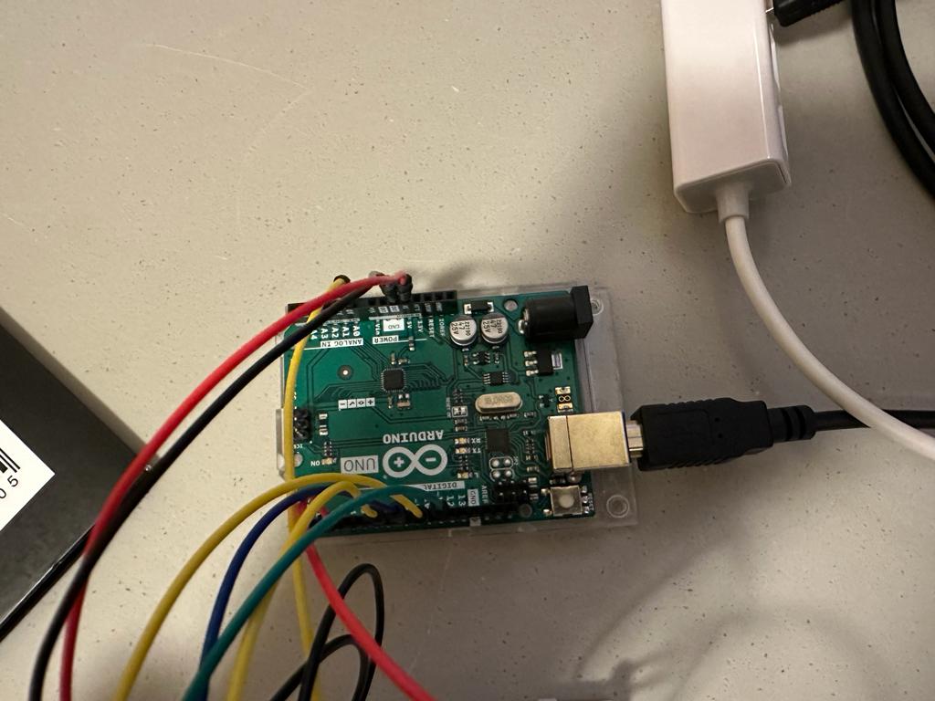
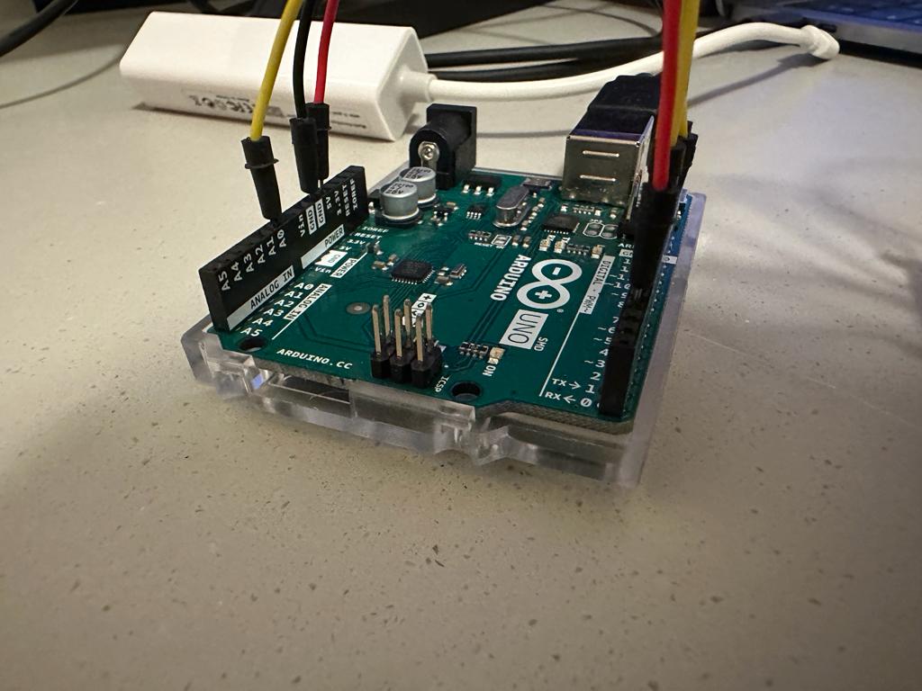
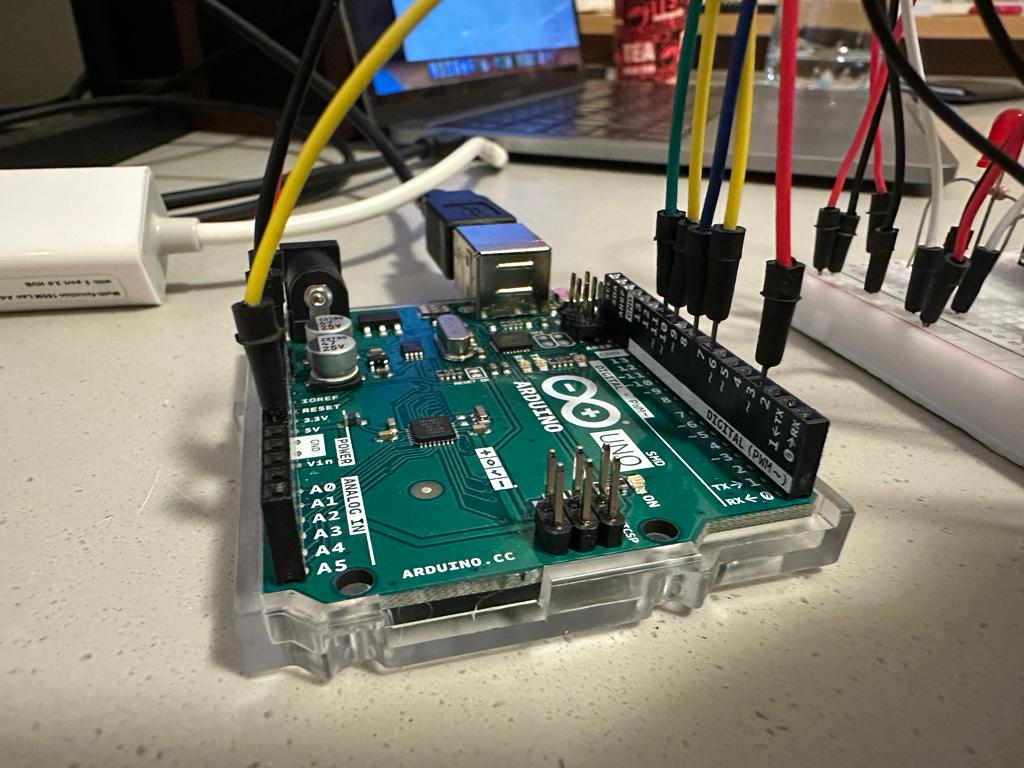
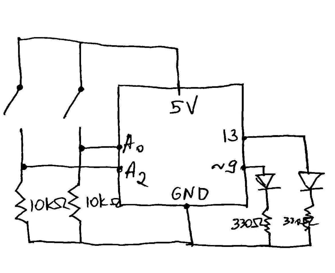
To implement this circuit I used an RGB LED, three switches, resistors and wires and an Arduino. The circuit was pretty simple and utilized some knowledge on parallel connections which can be seen in the diagram below:

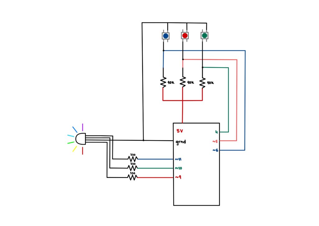
The RBG diode functions as a three-in-one diode and displays 7 colors (including white which I know might not be a color) when used for digital output. To run the switch, I wrote some code for the Arduino which can be bound below

// Diode output initialization
const int red_o = 9; 
const int green_o = 10;
const int blue_o = 11;

// Diode input initialization
const int red_i = 5; 
const int green_i = 4;
const int blue_i = 6;

// Diode counters initialization
int b_counter = 0;
int r_counter = 0;
int g_counter = 0;

void setup(){
  // Input pin modes for the diode inputs
  pinMode(red_i, INPUT);
  pinMode(blue_i, INPUT);
  pinMode(green_i, INPUT);

  // Output pin modes for the diode outputs
  pinMode(red_o, OUTPUT);
  pinMode(green_o, OUTPUT);
  pinMode(blue_o, OUTPUT);
  
  // Debugging
  Serial.begin(9600);
}


void loop(){
  // Button state initialization
  int redButtonState = digitalRead(red_i);
  int blueButtonState = digitalRead(blue_i);
  int greenButtonState = digitalRead(green_i);

  /* 
  Color mixing options:

  Red -> Red diode output
  Green -> Green diode output
  Blue -> Blue diode output

  Cyan -> Blue and green diode output
  Purple/Magenta -> Red and blue diode output
  Yellow -> Red and green diode output

  White -> All three diode output

  */
  
  if (blueButtonState == LOW) {
    b_counter++;
    delay(1000);
  }

  if (redButtonState == LOW) {
    r_counter++;
    delay(1000);
  }

  if (greenButtonState == LOW) {
    g_counter++;
    delay(1000);
    Serial.println(g_counter);
  }

  if (g_counter == 1 && b_counter == 1 && r_counter == 1) {
    digitalWrite(red_o, HIGH);
    digitalWrite(green_o, HIGH);
    digitalWrite(blue_o, HIGH);
  }
  else if (g_counter == 1 && b_counter == 1) {
    digitalWrite(red_o, LOW);
    digitalWrite(green_o, HIGH);
    digitalWrite(blue_o, HIGH);
  }

  else if (g_counter == 1 && r_counter == 1) {
    digitalWrite(red_o, HIGH);
    digitalWrite(green_o, HIGH);
    digitalWrite(blue_o, LOW);
  }

  else if (r_counter == 1 && b_counter == 1) {
    digitalWrite(red_o, HIGH);
    digitalWrite(green_o, LOW);
    digitalWrite(blue_o, HIGH);
  }
  
  else if (b_counter == 1) {
    digitalWrite(red_o, LOW);
    digitalWrite(green_o, LOW);
    digitalWrite(blue_o, HIGH);
  }
  
  else if (r_counter == 1) {
    digitalWrite(red_o, HIGH);
    digitalWrite(green_o, LOW);
    digitalWrite(blue_o, LOW);
  }
  
  else if (g_counter == 1) {
    digitalWrite(red_o, LOW);
    digitalWrite(green_o, HIGH);
    digitalWrite(blue_o, LOW);
  }

  else {
    digitalWrite(red_o, LOW);
    digitalWrite(green_o, LOW);
    digitalWrite(blue_o, LOW);
  }

  // Counters for diodes
  // Work on 1/0 basis
  if(b_counter >= 2){
    b_counter=0;
  }
  
  if(r_counter >= 2){
    r_counter=0;
  }

  if(g_counter >= 2){
    g_counter=0;
  }

  // Debugging
  // Serial.print(b_counter);
  // Serial.print(" ");
  // Serial.print(r_counter);
  // Serial.print(" ");
  // Serial.println(g_counter);
}

Challenges

In the beginning I hoped to join both the analog and digital components of the assignment, but after finishing the digital (RGB color mixer), I soon realized that I do not have enough power to put both on a breadboard as my computer was not allowing me to proceed onwards. The idea was to increase the intensity of the RGB colors, once selected through the switches by using a potentiometer. Unfortunately, since it did not work even though I tried adding more power to the circuit, I decided to recreate the concept on a separate breadboard.

Potentiometer Intensity Scale

Implementation

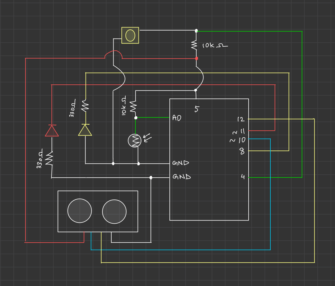
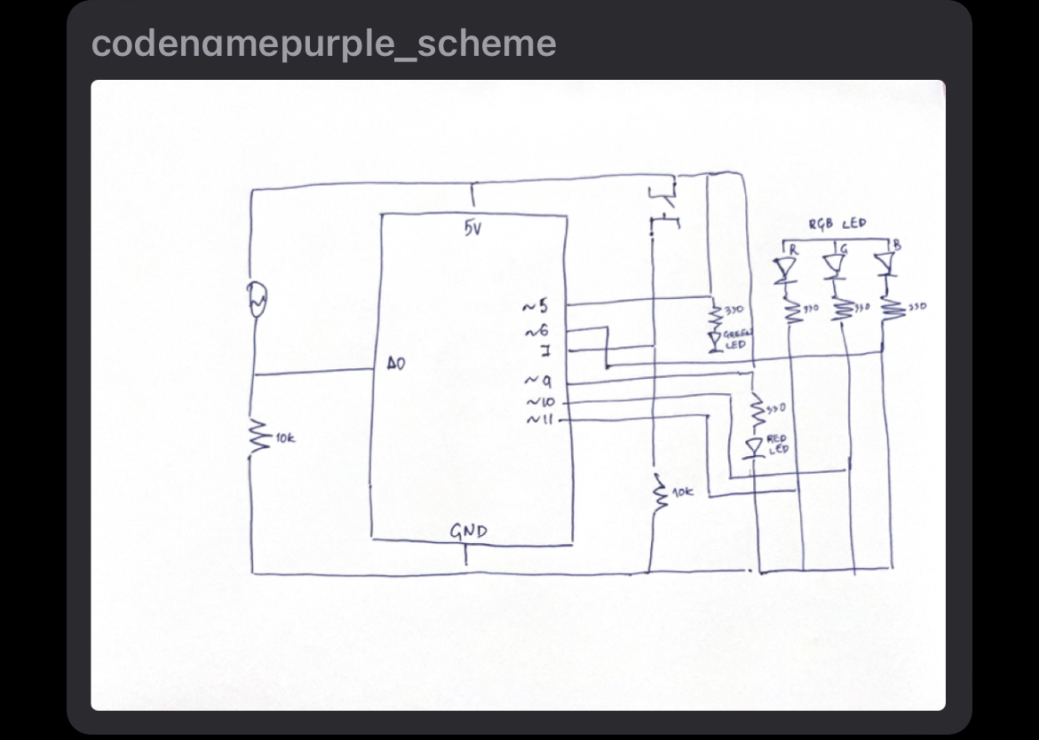
To implement this circuit, I used 6 LEDs, a potentiometer, resistors and wires, as well as an Arduino. The LEDs and the switch were connected in parallel to preserve the voltage across components. The LEDs and the switch were then connected to PWM outputs and analog input respectively. The diagram of the circuit is below:

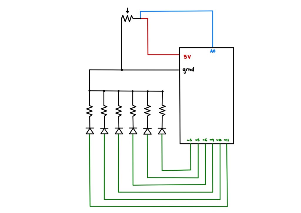
To run the circuit I wrote some Arduino code which utilized the mapping function in order to sequentially light up the diodes according to the potentiometer reading.

// Potentiometer input initialization
const int p_meter = A0;

// Diode output initialization
const int p_1 = 3;
const int p_2 = 5;
const int p_3 = 6;
const int p_4 = 9;
const int p_5 = 10;
const int p_6 = 11;


void setup() {
  // Potentiometer input
  pinMode(p_meter, INPUT);

  // Diode output
  pinMode(p_1, OUTPUT);
  pinMode(p_2, OUTPUT);
  pinMode(p_3, OUTPUT);
  pinMode(p_4, OUTPUT);
  pinMode(p_5, OUTPUT);
  pinMode(p_6, OUTPUT);

  // Debugging
  Serial.begin(9600);
}

void loop() {
  // Getting reading from potentiometer
  int potentiometer = analogRead(p_meter);

  // Mapping the reading to a value between 0 and 60
  // since there are 6 diodes
  // The interwal of each diode is hence 10
  int map_p = map(potentiometer, 0, 1023, 0, 60);
  
  // The logic is the same for each diode
  // If the value of the map is in a range of 10
  // respectful to the diode's range, then map the 
  // range of 10 to an increase in brightness of the diode
  if(map_p > 0 && map_p <= 10){
    int value1 = map(map_p, 0, 10, -10, 255);
    analogWrite(p_1, value1);
  }
  // Otherwise, turn off the diode
  else if(map_p == 0){
    analogWrite(p_1, 0);
  }
  if(map_p > 10 && map_p <= 20){
    int value2 = map(map_p, 10, 20, -10, 255);
    Serial.println(value2);

    analogWrite(p_2, value2);
  }
  else if(map_p < 10){
    analogWrite(p_2, 0);
  }
  if(map_p > 20 && map_p <= 30){
    int value3 = map(map_p, 20, 30, -10, 255);
    analogWrite(p_3, value3);
  }
  else if(map_p < 20){
    analogWrite(p_3, 0);
  }
  if(map_p > 30 && map_p <= 40){
    int value4 = map(map_p, 30, 40, -10, 255);
    analogWrite(p_4, value4);
  }
  else if(map_p < 30){
    analogWrite(p_4, 0);
  }
  if(map_p > 40 && map_p <= 50){
    int value5 = map(map_p, 40, 50, -10, 255);
    analogWrite(p_5, value5);
  }
  else if(map_p < 40){
    analogWrite(p_5, 0);
  }
  if(map_p > 50 && map_p <= 60){
    int value6 = map(map_p, 50, 60, -10, 255);
    analogWrite(p_6, value6);
  }
  else if(map_p < 50){
    analogWrite(p_6, 0);
  }
}

Challenges

As stated above, I was displeased that the intensity factor was not visible within one circuit. For this circuit, the hardest part was the mapping of the values such that the code runs properly. It took some time to realize that some of the diodes were broken and were not lighting up. Since I worked a diode at a time, the fact that one would just not light up was very frustrating. It is important to check diodes before starting, which is something I will do from now on.

Reflection

This assignment was very interesting to me. Since I never worked individually on a circuit that involves code, deducing how the Arduino works in accordance to the circuit I built was a very enriching experience. The frustration over faulty components is inevitable while working with electronics but it goes to show that code is not the only thing that might mess up the end product. In the future, I wish to be able to work on a larger breadboard with a larger power input so that my laptop would not prevent me from adding as many components as I want.

Traffic Control with Photosensor.


Concept.

The concept for this project is pretty simple. How can traffic be regulated in a smart, optimized way such that when there are more cars and fewer pedestrians, the traffic light stays green for longer? In an advanced way, could we have sensors that could calculate traffic and find an optimized way to control them? That was how I came up with this project. The photoresist represents traffic: the light turns green when more cars are stuck in traffic. Pedestrians, on the other hand, can utilize the switch to inform the system of their intention to cross. When the switch is turned on, the traffic turns red.


Process.

The project features two LEDs, a photoresist to check the number of traffic, a switch, jumper wires, and four 10K ohms resistors. The photoresistor keeps track of the amount of traffic (the higher the traffic), the higher the resistance, which results in the traffic light turning green.

Challenges

One of the challenges I was faced with was designing a code that would ensure one of the lights stayed on until a condition was met. It took me a while to figure out that the “switch” statement in javascript would be the most convenient way forward. That aside, figuring out how to connect the photoresistor after appropriately connecting the LEDs and the switch proved difficult. I got to a point where I assumed the photoresistor was faulty. However, it started working after I dismantled everything and reconnected the circuit differently.

Overall, this project challenged me to think more creatively, and it also helped me gain a better understanding of coming up with appropriate Arduino circuits.


Week 9 – Switches and LEDs

Concepts and methods

For this assignment, I wanted to simulate police lights so I used two LEDs (blue and red) and two push (button switches). Each switch turns on the respectively colored LED, and when both switches are pressed the LEDs blink continuously looking like police lights.

Schematic

Code

//Declare the button switches and the LEDs 
const int BUTTON1 = 2;
const int BUTTON2 = 5;
const int LED1 = 8;
const int LED2 = 12;
int BUTTONstate1 = 0;
int BUTTONstate2 = 0;

void setup()
{
//Declare the buttons as input and the LEDs as output
pinMode(BUTTON1, INPUT);
pinMode(BUTTON2, INPUT);
pinMode(LED1, OUTPUT);
pinMode(LED2, OUTPUT);
}

void loop()
{
// Turn on the blue LED by pressing the blue switch
BUTTONstate1 = digitalRead(BUTTON1);
if (BUTTONstate1 == HIGH)
{
digitalWrite(LED1, HIGH);
}
else{
digitalWrite(LED1, LOW);
}
//Turn on the Red LED by pressing the red switch
BUTTONstate2 = digitalRead(BUTTON2);
if (BUTTONstate2 == HIGH)
{
digitalWrite(LED2, HIGH);
}
else
{
digitalWrite(LED2, LOW);
}
//Blink the two LEDs when the two switches are pressed
if (BUTTONstate1 == HIGH && BUTTONstate2 == HIGH){
digitalWrite (LED1, HIGH);   
digitalWrite (LED2, LOW);   
delay(750);  // Wait 750ms  
digitalWrite (LED1, LOW);  
digitalWrite (LED2, HIGH);  
delay(500);  // Wait 500ms 
}
}

Video

Future Improvements 

In the future, I would like to experiment with a greater number of LEDs. Additionally, I would like to implement analog switches such as the potentiometer next.

Week 9 – Ghost Detector

Concept

For this project, I decided to detect ghosts (or any other presence) using an ultrasonic sensor and a red “SOS” LED, and transmit a message saying “hi” using Morse code on a yellow LED. I looked up the Morse codes from this website. The circuit diagram for my ghost detector can be found below:

Implementation

I used 2 sensors for this project: an LDR and an ultrasonic sensor.
The LDR detects if the surroundings are dark enough and the ultrasonic sensor detects if there is “something” nearby 🙂

If the ultrasonic sensor detects something is near, and if the surroundings are dark, the red LED blinks an SOS signal in Morse code. While the red LED is flashing, you know something is nearby, that’s where the yellow switch comes in. When we press the yellow switch, the yellow LED starts blinking “hi” in Morse code to give a friendly message to whatever was detected by the ultrasonic sensor. While the yellow LED is flashing, the red LED doesn’t flash an SOS signal because we wish to portray a positive vibe to our new friend.

The digital part of the circuit consists of the switch that reads digital signals and turns the yellow LED on and the red LED off. The ultrasonic sensor feeds in pulse data through its ECHO pin, which is then converted into a float distance value using a simple equation. The analog part consists of an LDR which is used to detect whether it is dark enough for the red SOS to start blinking. I did an analog read to get lighting info from this sensor and used it inside the if condition for the red LED.

To implement the “SOS” and “hi” signals in the two LEDs, I made use of two functions. I utilized the idea we discussed in class where we made an LED blink. I used a simple for loop to make the LED blink the required number of times and adjusted the delays between blinks to make the LED blink fast or slow. This allowed me to depict any letter in the Morse code using my LEDs. Once this was done, I caught the readings from the sensors and the switch to make the LEDs blink accordingly.

The code for my project can be found below:

int pushButton = 4;    // for the push button switch
int red_ledPin = 11;   // Define the red LED pin number
int yellow_ledPin = 8; // Define the yellow LED pin number

const int TRIG_PIN = 10;           // Arduino pin connected to Ultrasonic Sensor's TRIG pin
const int ECHO_PIN = 12;           // Arduino pin connected to Ultrasonic Sensor's ECHO pin
const int DISTANCE_THRESHOLD = 50; // in centimeters

// distance calculation variables for ultrasonic sensor:
float duration_us, distance_cm;

// the setup routine runs once when you press reset:
void setup()
{
    pinMode(red_ledPin, OUTPUT);    // set the red LED to output mode
    pinMode(yellow_ledPin, OUTPUT); // set the yellow LED to output mode
    pinMode(TRIG_PIN, OUTPUT);      // set arduino pin to output mode
    pinMode(ECHO_PIN, INPUT);       // set arduino pin to input mode

    // initialize serial communication at 9600 bits per second:
    Serial.begin(9600);
    // make the pushbutton's pin an input:
    pinMode(pushButton, INPUT);
}

// the loop routine runs over and over again forever:
void loop()
{
    // send a 10us pulse to the ultrasonic sensor
    digitalWrite(TRIG_PIN, HIGH);
    delayMicroseconds(10);
    digitalWrite(TRIG_PIN, LOW);

    // measure duration of pulse from ECHO pin
    duration_us = pulseIn(ECHO_PIN, HIGH);
    // calculate the distance
    distance_cm = 0.017 * duration_us;

    // read the input pin:
    int buttonState = digitalRead(pushButton);
    int sensorValue = analogRead(A0);

    // if the button is not pressed, the distance is closer than 15cm, and it is dark enough, then blink SOS
    if (buttonState == HIGH && distance_cm < 15 && sensorValue > 800)
    {
        blinkSOS(red_ledPin);
    }
    // otherwise if the button is pressed, then blink "hi" on the yellow LED
    else if (buttonState == LOW)
    {
        digitalWrite(red_ledPin, LOW);
        blinkHi(yellow_ledPin);
    }

    // for debugging: 

    // // print out the state of the button:
    // Serial.println(buttonState);
    // delay(1); 

    // // print the value to Serial Monitor
    // Serial.print("distance: ");
    // Serial.print(distance_cm);
    // Serial.println(" cm");

    // delay(10);

    // Serial.println(sensorValue);
    // delay(1);
}

// Morse code for "SOS": ... --- ...
void blinkSOS(int ledNum)
{
    // fast blink thrice for "..."
    for (int i = 0; i < 3; i++)
    {
        digitalWrite(ledNum, HIGH); // turn the LED on (HIGH is the voltage level)
        delay(150);                 // wait for a second
        digitalWrite(ledNum, LOW);  // turn the LED off by making the voltage LOW
        delay(150);                 // wait for a second
    }
    // wait between pattern switch
    delay(500);
    // slow blink for "---"
    for (int i = 0; i < 3; i++)
    {
        digitalWrite(ledNum, HIGH); // turn the LED on (HIGH is the voltage level)
        delay(400);                 // wait for a second
        digitalWrite(ledNum, LOW);  // turn the LED off by making the voltage LOW
        delay(400);                 // wait for a second
    }
    // wait between pattern switch
    delay(500);
}

// Morse code for "hi": .... ..
void blinkHi(int ledNum)
{
    // blink 4 times for "...."
    for (int i = 0; i < 4; i++)
    {
        digitalWrite(ledNum, HIGH); // turn the LED on (HIGH is the voltage level)
        delay(150);                 // wait for a second
        digitalWrite(ledNum, LOW);  // turn the LED off by making the voltage LOW
        delay(150);                 // wait for a second
    }
    // wait between pattern switch
    delay(500);
    // blink twice for ".."
    for (int i = 0; i < 2; i++)
    {
        digitalWrite(ledNum, HIGH); // turn the LED on (HIGH is the voltage level)
        delay(150);                 // wait for a second
        digitalWrite(ledNum, LOW);  // turn the LED off by making the voltage LOW
        delay(150);                 // wait for a second
    }
    // wait between pattern switch
    delay(500);
}

Challenges

I spent a lot of time on this project playing around with wires and experimenting, especially when I was running into unusual results. The difficult part though, was that in order to test a simpler, shorter circuit to clear my confusion, I had to take apart the larger circuit I was working on since we only have one breadboard. At times I realized I was making a very small error which was almost impossible to notice in the larger circuit which had a ton of wires all over the board. Drawing the circuit diagram before implementing the physical circuit was helpful but at times I was confused as to which end a resistor would go to or if it would even make a difference. Whenever I was stuck somewhere, I tried looking at circuit diagrams for simpler, smaller circuits. For example, when I was stuck at implementing the yellow switch and was tired of trying out different connections to make it work, I looked up a simple basic circuit for a switch with an LED and tried to implement that into my larger circuit, and this proved very helpful.

The Ghost Detector


Sensors | Car Headlights

Concept

In this assignment, I implemented a circuit with an LDR sensor and a switch that were both used to replicate some basic functionality of car headlights.

I built an Arduino circuit that used an analog sensor and a digital sensor to control two LEDs – ‘car headlights’. Using a switch, I made two LEDs blink periodically as long as the switch is still pressed. By default state when the switch is released, two LEDs will have the brightness controlled by an LDR sensor. So, the idea was to reduce brightness when the LDR reading is high and increase it if it is low.

Demo

Code

If the switch is pressed, then 2 LEDs are blinking with some delay. If not, then the code uses the LDR value to set the brightness of LEDs to the appropriate value.

const int switchPin = 3; // the pin that the switch is connected to
const int ledPin1 = 6;   // the pin that the first LED is connected to
const int ledPin2 = 9;  // the pin that the second LED is connected to
const int ldrPin = A0;   // the pin that the LDR sensor is connected to

int switchState = 0;     // variable for reading the switch status
int ldrValue = 0;        // variable for storing the LDR sensor reading
int ledBrightness1 = 0;  // variable for storing the brightness of the first LED
int ledBrightness2 = 0;  

void setup() {
  pinMode(switchPin, INPUT);
  pinMode(ledPin1, OUTPUT);
  pinMode(ledPin2, OUTPUT);
  Serial.begin(9600);
}

void loop() {
  // read the switch state
  switchState = digitalRead(switchPin);

  // blink the LEDs if the switch is pressed
  if (switchState == LOW) {
    digitalWrite(ledPin1, LOW);
    digitalWrite(ledPin2, LOW);
    delay(500);
    digitalWrite(ledPin1, HIGH);
    digitalWrite(ledPin2, HIGH);
    delay(500);
  } else {
    // read the LDR sensor value
    ldrValue = analogRead(ldrPin);

    // map the LDR sensor value to the LED brightness range (0-255)
    ledBrightness1 = map(ldrValue, 0, 1023, 255, 0);
    ledBrightness2 = map(ldrValue, 0, 1023, 255, 0);

    // adjust the LED brightness
    analogWrite(ledPin1, ledBrightness1);
    analogWrite(ledPin2, ledBrightness2);
  }

  // print the LDR sensor value to the Serial Monitor
  Serial.println(ldrValue);

  delay(100);
}

Future changes

I feel that there is a lot of room for improvement in setting the brightness using an LDR sensor. The LEDs actually keep being bright with high LDR values, and it is a bit hard to get LDR values to the low level. Yet, the LDR sensor does make them brighter when the LDR readings become low eventually.

Assignment 6: Speed-o-Meter! (Analog Input/Output)

Concept

Driving in Abu Dhabi is pretty smooth with the traffic conditions, however, the constant fear of speeding fines keeps me on my toes whenever I am out on the UAE roads. This is what exactly I thought of exploring, as soon as I found out about the presence of an Ultrasonic Sensor in our Introduction to Interactive Media kits. If it can measure distance, we can measure the time between the change in distance and it will give us speed. This speed can indicate us whether we are going too fast, borderline fast, or in the normal range.

Being inspired from this, I decided to use the newly learnt Adruino and Circuit building skills to explore this complex possibility, which seemed very simple in theory!

Overview

To give a very brief overview, the goal of this project was to use an analog and a digital to sensor the control at least two LEDs, creating various effects that can be programmed. The LDR is used as an analog sensor to control the brightness of all LEDs, while an Ultrasonic Sensor is used to calculate the speed of moving objects, which then appropriately triggers an LED – depending on the speed of the object.

Project Demonstration

Here is a brief video that shows the Speed-o-Meter in action!

As a guide, when the speed is in a decently slow range, the Green light gets switched on. As we increase it, the Yellow Light gets switched on, and when we are moving too fast, the Red Light gets switched on. The colors of these lights can intuitively indicate their intended meaning, however the exact value of speed, while not necessary to know, is beyond 40cm/s for Yellow and beyond 90 cm/s for Red.

Moreover, something that is difficult to demonstrate with the camera, is the usage of the LDR. The analog values, read in the range of 0 to 1023, from the Light Sensor, are mapped between 255 to 0, inversely! The reason for this is for a brighter light to be displayed when there is light because it is difficult to see a dim bulb during the day. This is particularly difficult to demonstrate in my circuit because of the momentarily opening nature of the lights with the speed.

Circuit Pictures

How it Works

While I have touched upon it previously, the logic was slightly complex to implement. To explain in simple terms, our Ultrasonic Sensor sends a signal and then waits for it to bounce back and then return – measuring the distance of a round trip from an object. Now let’s say, the object was moved very quickly. We send another signal, in the span of a very minute time, and then measure the distance again. This will allow us to calculate the distance that was changed, over time. Essentially, this gives us the distance travelled by an object, over a specific time. While this is not perfect, it is definitely an interesting way to calculate the speed of an object, and satisfies our use case.

This logic can be demonstrated with the following piece of code:

// Sends a Signal and waits for it to be received back by the Ultrasonic Sensor
digitalWrite(trigPin, LOW);  // Set trig pin low
delayMicroseconds(2);        // Wait for 2 microseconds
digitalWrite(trigPin, HIGH); // Set trig pin high
delayMicroseconds(10);       // Wait for 10 microseconds
digitalWrite(trigPin, LOW);  // Set trig pin low

float duration = pulseIn(echoPin, HIGH); // Measure the duration of the echo pulse
float distance = duration * 0.034 / 2;   // Calculate the distance in centimeters

float speed = 0.0;
if (distance > 0.0) {
  // Stores the Previous Distance 
  prevDistance = distance;
  delay(500); // Wait for 500 milliseconds to measure the distance again

  // Then goes for measuring the distance again!
  digitalWrite(trigPin, LOW);  // Set trig pin low
  delayMicroseconds(2);        // Wait for 2 microseconds
  digitalWrite(trigPin, HIGH); // Set trig pin high
  delayMicroseconds(10);       // Wait for 10 microseconds
  digitalWrite(trigPin, LOW);  // Set trig pin low
  duration = pulseIn(echoPin, HIGH); // Measure the duration of the echo pulse again
  distance = duration * 0.034 / 2;   // Calculate the distance in centimeters again

  // Just for debugging
  Serial.print("Previous Distance: ");
  Serial.print(prevDistance);
  Serial.print(".  New Distance:  ");
  Serial.println(distance);

  // Then measures the change in distance, over time. 
  speed = (prevDistance - distance) / 0.1; // Calculate the speed in centimeters per second

Following this, once we have the speed, I used somewhat of a State Machine to trigger the different LEDs depending on the speed. I reached the optimum speed values in the condition through trial and error, and not by some particular calculation in mind:

  Serial.print("Object Moving at Speed: ");
  Serial.print(speed);
  Serial.println(" cm/s");

if((abs(speed)<40) && abs(speed)>=5){
  analogWrite(PIN_GREEN, brightness);
  analogWrite(PIN_YELLOW, 0);
  analogWrite(PIN_RED, 0);
}
else if (abs(speed)>=40 && abs(speed)<90){
  analogWrite(PIN_YELLOW, brightness);
  analogWrite(PIN_GREEN, 0);
  analogWrite(PIN_RED, 0);
}
else if (abs(speed)>=90){
  analogWrite(PIN_RED, brightness);
  analogWrite(PIN_YELLOW, 0);
  analogWrite(PIN_GREEN, 0);
}
else{
  analogWrite(PIN_YELLOW, 0);
  analogWrite(PIN_GREEN, 0);
  analogWrite(PIN_RED, 0);
}

The LDR is incorporated by obtaining the Analog Value, and mapping it to the range of possible brightness.  This brightness is then stored in a variable and has been used appropriately to trigger our LEDs (as seen in the above code).

ldrValue = analogRead(LDR_PIN); // read the input on analog pin
brightness = map(ldrValue, 0,1023, 0, 255);
Serial.print("Brightness: ");
Serial.println(brightness);

Difficulties

Being new to circuits, this was definitely a struggle. While the flow seems simple, if I look at it now, but the process threw multiple problems at me to cater to. The one to start off is the impossible measuring of the Distance, or more like the change in distance, from the Ultrasonic Sensor. This was because I had not added a delay, and spending some time and thinking through, alongside some trial and error helped with that.

Moreover, one particular challenge, which was a dumb mistake from my end, was using the pins 13,12, and 2 for the Green, Yellow, and Red LEDs. The issue with this was nothing other than not being able to vary the brightness in correspondence with the LDR values. It was only going through online resources, and reading the notes taken in class, which helped me figure out that I should instead use pins that have (like 11~, 10~, and 3~) if I want to vary the brightness.

Full Code

Though I have explained sections of code above, I am adding the entire code to this documentation since, unlike p5JS, we do not have a link to it. I’m sure this will give a good overview of how everything was put together!

const int trigPin = 8;  // Trig pin of the ultrasonic sensor
const int echoPin = 7; // Echo pin of the ultrasonic sensor
const int PIN_GREEN = 11; //Green LED connected on pin 13
const int PIN_YELLOW = 10; //Yellow LED connected on pin 12
const int PIN_RED = 3; //Yellow LED connected on pin 12
const int LDR_PIN = A0;
float prevDistance;
int ldrValue;
int brightness = 255;;

void setup() {
  Serial.begin(9600);   // Initialize serial communication
  pinMode(trigPin, OUTPUT); // Set trig pin as output
  pinMode(echoPin, INPUT);  // Set echo pin as input
  pinMode(PIN_GREEN, OUTPUT);
  pinMode(PIN_YELLOW, OUTPUT);
  pinMode(PIN_RED, OUTPUT);
}

void loop() {
  // Gets the Analog Value from the LDR Sensor
  ldrValue = analogRead(LDR_PIN); // read the input on analog pin
  brightness = map(ldrValue, 0,1023, 0, 255);
  Serial.print("Brightness: ");
  Serial.println(brightness);

  // Sends a Signal and waits for it to be received back by the Ultrasonic Sensor
  digitalWrite(trigPin, LOW);  // Set trig pin low
  delayMicroseconds(2);        // Wait for 2 microseconds
  digitalWrite(trigPin, HIGH); // Set trig pin high
  delayMicroseconds(10);       // Wait for 10 microseconds
  digitalWrite(trigPin, LOW);  // Set trig pin low
  
  float duration = pulseIn(echoPin, HIGH); // Measure the duration of the echo pulse
  float distance = duration * 0.034 / 2;   // Calculate the distance in centimeters
  
  float speed = 0.0;
  if (distance > 0.0) {
    // Stores the Previous Distance 
    prevDistance = distance;
    delay(500); // Wait for 100 milliseconds to measure the distance again

    // Then goes for measuring the distance again!
    digitalWrite(trigPin, LOW);  // Set trig pin low
    delayMicroseconds(2);        // Wait for 2 microseconds
    digitalWrite(trigPin, HIGH); // Set trig pin high
    delayMicroseconds(10);       // Wait for 10 microseconds
    digitalWrite(trigPin, LOW);  // Set trig pin low
    duration = pulseIn(echoPin, HIGH); // Measure the duration of the echo pulse again
    distance = duration * 0.034 / 2;   // Calculate the distance in centimeters again

    // Just for debugging
    Serial.print("Previous Distance: ");
    Serial.print(prevDistance);
    Serial.print(".  New Distance:  ");
    Serial.println(distance);

    // Then measures the change in distance, over time. 
    speed = (prevDistance - distance) / 0.1; // Calculate the speed in centimeters per second
  }

    Serial.print("Object Moving at Speed: ");
    Serial.print(speed);
    Serial.println(" cm/s");
  
  if((abs(speed)<40) && abs(speed)>=5){
    analogWrite(PIN_GREEN, brightness);
    analogWrite(PIN_YELLOW, 0);
    analogWrite(PIN_RED, 0);
  }
  else if (abs(speed)>=40 && abs(speed)<90){
    analogWrite(PIN_YELLOW, brightness);
    analogWrite(PIN_GREEN, 0);
    analogWrite(PIN_RED, 0);
  }
  else if (abs(speed)>=90){
    analogWrite(PIN_RED, brightness);
    analogWrite(PIN_YELLOW, 0);
    analogWrite(PIN_GREEN, 0);
  }
  else{
    analogWrite(PIN_YELLOW, 0);
    analogWrite(PIN_GREEN, 0);
    analogWrite(PIN_RED, 0);
  }

  prevDistance = 0;
  speed=0;
  distance = 0;
  
  delay(500); // Wait for 500 milliseconds before measuring again
}


Analog Input/Output

Idea

While I really like sunlight or natural light filtering in through my window, if I am deeply focused on a task I often forget to turn the lights on when the sun has set and this has often lead to headaches and dryness in my eyes due to eye strain when working on my laptop in the dark. So I wanted to create an indicator using a light sensor and LED in which the LED starts to blink if the light in the room is very dim. The glaring red alarm LED can only be temporarily switched to a blue light when a button is pressed down because I often get lazy and don’t get up to turn on the lights. So the red light would continue to blink as long as lights are not turned on and it becomes brighter in the room.

Circuit

I created the following circuit for the light indicator. I connected the LDR with a pull down resistor of 10K Ω and in the same circuit added the red LED with its respective resistor of 330Ω. Then I connected the red LED and LDR with the blue LED through a button and following is the Arduino Uno code for the circuit:

const int BUTTON = 7; // the number of the pushbutton pin on the arduino board
int lastState = LOW; // the last state from the button
int currentState;    // the current reading from the button
const int LIGHT_SENSOR_PIN = A0; 
const int LED_PIN          = 3;  
const int LED_PIN_2          = 11;  
const int ANALOG_THRESHOLD = 500;
int Analog;

void setup() {
  Serial.begin(9600);
  pinMode(LED_PIN, OUTPUT); 

  pinMode(BUTTON, INPUT_PULLUP);
}

void loop() {
  Analog = analogRead(LIGHT_SENSOR_PIN); // read the input on LDR

  currentState = digitalRead(BUTTON); //read input on button 
  if(Analog < ANALOG_THRESHOLD){
    if (currentState==HIGH){
      digitalWrite(LED_PIN, HIGH);   // turn LED on 
      delay(500);                       // wait 
      digitalWrite(LED_PIN, LOW);    // turn LED off 
      delay(500);
    }
    else{
      digitalWrite(LED_PIN_2, HIGH);   // turn LED 
      delay(500);                       // wait 
      digitalWrite(LED_PIN_2, LOW);    // turn LED off 
      delay(500);
    }    
  
  }
  else{
    digitalWrite(LED_PIN, LOW);  // turn LED off
  }


}


Improvements

For future improvements I would want to add some sort of sound alarm to it as well so that I do not ignore the indicator at all because of the noise. I would also like to add a LED that starts blinking again after a set time period of the lights are not turned on in for example 5 minutes or something similar to this.

Week 9 – Yerkebulan Imanbayev

Concept:

For my digital sensors assignment, I used the sun and the moon as an inspiration. I used a yellow LED to represent the sun and a blue LED to represent the moon.

Implementation:

When the yellow button is pressed, the yellow LED – a.k.a. the Sun – lights up and when the blue button is pressed, the blue LED – a.k.a. the moon – lights up. When both buttons are pressed at the same time, they each blink and alternate for 1 second with an interval of 0.5 seconds, representing the cycle of the sun and the moon.

Circuit schematics: 

Video:

Code:

int yellowLED = 13; //labeling the digital output for the yellow LED
int blueLED = 9; //labeling the digital output for the blue LED

void setup() {
  pinMode(yellowLED, OUTPUT);
  pinMode(blueLED, OUTPUT);
  pinMode(A0, INPUT);
  pinMode(A2, INPUT);
}

void loop(){

  int switchPositionYellow = digitalRead(A0);
  int switchPositionBlue = digitalRead(A2);

  if (switchPositionYellow == HIGH) { //if the yellow button is pressed, the yellow LED is turned on
    digitalWrite(yellowLED, HIGH);
    digitalWrite(blueLED, LOW);
  }

  else if (switchPositionBlue == HIGH) { // if the blue button is pressed, the blue LED is turned on
    digitalWrite(yellowLED, LOW);
    digitalWrite(blueLED, HIGH);
  }

  else {
    digitalWrite(yellowLED, LOW); //if both buttons aren't pressed, the LEDs are turned off
    digitalWrite(blueLED, LOW);
  }

  if (switchPositionYellow == HIGH && switchPositionBlue == HIGH) { //if both buttons are pressed, 
                                                                    //both LEDS will blink and will alternate
    digitalWrite(yellowLED, HIGH); 
    delay(1000);                      
    digitalWrite(yellowLED, LOW);   
    delay(500);       

    digitalWrite(blueLED, HIGH);  
    delay(1000);                      
    digitalWrite(blueLED, LOW);   
    delay(500);       
  }
}

Future Improvements:

In the future, I want to uphold and develop the concept Moresby including an analog sensor that detects light. When the light shines, “the sun” – yellow LED – would turn on, and when the light does not shine, “the moon” – blue LED – would turn on.

HW6: Analog and Digital, Input & Output – “code name: Purple”

CONCEPT

For this assignment, I have made a game called “code name: Purple”. The player is presented with an RGB LED that changes color based on the reading from a photosensor. The goal of the game is to press a button when the RGB LED turns the right shade of purple, which may be not discernable to the eye, so the only way for the player to find out is to play around with the photosensor and check by pressing the button. If the button is pressed at the right photoresistor value, a green LED lights up, indicating that the player has won. If the button is pressed at the wrong photoresistor value, a red LED lights up, indicating that the player has lost.

IMPLEMENTATION

I faced several challenges while setting up the circuit. Initially, I had difficulty understanding the pin mapping for the RGB LED and the photosensor. I had to refer to the documentation and online resources to understand how to wire these components to the Arduino. After some trial and error, I was able to successfully wire the components and read the analog values from the photosensor.

Another challenge was in getting the timing of the button press just right. Initially, I had set a fixed delay between the LED turning purple and the button press is registered. However, this did not work well as the timing varied depending on the ambient light level. I had to modify my code to dynamically adjust the timing of the button press based on the current color value of the LED. After some experimentation and tweaking, I was able to get the timing of the button press just right, and the game was fully functional.

schematic used

Below is the full code.

// define pins
int redLED = 9;
int greenLED = 5;
int rgbRed = 11;
int rgbGreen = 10;
int rgbBlue = 6;
int btnPin = 7;
int photoPin = A0;

// variables
int redVal = 0;
int greenVal = 0;
int blueVal = 0;
int photoVal = 0;
int btnState = 0;

void setup() {
  // set pins
  pinMode(redLED, OUTPUT);
  pinMode(greenLED, OUTPUT);
  pinMode(rgbRed, OUTPUT);
  pinMode(rgbGreen, OUTPUT);
  pinMode(rgbBlue, OUTPUT);
  pinMode(btnPin, INPUT);

  // initialize serial communication
  Serial.begin(9600);
}

void loop() {
  // read the photoresistor value
  photoVal = analogRead(photoPin);

  // map the photoresistor value to RGB LED color values
  redVal = map(photoVal, 0, 1023, 0, 255);
  greenVal = 0;
  blueVal = map(photoVal, 0, 1023, 255, 0);

  // set RGB LED color
  analogWrite(rgbRed, redVal);
  analogWrite(rgbGreen, greenVal);
  analogWrite(rgbBlue, blueVal);

  // read the button state
  btnState = digitalRead(btnPin);

  // WIN CONDITION
  // if RGB LED is the right shade of purple
  // ranges: 210 < red value < 220, 40 < blue value < 50
  if ((redVal >= 210 && redVal <= 220) && (blueVal >= 40 && blueVal <= 50)) {
    // if button is pressed when correct -> light the green LED
    if (btnState == 1) {
      digitalWrite(greenLED, HIGH);
      digitalWrite(redLED, LOW);
    }
    // if button not pressed
    else {
      digitalWrite(greenLED, LOW);
      digitalWrite(redLED, LOW);
    }
  }
  // LOSE CONDITION
  // if RGB LED is not the right shade of purple
  else {
    // if button is pressed when wrong -> light the red LED
    if (btnState == 1) {
      digitalWrite(greenLED, LOW);
      digitalWrite(redLED, HIGH);      
    }
    // if button is not pressed
    else {
      digitalWrite(greenLED, LOW);
      digitalWrite(redLED, LOW);
    }
  }

  // print values to serial monitor
  Serial.print("Photoresistor Value: ");
  Serial.print(photoVal);
  Serial.print("\t Red Value: ");
  Serial.print(redVal);
  Serial.print("\t Green Value: ");
  Serial.print(greenVal);
  Serial.print("\t Blue Value: ");
  Serial.print(blueVal);
  Serial.print("\t Button State: ");
  Serial.println(btnState);

  delay(100);
}

VIDEO DEMO

If the video window doesn’t show, use this link to see the demo of the game.

REFLECTION

Moving forward, there are a few things that I would add to improve the game. I would add a display that shows the player’s score and progress, to add a bit more feedback and motivation. Some audio feedback, such as a sound effect for when the button is pressed at the right time, would have been nice. I would also consider adding some power-ups that would make the game easier or more difficult. One example of such is a power-up that would make the RGB blue and red value ranges wider, allowing for less precise button presses.

Light Crystals – Digital/Analog I/O

Concept

I really wanted to play around with ultrasonic sensors and RGB Led, so for this project, I built two glowing crystals that change brightness based on how close an object is and can change colors when a button is pressed.

Final Product

Process/Challenges

I started off by first playing around with ultrasonic sensors with a tutorial I found here. Once I had that working, I slowly added more parts starting with a blue LED, then the RGB LED, and finally the switch. I wanted to present the LED in a cute and pretty way (instead of it just being there) but had a hard time finding something I could use to cover up the LEDs (I was going for a tennis ball but was not able to get one in time). When I added the LEDs, I temporarily covered them up with caps of my lip liners and since I liked the way they looked like crystals from the side I decided to keep them.

The circuit
Circuit diagram

I have already built a very similar circuit in class so this project was challenging in terms of creativity rather than technicality. I spent a lot of time trying to find a way to present my circuit without over-complicating things, and I was able to achieve that through trial and error.