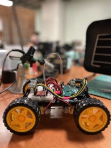
My goal is to use AI to control an arduino robot. By using a machine learning module called handsfree.js, I was able to make the bot move.
The handsfree.js machine learning module identifies two hands through a video feed. It can also predict the position and motion of the fingers and thumb. Using the position of the hands, I implemented several postures that present forward, backward, left and right. Pinching your right and left index fingers with the thumb also increases and reduces the speed of the wheels.
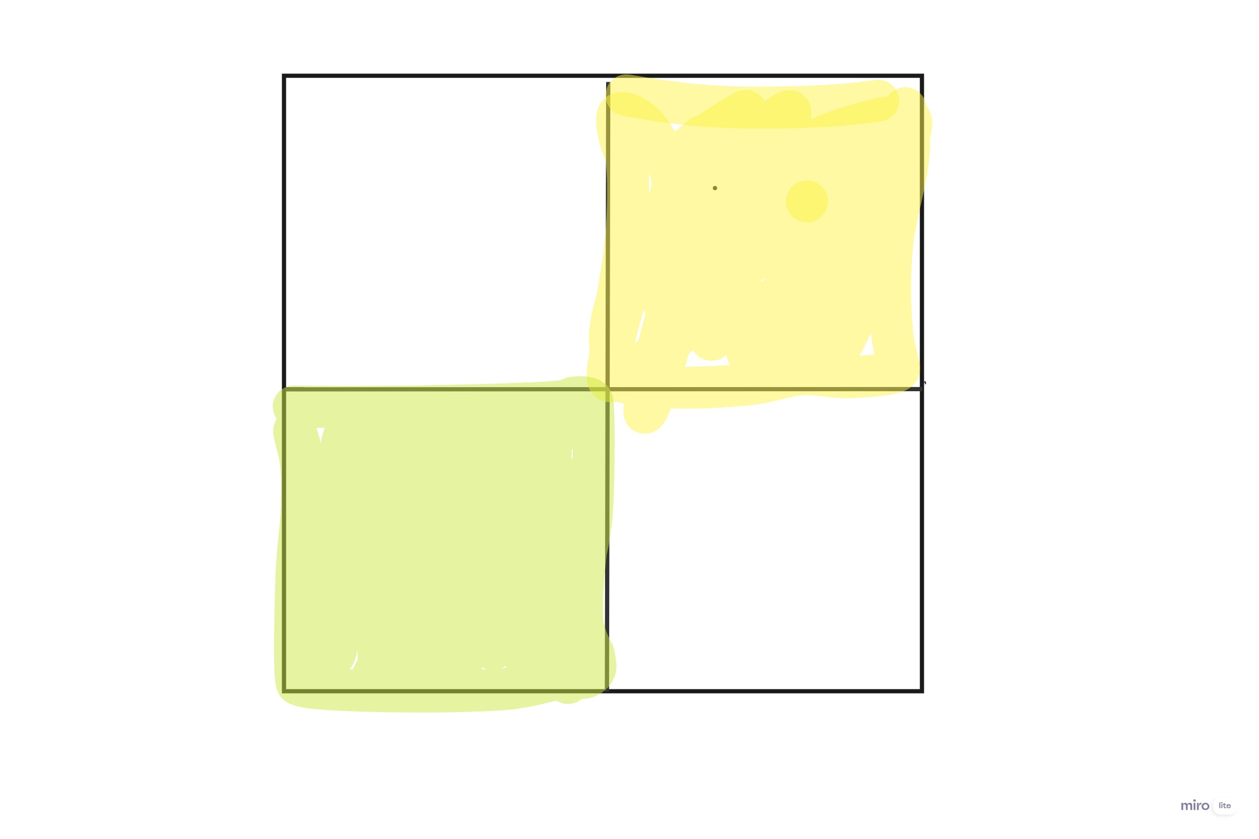
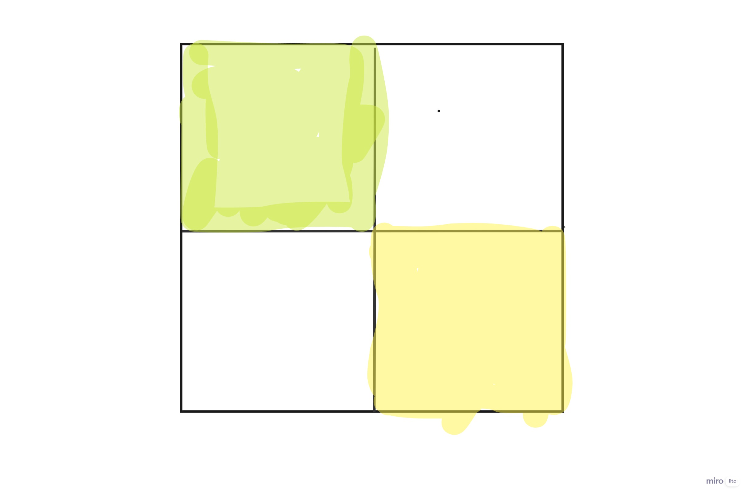
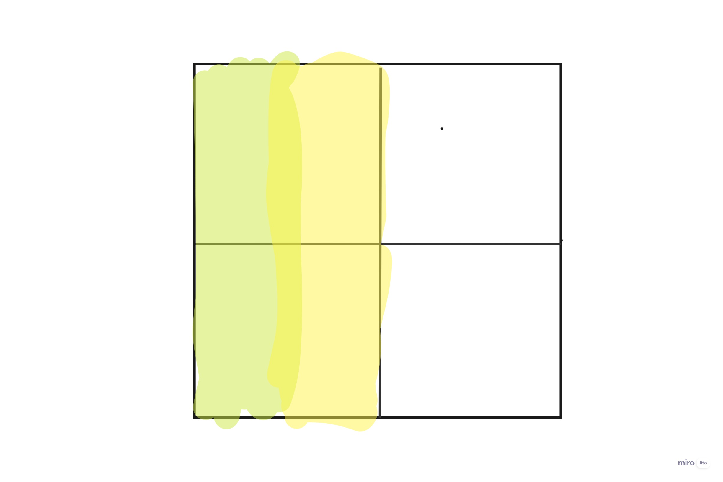
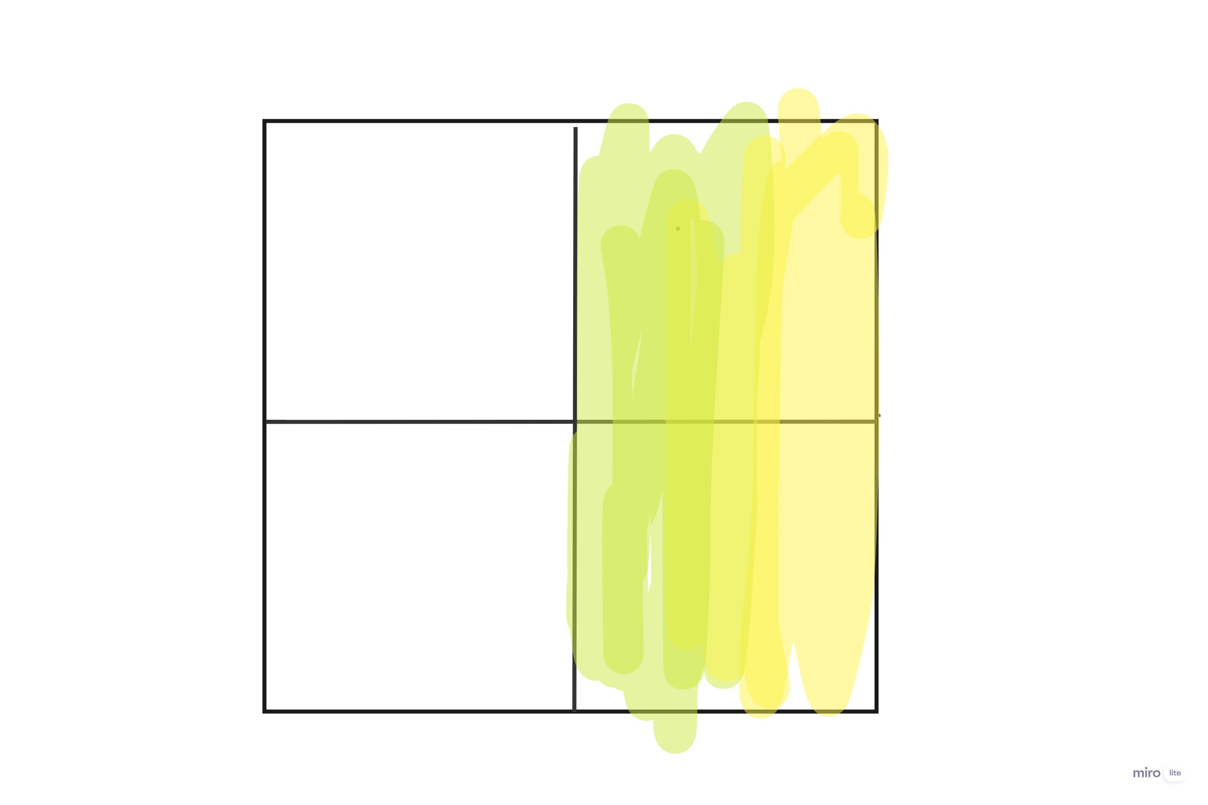
The movements are implemented on an imaginary four quadrant grid. Taking the cartesian plane as an example, to move the robot forward your right hand has to be in the first quadrant and your left hand in the third quadrant. For backward motion your left hand should be in the second quadrant and your right hand in the fourth quadrant. left movement, both hands should be in the left half of the plane and same for right movement.
Take the right hand as colored yellow and left hand as colored green. Then the movements are illustrated below:
I am finally making progress with my code but it took too long to process and figure out the bugs. it has been specifically tricky to get my full code on Arduino to understand my p5 code since i had to try many thing and innovate from things that we haven’t learned in class.
if (!serialActive) {
    text("Press Space Bar to select Serial Port", 20, 30);
  } else {
    text("Connected", 20, 30);
  }

   if (Contact2 ==1 && Contact3 ==0 && Contact4 ==0){
    Esound.play();
  }
      else if(Contact2 ==0 && Contact3 ==1 && Contact4 ==0){
        Lsound.play();
      }
      else if(Contact2 ==0 && Contact3 ==0 && Contact4 ==1){
        Dsound.play();
      }
 }
if (data != null) {
    // make sure there is actually a message
    // split the message
    let fromArduino = split(trim(data), ",");
    // if the right length, then proceed
    if (fromArduino.length == 3) {
      // only store values here
      Contact2 = fromArduino[0];
      Contact3 = fromArduino[1];
      Contact4 = fromArduino[2];
      // do everything with those values in the main draw loop
    }
hile (Serial.available()) {
    int Contact2 = Serial.parseInt();
    int Contact3 = Serial.parseInt();
    if (Serial.read() == '\n') {
      digitalWrite(2, Contact2);
      digitalWrite(5, Contact3);
      int lion = digitalRead(2);
      delay(1);
      int elephent = digitalread(3);
      delay(1);
      Serial.print(sensor);
      Serial.print(',');
      Serial.println(sensor2);
    }
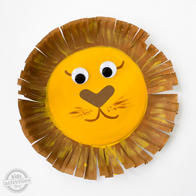
Exterior
I initially wanted to use wood to build the animals since it would have been easier but after having a talk with the professor i switched to a board that would have diffrent wires to connect the animal heads to. i went with origami animals after experimenting since they looked the cutest.
Future
I just need to fully fix my code since i cant seem to find the right balance that is needed for the project
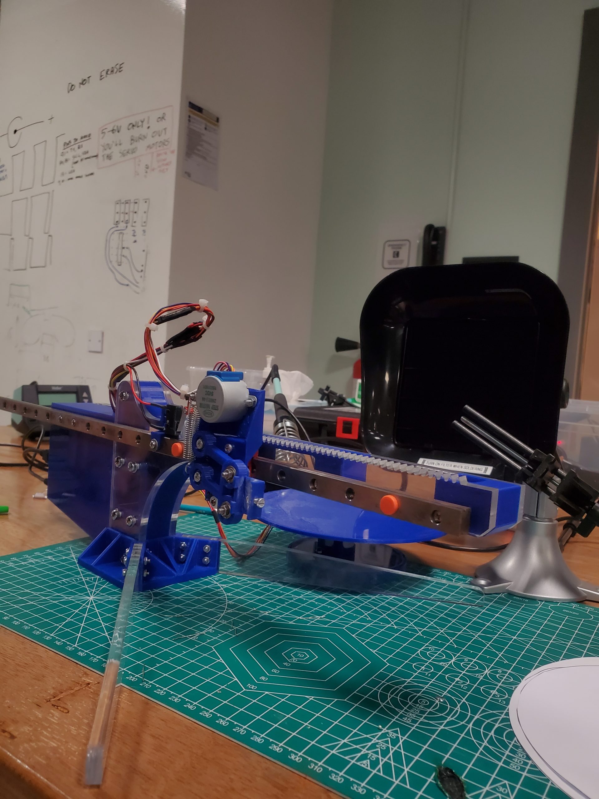
We (Samyam and Tim) designed a physical device that lets a user draw a sketch of their choice on p5.js and replicate it physically using a polar coordinate pen (plotter). In essence, the user can interact and control the device using a sketch as simple as an Archimedean spiral or as complex as a zine design of an engineering creation. It boils down to the user’s choice. Besides, the interconnectivity of the sketch, inspired by the Eulerian trial, adds to the artistic element of the system.
Drawing Platform
The project was primarily divided into four sections:
Hardware and System Design
p5.js Development
Arduino Development
Implementation and interaction between components
Hardware/ Device Design
The system comprises of a bunch of mechanical components and electrical motors that complement the functionality of the device. The device is based on a 2-DOF system in which the plotter moves to and fro on a linear rail, while the bottom plate follows the rotational motion orthogonal to the linear rail. The movement of the base plate facilitates a variety of designs, thus allowing the user to sketch any form of drawing.
First, the 3D model of the device was completed using Autodesk Fusion 360 – afterward, the components were either laser cut or 3D printed. We laser cut the rack and pinion as well as the legs of the device, while the spacer between the laser-cut components, rotating base plate and the plotter holding components were 3D printed. In addition, we have purchased a linear guide rail, step motors and stepper-motor-driver board for precision drawing. Then, all of the components, including servo motors, were assembled to complete the physical design.
The motors and the driver boards are connected to the Arduino board, which is connected to p5.js to allow the transmission of user input into the physical system.
p5.js Coding
All the p5.js coding files are divided into two main JavaScript files:
sketch.js: Contains the majority of the algorithm
keyboard_keys.js: Contains the functions to track cursor movement
In addition, there is one “p5.web-serial.js” file that contains web serial functions adapted from the public web-serial library (Link).
The majority of the device’s software design depends on the p5.js component — from storing user input to transmitting data to the Arduino in the most efficient format.
At first, the user sketches a drawing using a mouse, a trackpad or a smart stylus. The interconnectivity of the design allows the user to connect all the components of the sketch. A simple if-conditional ensures that the sketch is being drawn, thus storing cartesian coordinates of the sketch only when the different points are registered; in return, this improves the efficiency of the system together as well as restricts the possibility of redundancy and system overloading. This functionality is further dependent on manually created functions like “mousePressed()” and “mouseReleased()” that alter a boolean “isClicked” based on the status of the drawing.
Here, we have moved the origin to the center of the canvas to replicate real-life situations. All the cartesian coordinates are then stored in an array titled “Positions[]” in a vector format. Since the physical platform is based on polar coordinates, all the coordinates need to be converted to the said format. Thus, a separate function named “cartToPolar()” is written that takes cartesian x and y coordinates as arguments and returns a list containing two equivalent attributes – radius and the angle of inclination.
Here, we can see that the function receives x and y coordinates as arguments. Immediately after that, the radius is computed using a simple mathematical formula (d = (x^2 + y^2)^(0.5)), while the absolute value of the radius is determined using trigonometric relations. In order to compute the exact value of the angle, the quadrant of the coordinates is determined using a couple of if-statements and the absolute value computed above is modified. The process of altering the angle’s value is special in the first and the fourth quadrant. In the case of the first quadrant, a boolean ‘firstQuad’ is set to true and a variable ‘fullRotationNum’ is incremented that controls the rotation of the step motor fixed on the bottom plate. Similarly, in the case of the fourth quadrant, the boolean ‘fourthQuad’ is set to true and the variable ‘fullRotationNum’ is decremented. Since the rotation on a plane is calculated on a scale of 2 PI (360 degrees), this variable maintains the rotation angle without altering the motion of the step motor. Afterward, the true angle is increased based on the value of this variable.
Then the second set of if-conditionals is implemented to solve a bug in the system. Initially, without these statements, the bottom stepper motor would retract occasionally during a massive jump in the angular value, so these conditions manually compare the value of the angle with the old value stored in ‘tempAngle’ and if the jump is of a particular value, certain states of the if-conditions are executed, i.e., increasing and decreasing the value of ‘fullRotationNum’ and ‘angle’ respectively.
Finally, the radius is mapped to a scale of the maximum radius of the physical disc and the list containing two values – “mapped radius” and “modified angle” is returned to the callee function. Then, the data are transmitted to the Arduino after the user clicks the ‘SEND DATA’ button.
function button(text_, x, y, w, h) {
  // Checks if the cursor is within the button or not
  let isWithinButton =
    mouseX < x + w && mouseX > x && mouseY < y + h && mouseY > y;

  // Hover Effect
  if (isWithinButton) {
    fill(143, 148, 123);
    cursor(HAND);
  } else {
    fill("grey");
    cursor(ARROW);
  }

  // Button Setting
  stroke("black");
  strokeWeight(2);
  rect(x, y, w, h, 5);

  // Text inside the button
  textFont("Helvetica");
  stroke(5);
  textSize(25);
  fill("white");
  text(text_, x + 18, y + 32);

  // Return a boolean value
  return isWithinButton;
}
The algorithm behind the ‘SEND DATA’ button is coded manually in a function titled ‘send_data_button’. This function relies on a mother function ‘button’ that takes (1) the name of the button, (2) (3) x and y coordinates of the button and (4) (5) the height and width of the button. In order to create a hover effect, the size and color of the button are altered using if-conditions. Then, the function compares the location of the cursor with the location of the button and returns a boolean value indicating whether the cursor is inside or outside the button (true indicates inside and false indicates outside). Thus, when ‘send_data_button’ is coded, it first creates the button and then begins the data transmission process.
let first_point = false;

// Function that sends data to arduino
function send_data_button() {
  let x = canvas_w - 210;
  let y = canvas_h - 70;
  let w = 180;
  let h = 50;

  // If the cursor is within the button button() function returns 1, else 0;
  let sendBool = button("SEND DATA", x, y, w, h);

  // Sending the data if the cursor iswithin the button and mouse is clicked
  if (sendBool && mouseIsPressed && !first_point) {
    serial.write(String("H"));
    first_point = true;
    startSending = true;

    button_bool = true;
    print("Homing Machine...");


  }
  else
    button_bool = false;
}
The entire process of sending data to the Arduino depends on two boolean variables – “startSending” and “drawingFinished”. At the beginning of the transmission, a single character ‘H’ is transmitted to the Arduino in the form of a string. It indicates that the first coordinate is ready to be sent thus setting the variable ‘firstPoint’ to true inside the ‘send_data_button’ and displaying a message on the console that says ‘Homing Machine’, which essentially determines the position of the absolute origin or reference point of the plotter (it is completed every time a sketch has to be drawn). Then, the program continues inside the native draw() function.
let tmp = 1;
function draw()
{
  background(203,203,205);
  myCirc();
  instruction_txt();

  //Buttons
  send_data_button();
  reset_button();

  // Translate the origin point to the center of the screen
  translate(width/2, height/2);


  // Restricting the sketch within the canvas
  let d_comp = pow((sq(mouseX - (width/2)) + sq(mouseY - (width/2))), 0.5);
  if (isClicked && (d_comp >= (sketch_radius/2)))
  {
    // If the cursor is outside of the circle and the button, execute this condition
    if (!button_bool)
    {
      isClicked = false;
      print("Draw within the canvas!");
    }

    // If the cursor is outside of the circle but within the button, exectute this condition
    else
    {
      isClicked = false;
      print("Button clicked!");
    }

  }


  // Make sure the mouse is clicked and cursor position is different
  if (isClicked && mouseX !== pmouseX && mouseX !== pmouseY)
  {

    // Create a vector and add it to the list
    // let pt = createVector(mouseX, mouseY);          // When origin is at the top-left corner
    let pt = createVector(mouseX - width / 2, mouseY - height / 2);
    positions.push(pt);

    // Handle the case when x = 0
    if (pt.x == 0) pt.x = 0.01;

    // Mapping Cartesian to Polar and appending it in mappedPositions array
    let temp_list = [];
    temp_list = cartToPolar(pt.x, pt.y);
    let pt_mapped = createVector(temp_list[0] * one_px_mm, temp_list[1]);
    mappedPositions.push(pt_mapped);


    print("\nCounter: " + tmp);
    // Printing co-ordinates stored in the list(s)
    print("Cartesian: x: " + pt.x + " and y: " + pt.y);
    print("Polar:     r: " + pt_mapped.x + " and Angle: " + pt_mapped.y);
    tmp++;
  }

  // Draw Settings
  noFill();
  strokeWeight(5);
  strokeJoin(ROUND);

  // Go through the list of vectors and plot them
  beginShape();
  for (let i = 0; i < positions.length; i++) {
    let pt = positions[i];
    curveVertex(pt.x, pt.y);
  }
  endShape();


  // Data Transmission
  if (startSending)
  // if (startSending) {
    if (inData == "0")
    {
      let temp_var =
        str(mappedPositions[i].x) + "," + str(mappedPositions[i].y);
      let percent = int((i / mappedPositions.length) * 100);
      print("[" + percent + "% completed] " + temp_var);          // Progress on Console

      serial.write(String(temp_var));

      i += 1;


      // Check if all the points are trasmitted
      if (i == mappedPositions.length) {
        startSending = false;
        drawingFinished = true;
      }

      inData = "1";        // Reset the watch-dog variable


      if (i >= 1)
        first_point = false;
    }
  }

  // Change the settings after completing the drawing
  if (drawingFinished) {
    serial.write(String("E"));
    print("completed!");
    i = 0;

    startSending = false;
    drawingFinished = false;

    firstQuad = false;
    fourthQuad = false;
    fullRotationNum = 0;
  }
Just after plotting the points of the sketch on the p5.js canvas by looping through the cartesian list, the program checks the status of the ‘startSending’ boolean – if it is set to true and the value of value received from Arduino is ‘0’, it concatenates the radius and the angle of the point separated by a comma. This concatenated string, stored in a variable called ‘temp_var’, is sent to the Arduino (in the form of a string). This process of transmitting the entire message in the form of a string is done by calling the “String()” function of p5.js. Without this explicit call of the function, the message transmission is interrupted, thus the solution. Afterward, the status of the ‘firstPoint’ is set to false after the first coordinate has been sent. Similarly, one if-condition checks if all coordinates have been sent – when it evaluates to true, “drawingFinished” is set to true whereas “startSending” is set to false.
In addition to the functions/ methodologies described above, the program consists of a variety of serial communication functions like portConnect() and portDisconnnect() to track the physical connection between p5.js and the Arduino. At first makePortbutton() is called to create a button on the canvas that allows the user to select the wired connection. One important function is ‘serialEvent()’ function that tracks the data received from the Arduino and stores it in ‘inData’ variable. All these functions are mainly called in the setup() function and display corresponding messages on the console. Essentially, these functions facilitate the error-handling functionality of the system, thus avoiding unintended interruptions of the process.
Arduino Coding
The Arduino board is coded to control the motion of two major components in the physical system: (1) a servo motor (connected to the vertically mobile plotter) and (2) two stepper motors (connected to the linear rail and the bottom plate).
At the very beginning of the program, two libraries (AccelStepper.h and Servo.h) are loaded in the project — we will use the methods of these libraries throughout the sketching process. The system uses two stepper motors as described earlier so global variables are fixed at the beginning of the code for individual motors. Afterward, basic settings for the step motors are set up — for example, determining the MotorInterfaceType (that allows four wire connections in a half-step mode) for the step motor, creating two individual instances of stepper motor classes from the imported library (armStepper and plateStepper respectively) and creating an object of the servo class called ‘penServo’. The AccelStepper library allows us to connect multiple stepper motors with controlled acceleration and deceleration. Similarly, different global variables are instantiated that are required throughout the sketching process.
Inside the setup() function, pinModes for input and output are set up. Similarly, the maxspeed and maxAcceleration of both the stepper motors are set to 1000 steps per cycle and 200 steps per second squared respectively. Also, the name (number) of the pin attached to the servo and the control of its shaft is controlled via attach() and write() methods of the servo library.
Inside the draw() function, the program homes the machine using a manual function titled ‘homeMachine()’ that takes ‘servo angle’ as an argument. This function sets the angle of the servo to 90 and the speed of the steppers to -400. Then it checks if the value stored in ‘limitSw’ ( variable that stores input value) is ‘1’ (when the switch is pressed), the stepper attached to the plotter (arm) moves to the origin point and a reference point is established by calling a function called ‘centerPen()’ that takes servo angle as input.
In the linear rail, 0.02047 mm equals 1 step, thus using this value, the function ‘centerPen()’ moves the pen to the location of the reference point, while the value received from the argument controls the angular movement of the motor. After this function, the ‘homing’ variable is set to false marking the end of the first step.
The program then checks the data received from p5.js. If the value is “H”, homing, machineStart and firstpoint variables are set to true thus homing the machine before every sketch. Similarly, if the value is “E”, corresponding attributes are altered to facilitate different functionality of the device.
Based on the attributes set above and the data received from p5.js, the program proceeds. The message is sliced and ‘radius’ and ‘angle’ are stored in an array coordVal[].
If the firstPoint variable is set to true, the servo angle is set to 90 and both the stepper motors are moved to position 0 and the angular value is stored temporarily; in the case, it’s not the first point, the servo angle is set to 110. Then, the angular value stored in the temporary variable and in the arrays are compared, and the global variable ‘drawing’ is set to ‘false’ if the difference is greater than 90.
Afterward, the positions of the stepper motors are changed based on the values received from p5.js. Using the radius of the point, the plotter’s target position is set; also, the plate’s target position is set using the radius and halfStepToDegrees conversion. Then, if the distance(s) from the current position to the target position of both the stepper motors are 0 respectively, the drawing variable is set to true and a string ‘0’ is sent to p5.js. This way, the device moves based on the input from p5.js and a sketch is replicated on the device.
Communication between Arduino and p5.js
For this project, Arduino and p5.js communicate with one another in two ways – in other words, it is a bidirectional communication. At first, when the user clicks the “SEND DATA” button on the p5.js canvas, p5.js sends a character “H” in the form of a string followed by a series of strings in the format <radius, angle> (here brackets do not hold any significance). Once the first coordinate is sent, Arduino verifies its authenticity, and if it is a valid one, the stepper motors and the servo motor take a new position(s). Upon successful completion of the movement, Arduino sends back “0” as a string to p5.js. This instructs p5.js to send a second coordinate and so forth. This way, two-way communication takes place before sending a new set of coordinates.
Proud Aspects
The project has been a demanding undertaking. From designing hardware components and waiting for hours to get parts printed to designing the software that dictates the functioning of the device has been an arduous task. Despite the number of bugs faced, we were able to find our way through, and here is our final project.
During this time, the phase that required a notable amount of time was ‘cartToPolar(x, y)’ function that we manually coded. As described earlier, it transforms ordinates of individual cartesian coordinates into polar form since the machine understands polar coordinates only. Thus, this function was a no-brainer for the device to function. We initially coded the function based on our assumptions. However, as moved to the user-testing phase, we faced a few bugs that would not hinder the performance per se but rather would reduce the charm of the project. Thus, after hours and even days of debugging, we were able to finalize the project ideas. Now, this function controls the motion of the device. It takes a set of extremely raw values and transforms them into a value that the drawing platform understands. Besides, the function handles the extreme conditions of the radii values; this way, we were able to avoid situations where the program may crash. It took a massive amount of our time as well as Mathematics oriented brainstorming.
Similarly, building the whole platform was a task in itself. We were assembling parts built from different processes — laser cutting and 3D printing — thus, when the device took a shape, it was an eternal feeling. We were able to precisely determine its structure beforehand and correctly build its physical structure. It is something that we are definitely happy about.
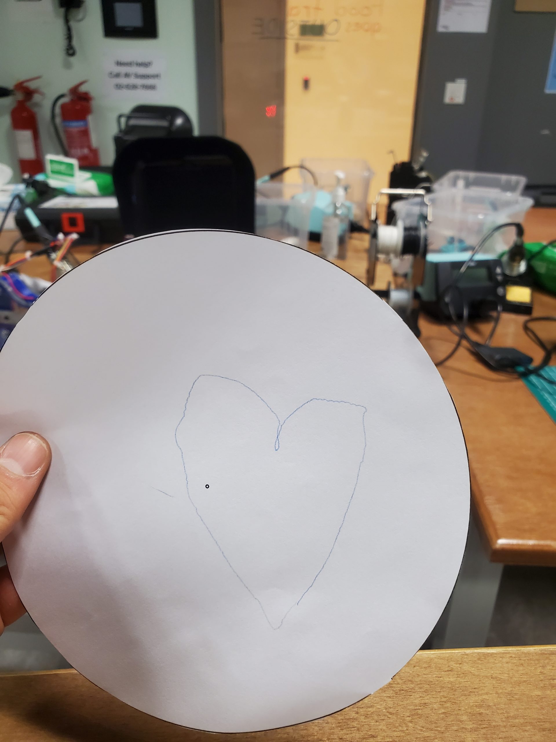
Interaction
In this project, the user is in charge of the drawing. There is a circle on the p5.js canvas; this is where the user can draw any sketch of their choice — here we are basically converting our square canvas to a circular one to replicate the base plate of the device. Once, the drawing is completed, the user can click ‘SEND DATA’ button and wait for the drawing to complete.
Future Improvements
In this project, we were able to reduce the time the device requires to draw a sketch by half. The device consists of numerous individual elements, thus after carefully redoing software algorithms, we were able to bring down the time complexity of the physical device. That said, the device still takes some time to complete the drawing. Thus, our future priority would be to reduce the time even more so that it functions at its peak speed. This could be done by recording every single point through which the cursor passes – at present, the speed of the cursor determines the number of points recorded, so this could be solved in future iterations to reduce the noise.
Similarly, the parts are 3D printed and the components we purchased belonged to a comparatively affordable category. Thus, in future iteration(s), we would build the physical components using more expensive and reliable components, thus avoiding the noise that these components catch at present. Even though the noise is negligible, at some point, the user may notice it. Thus, our priority would be to decrease the noise using high-quality components.
Individual Contribution
Task
Person
Hardware Design & Assembly
Tim
Arduino
Tim
p5.js
Samyam
Design Implementation
Samyam
Hardware + Software Communication
Both
User Testing
Both
Blogs/ Documentation and Video
Samyam
Bugs and Final Polishing
Both
Hardware Casing
Tim
Reflection
This project took a total of more than two weeks to complete — from designing its raw structure to actually building it and integrating it with the software component. Sometimes, we were stuck on a bug for days even though the idea would work theoretically, while other times, every testing would go as planned. Nevertheless, it was an interesting project and we are glad about the way the project turned out to be.
We (Samyam and Tim) designed a physical device that lets a user draw a sketch of their choice on p5.js and replicate it physically using a polar coordinate pen (plotter). In essence, the user can interact and control the device using a sketch as simple as an Archimedean spiral or as complex as a zine design of an engineering creation. It boils down to the user’s choice. Besides, the interconnectivity of the sketch, inspired by the Eulerian trial, adds to the artistic element of the system.
Drawing Platform
The project was primarily divided into four sections:
Hardware and System Design
p5.js Development
Arduino Development
Implementation and interaction between components
Hardware/ Device Design
The system comprises of a bunch of mechanical components and electrical motors that complement the functionality of the device. The device is based on a 2-DOF system in which the plotter moves to and fro on a linear rail, while the bottom plate follows the rotational motion orthogonal to the linear rail. The movement of the base plate facilitates a variety of designs, thus allowing the user to sketch any form of drawing.
First, the 3D model of the device was completed using Autodesk Fusion 360 – afterward, the components were either laser cut or 3D printed. We laser cut the rack and pinion as well as the legs of the device, while the spacer between the laser-cut components, rotating base plate and the plotter holding components were 3D printed. In addition, we have purchased a linear guide rail, step motors and stepper-motor-driver board for precision drawing. Then, all of the components, including servo motors, were assembled to complete the physical design.
The motors and the driver boards are connected to the Arduino board, which is connected to p5.js to allow the transmission of user input into the physical system.
p5.js Coding
All the p5.js coding files are divided into two main JavaScript files:
sketch.js: Contains the majority of the algorithm
keyboard_keys.js: Contains the functions to track cursor movement
In addition, there is one “p5.web-serial.js” file that contains web serial functions adapted from the public web-serial library (Link).
The majority of the device’s software design depends on the p5.js component — from storing user input to transmitting data to the Arduino in the most efficient format.
At first, the user sketches a drawing using a mouse, a trackpad or a smart stylus. The interconnectivity of the design allows the user to connect all the components of the sketch. A simple if-conditional ensures that the sketch is being drawn, thus storing cartesian coordinates of the sketch only when the different points are registered; in return, this improves the efficiency of the system together as well as restricts the possibility of redundancy and system overloading. This functionality is further dependent on manually created functions like “mousePressed()” and “mouseReleased()” that alter a boolean “isClicked” based on the status of the drawing.
Here, we have moved the origin to the center of the canvas to replicate real-life situations. All the cartesian coordinates are then stored in an array titled “Positions[]” in a vector format. Since the physical platform is based on polar coordinates, all the coordinates need to be converted to the said format. Thus, a separate function named “cartToPolar()” is written that takes cartesian x and y coordinates as arguments and returns a list containing two equivalent attributes – radius and the angle of inclination.
Here, we can see that the function receives x and y coordinates as arguments. Immediately after that, the radius is computed using a simple mathematical formula (d = (x^2 + y^2)^(0.5)), while the absolute value of the radius is determined using trigonometric relations. In order to compute the exact value of the angle, the quadrant of the coordinates is determined using a couple of if-statements and the absolute value computed above is modified. The process of altering the angle’s value is special in the first and the fourth quadrant. In the case of the first quadrant, a boolean ‘firstQuad’ is set to true and a variable ‘fullRotationNum’ is incremented that controls the rotation of the step motor fixed on the bottom plate. Similarly, in the case of the fourth quadrant, the boolean ‘fourthQuad’ is set to true and the variable ‘fullRotationNum’ is decremented. Since the rotation on a plane is calculated on a scale of 2 PI (360 degrees), this variable maintains the rotation angle without altering the motion of the step motor. Afterward, the true angle is increased based on the value of this variable.
Then the second set of if-conditionals is implemented to solve a bug in the system. Initially, without these statements, the bottom stepper motor would retract occasionally during a massive jump in the angular value, so these conditions manually compare the value of the angle with the old value stored in ‘tempAngle’ and if the jump is of a particular value, certain states of the if-conditions are executed, i.e., increasing and decreasing the value of ‘fullRotationNum’ and ‘angle’ respectively.
Finally, the radius is mapped to a scale of the maximum radius of the physical disc and the list containing two values – “mapped radius” and “modified angle” is returned to the callee function. Then, the data are transmitted to the Arduino after the user clicks the ‘SEND DATA’ button.
function button(text_, x, y, w, h) {
  // Checks if the cursor is within the button or not
  let isWithinButton =
    mouseX < x + w && mouseX > x && mouseY < y + h && mouseY > y;

  // Hover Effect
  if (isWithinButton) {
    fill(143, 148, 123);
    cursor(HAND);
  } else {
    fill("grey");
    cursor(ARROW);
  }

  // Button Setting
  stroke("black");
  strokeWeight(2);
  rect(x, y, w, h, 5);

  // Text inside the button
  textFont("Helvetica");
  stroke(5);
  textSize(25);
  fill("white");
  text(text_, x + 18, y + 32);

  // Return a boolean value
  return isWithinButton;
}
The algorithm behind the ‘SEND DATA’ button is coded manually in a function titled ‘send_data_button’. This function relies on a mother function ‘button’ that takes (1) the name of the button, (2) (3) x and y coordinates of the button and (4) (5) the height and width of the button. In order to create a hover effect, the size and color of the button are altered using if-conditions. Then, the function compares the location of the cursor with the location of the button and returns a boolean value indicating whether the cursor is inside or outside the button (true indicates inside and false indicates outside). Thus, when ‘send_data_button’ is coded, it first creates the button and then begins the data transmission process.
let first_point = false;

// Function that sends data to arduino
function send_data_button() {
  let x = canvas_w - 210;
  let y = canvas_h - 70;
  let w = 180;
  let h = 50;

  // If the cursor is within the button button() function returns 1, else 0;
  let sendBool = button("SEND DATA", x, y, w, h);

  // Sending the data if the cursor iswithin the button and mouse is clicked
  if (sendBool && mouseIsPressed && !first_point) {
    serial.write(String("H"));
    first_point = true;
    startSending = true;

    button_bool = true;
    print("Homing Machine...");


  }
  else
    button_bool = false;
}
The entire process of sending data to the Arduino depends on two boolean variables – “startSending” and “drawingFinished”. At the beginning of the transmission, a single character ‘H’ is transmitted to the Arduino in the form of a string. It indicates that the first coordinate is ready to be sent thus setting the variable ‘firstPoint’ to true inside the ‘send_data_button’ and displaying a message on the console that says ‘Homing Machine’, which essentially determines the position of the absolute origin or reference point of the plotter (it is completed every time a sketch has to be drawn). Then, the program continues inside the native draw() function.
let tmp = 1;
function draw()
{
  background(203,203,205);
  myCirc();
  instruction_txt();

  //Buttons
  send_data_button();
  reset_button();

  // Translate the origin point to the center of the screen
  translate(width/2, height/2);


  // Restricting the sketch within the canvas
  let d_comp = pow((sq(mouseX - (width/2)) + sq(mouseY - (width/2))), 0.5);
  if (isClicked && (d_comp >= (sketch_radius/2)))
  {
    // If the cursor is outside of the circle and the button, execute this condition
    if (!button_bool)
    {
      isClicked = false;
      print("Draw within the canvas!");
    }

    // If the cursor is outside of the circle but within the button, exectute this condition
    else
    {
      isClicked = false;
      print("Button clicked!");
    }

  }


  // Make sure the mouse is clicked and cursor position is different
  if (isClicked && mouseX !== pmouseX && mouseX !== pmouseY)
  {

    // Create a vector and add it to the list
    // let pt = createVector(mouseX, mouseY);          // When origin is at the top-left corner
    let pt = createVector(mouseX - width / 2, mouseY - height / 2);
    positions.push(pt);

    // Handle the case when x = 0
    if (pt.x == 0) pt.x = 0.01;

    // Mapping Cartesian to Polar and appending it in mappedPositions array
    let temp_list = [];
    temp_list = cartToPolar(pt.x, pt.y);
    let pt_mapped = createVector(temp_list[0] * one_px_mm, temp_list[1]);
    mappedPositions.push(pt_mapped);


    print("\nCounter: " + tmp);
    // Printing co-ordinates stored in the list(s)
    print("Cartesian: x: " + pt.x + " and y: " + pt.y);
    print("Polar:     r: " + pt_mapped.x + " and Angle: " + pt_mapped.y);
    tmp++;
  }

  // Draw Settings
  noFill();
  strokeWeight(5);
  strokeJoin(ROUND);

  // Go through the list of vectors and plot them
  beginShape();
  for (let i = 0; i < positions.length; i++) {
    let pt = positions[i];
    curveVertex(pt.x, pt.y);
  }
  endShape();


  // Data Transmission
  if (startSending)
  // if (startSending) {
    if (inData == "0")
    {
      let temp_var =
        str(mappedPositions[i].x) + "," + str(mappedPositions[i].y);
      let percent = int((i / mappedPositions.length) * 100);
      print("[" + percent + "% completed] " + temp_var);          // Progress on Console

      serial.write(String(temp_var));

      i += 1;


      // Check if all the points are trasmitted
      if (i == mappedPositions.length) {
        startSending = false;
        drawingFinished = true;
      }

      inData = "1";        // Reset the watch-dog variable


      if (i >= 1)
        first_point = false;
    }
  }

  // Change the settings after completing the drawing
  if (drawingFinished) {
    serial.write(String("E"));
    print("completed!");
    i = 0;

    startSending = false;
    drawingFinished = false;

    firstQuad = false;
    fourthQuad = false;
    fullRotationNum = 0;
  }
Just after plotting the points of the sketch on the p5.js canvas by looping through the cartesian list, the program checks the status of the ‘startSending’ boolean – if it is set to true and the value of value received from Arduino is ‘0’, it concatenates the radius and the angle of the point separated by a comma. This concatenated string, stored in a variable called ‘temp_var’, is sent to the Arduino (in the form of a string). This process of transmitting the entire message in the form of a string is done by calling the “String()” function of p5.js. Without this explicit call of the function, the message transmission is interrupted, thus the solution. Afterward, the status of the ‘firstPoint’ is set to false after the first coordinate has been sent. Similarly, one if-condition checks if all coordinates have been sent – when it evaluates to true, “drawingFinished” is set to true whereas “startSending” is set to false.
In addition to the functions/ methodologies described above, the program consists of a variety of serial communication functions like portConnect() and portDisconnnect() to track the physical connection between p5.js and the Arduino. At first makePortbutton() is called to create a button on the canvas that allows the user to select the wired connection. One important function is ‘serialEvent()’ function that tracks the data received from the Arduino and stores it in ‘inData’ variable. All these functions are mainly called in the setup() function and display corresponding messages on the console. Essentially, these functions facilitate the error-handling functionality of the system, thus avoiding unintended interruptions of the process.
Arduino Coding
The Arduino board is coded to control the motion of two major components in the physical system: (1) a servo motor (connected to the vertically mobile plotter) and (2) two stepper motors (connected to the linear rail and the bottom plate).
At the very beginning of the program, two libraries (AccelStepper.h and Servo.h) are loaded in the project — we will use the methods of these libraries throughout the sketching process. The system uses two stepper motors as described earlier so global variables are fixed at the beginning of the code for individual motors. Afterward, basic settings for the step motors are set up — for example, determining the MotorInterfaceType (that allows four wire connections in a half-step mode) for the step motor, creating two individual instances of stepper motor classes from the imported library (armStepper and plateStepper respectively) and creating an object of the servo class called ‘penServo’. The AccelStepper library allows us to connect multiple stepper motors with controlled acceleration and deceleration. Similarly, different global variables are instantiated that are required throughout the sketching process.
Inside the setup() function, pinModes for input and output are set up. Similarly, the maxspeed and maxAcceleration of both the stepper motors are set to 1000 steps per cycle and 200 steps per second squared respectively. Also, the name (number) of the pin attached to the servo and the control of its shaft is controlled via attach() and write() methods of the servo library.
Inside the draw() function, the program homes the machine using a manual function titled ‘homeMachine()’ that takes ‘servo angle’ as an argument. This function sets the angle of the servo to 90 and the speed of the steppers to -400. Then it checks if the value stored in ‘limitSw’ ( variable that stores input value) is ‘1’ (when the switch is pressed), the stepper attached to the plotter (arm) moves to the origin point and a reference point is established by calling a function called ‘centerPen()’ that takes servo angle as input.
In the linear rail, 0.02047 mm equals 1 step, thus using this value, the function ‘centerPen()’ moves the pen to the location of the reference point, while the value received from the argument controls the angular movement of the motor. After this function, the ‘homing’ variable is set to false marking the end of the first step.
The program then checks the data received from p5.js. If the value is “H”, homing, machineStart and firstpoint variables are set to true thus homing the machine before every sketch. Similarly, if the value is “E”, corresponding attributes are altered to facilitate different functionality of the device.
Based on the attributes set above and the data received from p5.js, the program proceeds. The message is sliced and ‘radius’ and ‘angle’ are stored in an array coordVal[].
If the firstPoint variable is set to true, the servo angle is set to 90 and both the stepper motors are moved to position 0 and the angular value is stored temporarily; in the case, it’s not the first point, the servo angle is set to 110. Then, the angular value stored in the temporary variable and in the arrays are compared, and the global variable ‘drawing’ is set to ‘false’ if the difference is greater than 90.
Afterward, the positions of the stepper motors are changed based on the values received from p5.js. Using the radius of the point, the plotter’s target position is set; also, the plate’s target position is set using the radius and halfStepToDegrees conversion. Then, if the distance(s) from the current position to the target position of both the stepper motors are 0 respectively, the drawing variable is set to true and a string ‘0’ is sent to p5.js. This way, the device moves based on the input from p5.js and a sketch is replicated on the device.
Communication between Arduino and p5.js
For this project, Arduino and p5.js communicate with one another in two ways – in other words, it is a bidirectional communication. At first, when the user clicks the “SEND DATA” button on the p5.js canvas, p5.js sends a character “H” in the form of a string followed by a series of strings in the format <radius, angle> (here bracket do not hold any significance). Once the first coordinate is sent, Arduino verifies its authenticity, and if it is a valid one, the stepper motors and the servo motor take a new position(s). Upon successful completion of the movement, Arduino sends back “0” as a string to p5.js. This instructs p5.js to send a second coordinate and so forth. This way, two-way communication takes place before sending a new set of coordinates.
Proud Aspects
The project has been a demanding undertaking. From designing hardware components and waiting for hours to get parts printed to designing the software that dictates the functioning of the device has been an arduous task. Despite the number of bugs faced, we were able to find our way through, and here is our final project.
During this time, the phase that required a notable amount of time was ‘cartToPolar(x, y)’ function that we manually coded. As described earlier, it transforms ordinates of individual cartesian coordinates into polar form since the machine understands polar coordinates only. Thus, this function was a no-brainer for the device to function. We initially coded the function based on our assumptions. However, as moved to the user-testing phase, we faced a few bugs that would not hinder the performance per se but rather would reduce the charm of the project. Thus, after hours and even days of debugging, we were able to finalize the project ideas. Now, this function controls the motion of the device. It takes a set of extremely raw values and transforms them into a value that the drawing platform understands. Besides, the function handles the extreme conditions of the radii values; this way, we were able to avoid situations where the program may crash. It took a massive amount of our time as well as Mathematics oriented brainstorming.
Similarly, building the whole platform was a task in itself. We were assembling parts built from different processes — laser cutting and 3D printing — thus, when the device took a shape, it was an eternal feeling. We were able to precisely determine its structure beforehand and correctly build its physical structure. It is something that we are definitely happy about.
Interaction
In this project, the user is in charge of the drawing. There is a circle on the p5.js canvas; this is where the user can draw any sketch of their choice — here we are basically converting our square canvas to a circular one to replicate the base plate of the device. Once, the drawing is completed, the user can click ‘SEND DATA’ button and wait for the drawing to complete.
Future Improvements
In this project, we were able to reduce the time the device requires to draw a sketch by half. The device consists of numerous individual elements, thus after carefully redoing software algorithms, we were able to bring down the time complexity of the physical device. That said, the device still takes some time to complete the drawing. Thus, our future priority would be to reduce the time even more so that it functions at its peak speed. This could be done by recording every single point through which the cursor passes – at present, the speed of the cursor determines the number of points recorded, so this could be solved in future iterations to reduce the noise.
Similarly, the parts are 3D printed and the components we purchased belonged to a comparatively affordable category. Thus, in future iteration(s), we would build the physical components using more expensive and reliable components, thus avoiding the noise that these components catch at present. Even though the noise is negligible, at some point, the user may notice it. Thus, our priority would be to decrease the noise using high-quality components.
Individual Contribution
Task
Person
Hardware Design & Assembly
Tim
Arduino
Tim
p5.js
Samyam
Design Implementation
Samyam
Hardware + Software Communication
Both
User Testing
Both
Blogs/ Documentation and Video
Samyam
Bugs and Final Polishing
Both
Hardware Casing
Tim
Reflection
This project took a total of more than two weeks to complete — from designing its raw structure to actually building it and integrating it with the software component. Sometimes, we were stuck on a bug for days even though the idea would work theoretically, while other times, every testing would go as planned. Nevertheless, it was an interesting project and we are glad about the way the project turned out to be.
Our original idea was to create a set of friendship touch-lamps, where two lamps would be able to “communicate” with each other with the tap of a finger. Using p5 as our “remote controller”, each party would be able to choose the settings of the light they would like to send, ie. the color and the light patten. We wanted to include wireless communication in our project to stick with the vision that any two users, regardless of time, location, and proximity, would be able to communicate with that special someone through something that was visually compelling, and that the simple act of sending lights to one another might foster some other type of communication.
IMPLEMENTATION
We believe that we stuck relatively closely to our original proposal, except that due to time and challenges with serial communication, we were not able to achieve this dual communication between two Arduino devices. Hence, although we were not able to achieve interaction from user to user, we were able to achieve interaction between user, lamp, and computer.
The conversation begins with the user interacting with p5. As mentioned above, our p5.js sketch acts as the “controller” of the lamp, providing animations and small game elements that make the programming more interesting. For example, in the second scene of the sketch, the user sees a heart flashing different colors in the center of the screen and is instructed to press the keyboard when the heart flickers to a color of their liking:
Additionally, in the following screen, the sketch displays 3 different light modes to choose from: flicker, wave, and pulse. above those 3 buttons is a corresponding icon that animates that is made to mimic the specific light mode:
Throughout the p5 program, data about the user’s choices are held in three important variables: picker.color, lightMode, and inData. picker.color is an instance variable of the colorPicker class, which was coded to build the flashing heart described above. It is initially set to a null value and is set once the user presses any key to choose their color. Similarly, lightMode is a variable made to hold an integer of 0, 1, or 2 which correspond to flicker, wave, and pulse respectfully. Initially set to a null value, it becomes set when the user presses the flicker, wave, or pulse button in the screen described above. We chose to have lightMode hold an integer, though it is more confusing the the reader, makes it easier to send it as serial data. The inData variable contains the data sent from Arduino through the serial.read() function, and sends a 0 or 1, depending on whether the touch sensor on the lamp has been touched or not touched. This code from Arduino is shown below:
Finally, the conversation shifts between user-computer to user-lamp in the last screen of the p5 program (shown below), where it asks the user to touch the lamp in order to let p5.js know that it is “ready” to send the data to Arduino — “ready” meaning that inData is 1, the lightMode has been set, and picker.color has been set. The code that sends the serial data is also shown below:
if (inData == 1) {
  // console.log('the color you chose:', colorValue);
  // console.log('the light mode you chose:', lightMode);
  console.log(inData);
  let r = red(picker.color);
  let g = green(picker.color);
  let b = blue(picker.color);


  let sendToArduino = r + "," + g + "," + b + "," + lightMode + "\n";
  serial.write(sendToArduino);
Once the data is sent, the “control” of the entire system is handed over to our Arduino code, which is the code that actually displays the lights, completing the final part of the user-lamp conversation. First, after reading the data from p5, it parses the data and organizes it into variables that hold the red, green, and blue color values, as well as the light mode, similar to how it is organized in p5:
while(Serial.available()){
  sensorState = LOW;
  R = Serial.parseInt();
  G = Serial.parseInt();
  B = Serial.parseInt();
  //lightMode = Serial.read();
  lightMode = Serial.parseInt();

  if(Serial.read() == '\n'){
    Serial.write(0);
  }
}
Then, it uses those variables to create the different light modes (described in more detail in the previous posts):
  if (lightMode == 2){
  // WAVY
  //turn pixels to green one by one with delay between each pixel
  for (int pixel = 0; pixel < NUM_PIXELS; pixel++) { // for each pixel
    NeoPixel.setPixelColor(pixel, NeoPixel.Color(R, G, B)); // it only takes effect if pixels.show() is called

    NeoPixel.show();   // send the updated pixel colors to the NeoPixel hardware.
    NeoPixel.clear();

    delay(100); // pause between each pixel
  }

  // turn off all pixels for two seconds
  NeoPixel.clear();
  NeoPixel.show(); // send the updated pixel colors to the NeoPixel hardware.
  delay(10);     // off time
}

if (lightMode == 1) {
// FLICKERING:
  //turn on all pixels to red at the same time for two seconds
  for (int pixel = 0; pixel < NUM_PIXELS; pixel++) { // for each pixel
    NeoPixel.setPixelColor(pixel, NeoPixel.Color(R, G, B)); // it only takes effect if pixels.show() is called
  }
  NeoPixel.show(); // send the updated pixel colors to the NeoPixel hardware.
  delay(1000);     // on time

  // turn off all pixels for two seconds
  NeoPixel.clear();
  NeoPixel.show(); // send the updated pixel colors to the NeoPixel hardware.
  delay(500);     // off time
}

if (lightMode == 3){
  //PULSING
  uint16_t j;

  for (j = 0; j < 255; j++) {
    for (int pixel= 0; pixel < NUM_PIXELS; pixel++) {
      NeoPixel.setPixelColor(pixel, R, G, B);
      NeoPixel.setBrightness(j);
    }
    NeoPixel.show();
    delay(20);
  }

  for (j = 255; j > 0; j--) {
    for (int pixel = 0; pixel < NUM_PIXELS; pixel++) {
      NeoPixel.setPixelColor(pixel, R, G, B);
      NeoPixel.setBrightness(j);
      }
    NeoPixel.show();
    delay(20);
    Serial.println(j);
    }
  delay(100);
  //make sure to set all pixels back to full brightness for the other modes
   for (int pixel = 0; pixel < NUM_PIXELS; pixel++) {
    NeoPixel.setBrightness(255);
  }
}
Note that once the lights are displayed, the data being written out to p5 is that the lamp is not-touched and is ready for the next round of data to be collected from p5. The user has the option to stop there, or can repeat the “cycle” as many times they wish by clicking the “send another” button in p5.
WHAT WE’RE PROUD OF
Something we like about our system that we think enhances the experience is the attention to detail and aesthetic of the p5 sketch. We chose the name “Distance makes the Heart and Glow Fonder” because it is not only a cute play on words, but also keeps with our neon theme. We also wanted all of our text and images to have flickering effect and a glowing effect (reference: https://www.youtube.com/watch?v=iIWH3IUYHzM) to mimic real life neon signs and lights. Also, we felt that adding animations to the screen that shows the light modes not only made it more visually compelling but more intuitive for the user, given that the instructions of the program are minimal.
Though none of us have much experience with building, we wanted to push ourselves beyond the Arduino board we were given and try our best to make a lamp that didn’t look so obviously “Arduino”. Overall we are very happy with how it turned out, considering the time and resources we had. Everything we used to build it was made out of scrap materials found in the lab, and each part of the lamp is detachable by velcro, making it extremely easy to access the wiring and adjust things if needed.
FUTURE IMPORVEMENTS
In terms of the physical lamp, it would be nice to completely cover the wiring at the bottom with more acrylic panels. Perhaps remaking it using a different glue will also help get rid of the fogging happening on the current model.
In terms of our code, we would like to carry out our initial vision and create two lamps that can communicate with each other, and perhaps even have them communicate wirelessly.
DEMO
Below are some demo videos of our project.
MY PART
Things I contributed to the project:
did the main bulk of brainstorming and coming up with the two ideas we proposed in class, in the end went with my second idea (the lamps) as I was receiving little feedback and reciprocation from my partner’s end
initiated each time we planned to meet and work on the project
wrote 90% of all blog posts. – first post written all by me, second post written mostly by me with except for the sections “The role of Arduino” and “communication”, third blog post I wrote the “solution” section and was the one who came up with the solution and implemented it individually
wrote 100% of the p5 sketch
wrote all the code that managed the serial communication, in p5 and Arduino with the exception of the parsing integers, wrote the code for the touch sensor
with the exception of soldering 3 wires and cutting 2 triangle pieces of acrylic, came up with the design of the lamp and built the entire structure alone
was constantly debugging alone in the lab and asking for help from lab assistants, especially when it came to solving the serial communication errors.
After over two weeks of drawing, coding, testing, and fighting bugs, I finally finished my game Haluhalo!! I’m really proud of what I’ve achieved.
Project Description
In Haluhalo, you get to make haluhalo: one of my favorite classic Filipino desserts. This sweet, cold treat is made up of of all sorts of ingredients: beans, coconut jelly, fruit jellies, tapioca pearls (sago), fruits, and preserves that are mixed with crushed ice, milk, and simple syrup and topped off with ube ice cream and chocolate wafer sticks. You play by in three stages: cooking the tapioca pearls by manipulating the temperature with a potentiometer, catching the many ingredients with Posenet tracking, and blending up the milk and ice mixture with a button.
Coding
There were two challenging parts of the process. The first was debugging, which is always a bit frustrating, and the second was refactoring and restructuring the code so that it was less prone to breaking and easier to edit. This was particularly important because the code uses webserial and p5.js, as well as snippets from my previous projects, so it ended up being 800+ lines long before I started paring it down.
Below is a snippet of me using gamestates and outcomes to move between functions.
During this project, I had a long, annoying hurdle with sound and music and another separate issue with the tutorial screens that ended up being solved by a simple if else loop and a function. Sometimes, complex problems really have simple solutions.
Working on the code for this project reminded me that coding isn’t about typing up everything as quickly as possible. In fact, that method takes way more time than planning ahead. It’s better to think carefully about your structure before implementing so you can maximize the use of variables, functions, and classes rather than hardcoding what you need.
Design and Illustration
My favorite part of this project was making the designs and illustrations I made for the game. I worked hard to make them distinct, organic, and really cohesive rather than the usual stuff that we end up importing and drawing with p5.js. It took a lot more time than normally just importing images, but I think that it’s worth it.
I’ve already shown a lot of images of the designs, so here’s just one last picture of me playing + a video of the final demo! I’m really happy with this screen in particular because the sidebar on the right serves a triple purpose: it shortens the otherwise ultrastretched screen, introduces the haluhalo ingredients, and teaches the user that they have to get all eight ingredients before they can proceed. No tutorial instructions needed!
When I came into this class, I really wanted to focus on making games and experiences that were user-friendly, fun, and distinctly playful. Since I have some background in CS, I actually wanted to take a break from a lot of heavy coding, and instead try to play more with design and UI, which I think I succeeded with through this final project.
I ended up not adding more of the flairs and add-ons I envisioned, which was a great decision. Originally, I tried out using servos to move around a haluhalo cup, some soldered strings of lights, and a piezo buzzer, but realized that they would just distract from the overall experience, so I took them out. I also cut out unnecessary filler scenes to cut the game down to a 1-2 minute experience. With the extra time, I was able to refine the user experience and making the game more playable, convenient, and less prone to breakage, especially because the hardware is relatively simple.
All in all, I’m excited to show the game for the IM Showcase! Thank you to everyone for an awesome semester. I learned a lot and got to work on a lot of cool things. 🙂
Disclaimer: the title is a little deceiving – I’m not 90% done (more like 60%) yet, but I’ll hopefully get there by the end of this week!
My initial outline of completing this project was finishing the physical constructing part (the Arduino) and then moving onto the coding (p5.js), but I ended up jumping between both of them instead.
Since my first very rough brainstorm post about my gingerbread man game, I’ve made a lot of adjustments, additions, and progress in general. In this post, I will report my progress by dividing it into two: the p5.js part and the Arduino part.
P5.js:
The game (only the coding part) that I have so far can be shown here.
For the coding part of my game, I consulted my good ol’ friend Daniel Shiffman’s “Chrome Dinosaur Game” tutorial that I found on his website (here’s the link). Thankfully, his tutorial didn’t encompass any groundbreaking new skills that I had no idea about, so it was mostly for me to review and refresh my memory because it’s been a while since I have coded games on p5.js. I also was able to get access to these two links (https://www.jsdelivr.com/?docs=gh and https://github.com/bmoren/p5.collide2D#colliderectrect), from which I got directory listing and learned about the function “collideRectRect” respectively. One thing that was particularly interesting/new for me was constructing the chimneys as obstacles and also animating the gingerbread man; it was fun to set up a movement for both the chimneys (along the x axis) and the gingerbread man (along the y axis), and control the level of jump, gravity, etc. I also couldn’t really find any chimney illustrations that fitted my vision, so I ended up drawing them and uploading the pictures myself.
I’d say my code highlights are adding animation/movement to the chimneys, which can be shown below:
These were some of the struggles I’ve faced with p5.js:
Adjusting the “collideRectRect()” function – it was hard to get the perfect measurement of both the chimneys and the gingerbread man’s image boundaries and set it so that the unnecessary empty spaces that surrounds the actual illustrations acted as the “collision points,” thus making it hard for the user to aim the gingerbread man’s jumping.
Constantly shifting + playing around with the “jump” function of the gingerbread man, as well as gravity.
Arduino:
Here are some sources that I’ve used to aid my process of making a physical game controller with Arduino:
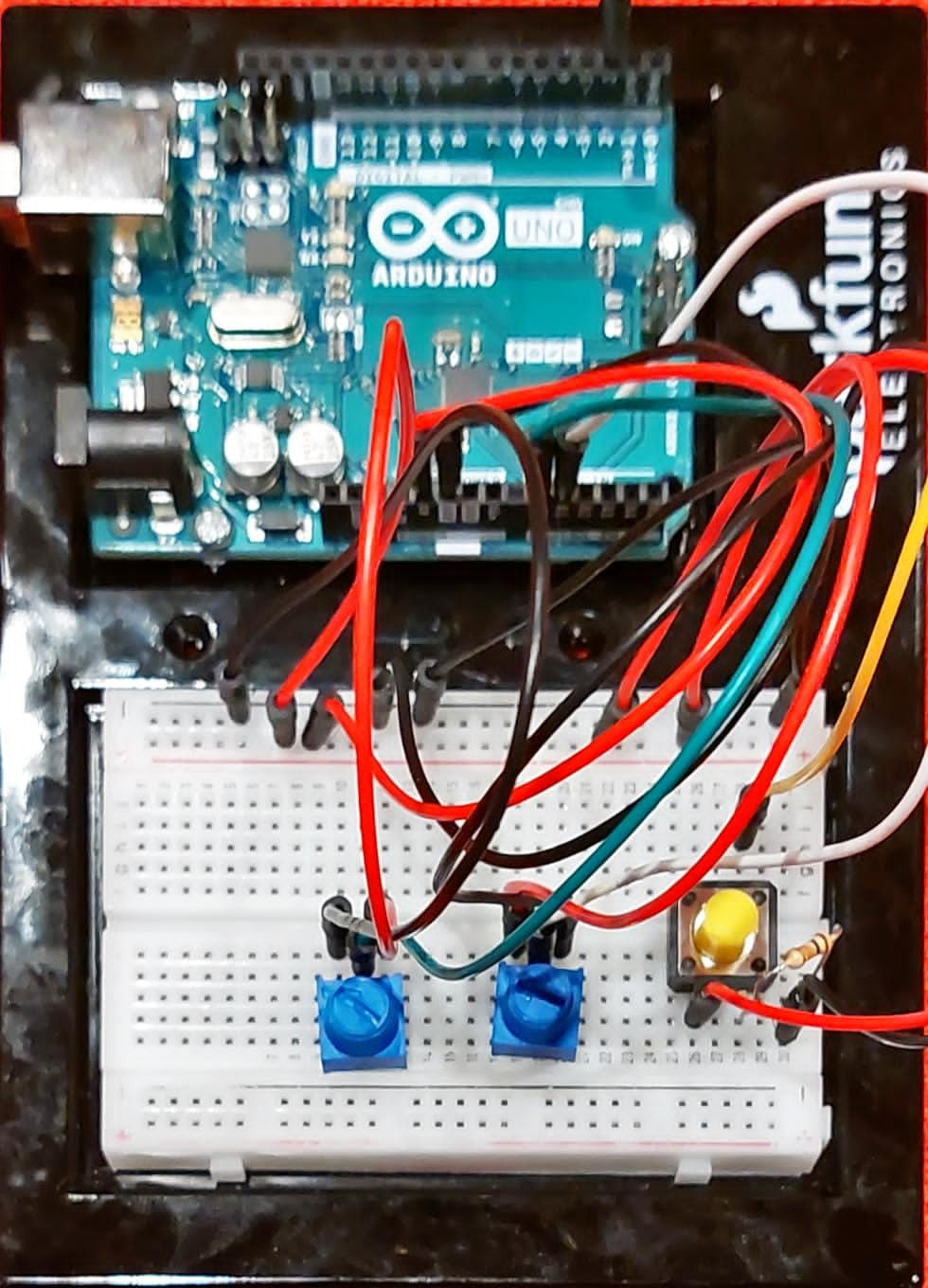
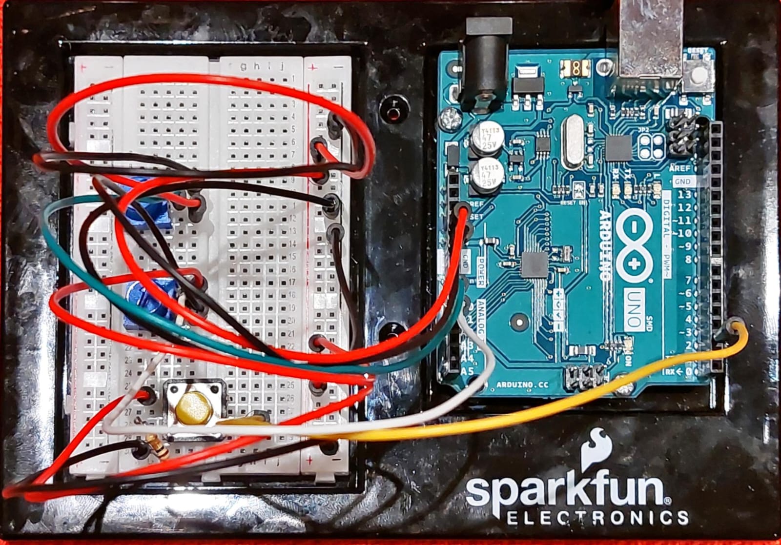
Following my last blog post, I am nearly done with my project. As of now the setup of the Arduino consists of two potentiometers that function as the dials of my etch-a-sketch and a switch that provides a clean slate to the user once they are done and want to start over.
Screenshots of the Arduino setup-
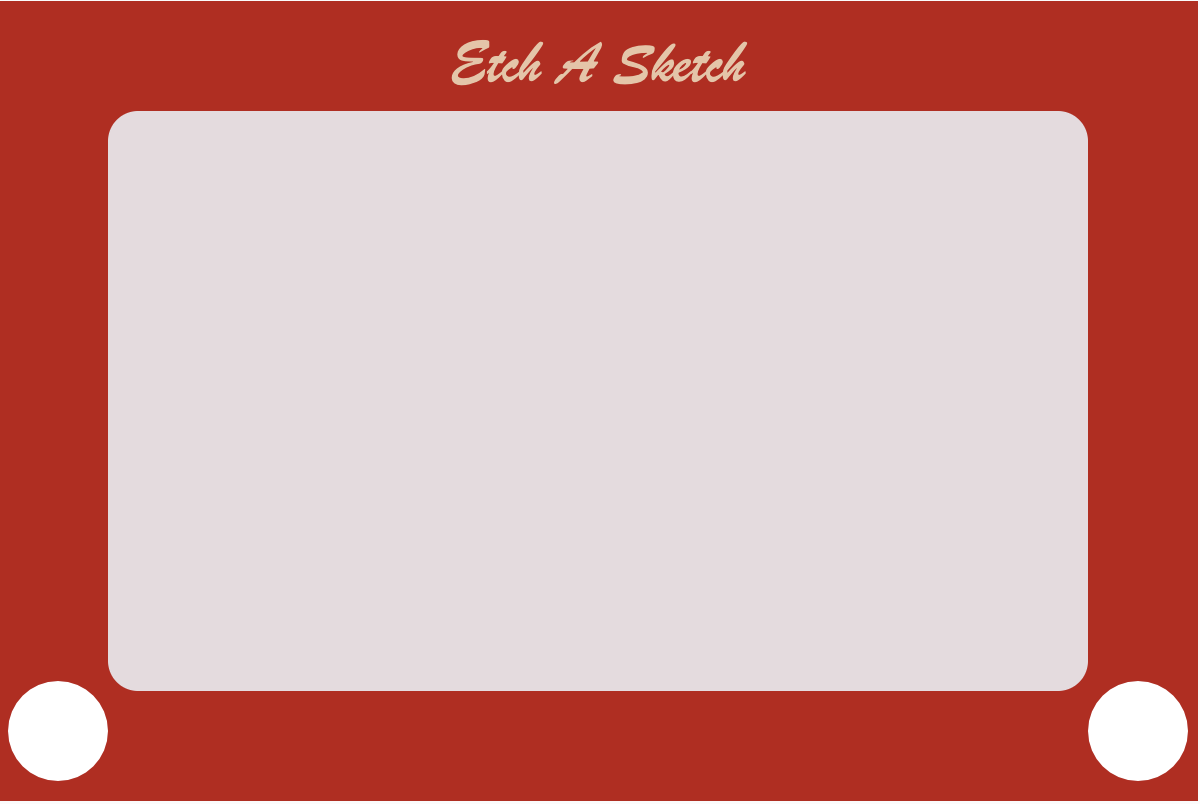
I have also designed the interface of the p5js sketch, giving it a sense of the authentic playfulness that an etch-a-sketch symbolizes.
I have also looped in a playful audio that excites the user to stay stuck and keep working on the sketch. moreover, I am pretty happy with the way the potentiometers toggle with the alpha values of the strokes that are drawn as they lend it a sort of outlook of an actual sketch being drawn on the screen.
P5js Sketch:
User Testing
I think user testing was quite an important part of the project as it allowed me to think about improving on quite a few things to make the project even more interactive and user-friendly. First off the potentiometers are placed quite close to each other on the board which makes the movement a bit restrictive for the user. Secondly, the wiring keeps on shifting at times which makes strokes appear randomly on the board as opposed to where the user wants them to go. and lastly, the switch is in between the wires which disturbs the user when they want to clean the slate.
User Testing Video:
Improvements
I am currently working on designing a better console for the game so that the project becomes more efficient. Time permitting I shall also like to include another color component in my sketch be it in terms of another stroke of my pen or pixelating the screen before clearing it to add another animated component to the sketch.