Using Sensors To Control LED Output

Concept:

My idea was to use the photoresistor as an analog sensor to control how a group of LEDs display. With a decrease in resistance as a result of lumen capacity, the photoresistor controls the LEDs to output a pattern of light displays which spells “ON”. Whereas with high resistance due to less lumen capacity, the LEDs output in a pattern which spells “OFF” with a missing F due to space.

The change between “ON” and “OFF” is controlled by two LEDs which read the analog value of the photoresistor and output a scaled down value of it.

The code:


int g1 = 12;
int g2 = 11;
int fOn = 8;
int fOff = 7;
int sens = A0;
int sensVal;
int ledval;

void setup() {
  // put your setup code here, to run once:
  pinMode(g1, OUTPUT);
  pinMode(g2, OUTPUT);
  pinMode(A0, INPUT);
  Serial.begin(9600);
}

void loop() {
  // put your main code here, to run repeatedly:
  sensVal = analogRead(sens);
  ledval = (255./1023.) * sensVal;
  Serial.println(sensVal);
  delay(250);
  if(sensVal < 200){
    digitalWrite(g1, HIGH);
    digitalWrite(g2, HIGH);
    analogWrite(fOn, ledval);
    digitalWrite(fOff, LOW);
  }
  else{
    digitalWrite(g1, HIGH);
    digitalWrite(g2, HIGH);
    analogWrite(fOff, ledval);
    digitalWrite(fOn, LOW);
  }
  
}

The “ON” state display:

The “OFF” state display:


When the lights are on the leds display on and when the lights are off the leds display off.

The video demonstration:


Reflections:

It was challenging to set up the LEDs group them together to display. With a little try and error and schematic, I got them to work. I plan to add sound and other output signals to signify when the lights are out.


My attempt at adding sound:

Week 9: Analog & digital sensors

Concept

For this assignment we were required to get information from at least one analog sensor and at least one digital sensor (switch), and use this information to control at least two LEDs, one in a digital fashion and the other in an analog fashion, in some creative way. At first I thought of doing a distance-related project using the ultrasonic sensor, but I decided to stick to my previous project on moisture detection to try and make it better. So for this assignment I incorporated a digital sensor (switch) and more LEDs for different scenarios.

Code

The coding aspect of the implementation was a bit challenging as it involved a lot of trial, observation and error.  A snippet of the code below shows how the LEDs change color based on amount of moisture detected.

void loop() {
  int low = 350, high = 100, water, pepsi;
  bool status = false;
  int sensorValue = analogRead(A0);
  if(digitalRead(7)==1)
    { digitalWrite(6, HIGH);
    if(sensorValue < 550)
     digitalWrite(5, HIGH);
    else
     digitalWrite(5, LOW);
   if(sensorValue > 550)
     digitalWrite(4, HIGH);
   else
     digitalWrite(4, LOW);}

Result / Future improvements

The original idea was to create a demo of an instrument that can measure moisture of say the area where a tree should be planted. If the there isn’t enough moisture the yellow LED turns on indicating that the area is dry. If there is optimal moisture levels for the tree to be planted then the green LED turns on. The blue LED is controlled by the digital sensor to allow electricity to pass and flow throughout the circuit. In the video below, the green towel has been moisturized with water and the orange one is the dry one. The original idea was to implement the digital switch as a toggle switch, which when clicked stays on until clicked again. However, this proved to be very complicated and couldn’t implement it in the end.

Analog and Digital Sensor

Concept

I TRIED to make a circuit in which an LED could be powered on or off by a switch (button) and a photoresistor (light sensor). When you press the button, you can switch the LED on or off. When the LED is off, however, you can either switch it on by clicking the button, or by waving your hand or any other object on top of the photoresistor to cover it. This is because when the photoresistor is not exposed to much light, it can trigger the LED to switch on.

I followed a tutorial by Electronic Explorer on YouTube in order to figure out the photoresistor’s circuit configuration as well as the coding required to go with it.

To add the button to the circuit, I placed two green wires on either side that connected the button to the rest of the circuit.

  • The problem with this, however, was that when I connected the button to the circuit, the photoresistor could no longer control the LED. The only way it could switch it on is by clicking the button.

I came up with another way to fix this, but I had to completely remove the button and keep the two wire ends that were connected to it exposed. This way, I could switch on the LED by either:

  • Waving my hands over the photoresistor

OR

  • Connecting the two exposed wires to each other to close the circuit

Video

Here’s a video of my brother showing you how to use it:

Code

int LDR = 0;
void setup() {
  pinMode(13, OUTPUT);
  pinMode(A0, INPUT);
  Serial.begin(9600);
}

void loop() {
  LDR = analogRead(A0);
  Serial.println(LDR);
  if(LDR < 512)
  {
    digitalWrite(13, 1);
  }
  else
  {
    digitalWrite(13, 0);
  }

}

Reflection and Improvements:

  • I couldn’t figure out how to embed coding for the button (switch) so that the LED could either turn on from the button being pressed or the photoresistor being covered.
  • I want to learn how to code proficiently on Arduino because I didn’t know how to resolve any of the problems I had when trying to adjust something in the circuit.
  • I also wish I could’ve implemented more creativity overall (especially for the button which I couldn’t figure out how to connect).

Week 9: Analog and Digital Sensor

Concept:

To construct this project, I had to learn how to use the ultrasonic sensor online, which measures the distance between the sensor and an item in front of it by sending signals and calculating the time it takes for it to return. I set up the ultrasonic sensor but I wanted to control the brightness of an LED lamp by the distance measured by it. Hence, I made the scale of the brightness of the lamb range between 0 cm away from the ultrasonic sensor and 100 cm (1m). 1m(and beyond) being the brightest and 0 being the dullest. To achieve this, I had to multiply the distance measured by the ultrasonic sensor by 2.55; if the distance is more than 100 cms, it tunes it down to 255.

Afterward, I wanted to activate the ultrasonic sensor only when a button is pressed while acknowledging the user that the ultrasonic sensor. Therefore I made two LEDs dependent upon the button that blinks for around 2 seconds, while the ultrasonic sensor takes the input and alters the brightness of the LED bulb that is dependent upon the distance.

Code:

At the beginning of the code, the global variables are initialized with the duration it takes the ultrasonic takes back the variable distance to store it in. with the pins the echo and the trig are connected to.

The LEDS are connected to dynamic or analog pins according to their usage. as well as one pin to check if the button is pressed.

int buttonPin = A0;
int redLed = 2;
int blueLed = 4;

int greenLed = 6;

int echo = 11;
int trig = 10;

long duration;
long distance;

In setup, the pins for the leds and ultrasonic are set up as well as the Serial to know the distance exactly and the brightness of the main LED.

void setup() {
  // setup pin modes
  Serial.begin(9600);
  pinMode(redLed, OUTPUT);
  pinMode(blueLed, OUTPUT);

  pinMode(trig, OUTPUT); 
  pinMode(echo, INPUT);
}

In the loop function, the program continuously checks if the button is pressed, and if it is pressed it calls the function blink.

void loop() {
  digitalWrite(trig, LOW);
  delayMicroseconds(2);

  int buttonState = digitalRead(buttonPin);
  if(buttonState == HIGH){
    blink(2);
  }
}

The blink function makes the red and blue LEDs blink while calling a function to make the ultrasonic sensor start getting data and alter the brightness of the green LED.

void blink(int period){
  period = period * 5;
  for(int i = 0; i < period; i++){
    digitalWrite(redLed, LOW);
    digitalWrite(blueLed, HIGH);
    delay(100);
    digitalWrite(redLed, HIGH);
    digitalWrite(blueLed, LOW);
    delay(100);
    updateSensor();
  }
  digitalWrite(redLed, LOW);
  digitalWrite(blueLed, LOW);

}

The update sensor function gets data for the ultrasonic sensor by getting the time difference it takes for the ultrasonic waves to go out and come back, and by this data calculates the distance. then transforms the distance to a number that can be converted to an analog brightness.

void updateSensor(){
  digitalWrite(trig, HIGH);
  delayMicroseconds(10);
  digitalWrite(trig, LOW);
  duration = pulseIn(echo, HIGH);
  distance = duration * 0.034 / 2; 

  int brightness = ((int)(distance * 2.55) );
  brightness = (brightness > 255)? 255 : brightness;

  Serial.print("Distance: ");
  Serial.print(distance);
  Serial.print(" cm, ");
  Serial.print("brightness: ");
  Serial.println(brightness);


  analogWrite(greenLed,brightness);
}


Reflection:

In this project, to be honest I achieved everything I was looking for. However, I was thinking about alerting the user while the ultrasonic sensor is running by a speaker and making the program start in another more interactive way than a button like a sound command recognition. I am not sure how can that be possible since it’s complex and needs AI, but if it’s manageable I am looking forward to working on a project like that.

In my project, the distance is changing is the brightness of the LED lamp. I was thinking about making it change to something more interactive like the speed of a motor.


Assignment 6: Digital/Analog IO

Inspiration

I am pretty sure when people saw blue and red LED’s together, many of them thought of police light in some way. So did I. Because there were tight requirements in this assignment, I felt those requirements somewhat limited my options.

Schematics

As shown in the picture, there are 1 button, 1 potentiometer, and two LED’s. The parts were chosen to meet the following requirements:

    1. One analog sensor
    2. One digital sensor
    3. LED output in analog fashion
    4. LED output in digital fashion

Setup Overview

The setup is identical to the schematics.

Code Highlight

In the code, I implemented three different output(LED light) modes. Those modes can be set via a switch, and the speed of progress for each modes can be controlled via potentiometer. The below three functions are responsible for different output modes. Brief descriptions of each mode can be found below.

void blink();  // both turn on&off at the same time
void alternate();  // alternate lighting
void glow(); // only blue LED; gradually increase and decrease brightness

These different modes are chosen through a switch, which will be processed in the following code:

void manageOutputPattern() {  // button press -> change output pattern
  bool switchState = digitalRead(powerSwitch);
  if (switchState && !prevSwitchState) {  // ensures unique ON signal
    outputPattern = (outputPattern + 1) % 3;
    counter = 0;
    allOff();
  }
  prevSwitchState = switchState;
}

If the previous button state was false and the current state is true, the output mode will change to the next one. The previous state has to be tested because a button will keep sending true while it is being pressed. We only want the moment where the signal changes from false to true.

Other parts of the code can be found here.

Operation

The video shows three different output modes and modified progress speeds (slow & fast).

Reflection

Although it took quite a bit of trials and errors, I became familiarized with using circuit components, Arduino IDE, and fritzing. In the future, I would like to learn how to efficiently design my circuit.

Assignment 9- The Color Palette

For this assignment, I started off by placing an LED and playing with the switch to control its blinking parameter. Gradually, I added two more LEDs to the circuit. And controlled them alternatively when the switch was switched on and off. After playing with it for a while, I decided to give it a whimsy twist to highlight the process of how we make secondary colors on the color palette when two primary colors get mixed. Hence, when a blue “colored” LED is mixed with a yellow “colored” LED, we get the green “color” or in other words, the switch controls the primary colors (blue and yellow) and the potentiometer creates the secondary color (green).

CODE AND CHALLENGES

It took me quite some time to figure out how three LEDs had to be controlled using a single switch in the code and then to alternate their blinking movements too. Initially, the three LEDs in the series were not switching on and off so I had to change the input value to INPUT_PULLUP.

int switchPin = 5;
 int led1Pin = 6;
 int led2Pin = 7;
 int led3Pin = 8;
 

void setup()
{
  pinMode(led1Pin, OUTPUT);
  pinMode(led2Pin, OUTPUT);
  pinMode(led3Pin, OUTPUT);
  pinMode(switchPin, INPUT_PULLUP);
  
}
void loop()
{
  byte buttonState = digitalRead(switchPin);
  
  if (buttonState == LOW) {
    digitalWrite(led1Pin, HIGH);
    digitalWrite(led2Pin, LOW);
    digitalWrite(led3Pin, HIGH);
  }
  else if (buttonState != LOW){
    digitalWrite(led1Pin, LOW);
    digitalWrite(led2Pin, HIGH);
    digitalWrite(led3Pin, LOW);
}
}

Secondly, connecting the potentiometer to control the green LED’s brightness through an analog input was a task too. It was either the switch or the potentiometer that was controlling the LEDs, I had to code them in the same button state if-else conditional to get them to work together.

else if (buttonState == LOW) {
//     int prValue = analogRead(Pr);
//     int brightness = map(prValue, 0, 1023, 0, 255);
//     analogWrite(led3Pin, brightness);    
//   }

Here is the artist session!

REFLECTIONS

Since I coded in C++ for the first time, I had to go through multiple tutorials to finalize my code. I am happy with the final outcome but would also like to further experiment with analog and sensor switches separately before putting them together. The animation is still very simple, but I would also like to work a bit more on them for example make the first LED blink once, the second LED twice, and so on. I did try to incorporate these cases in my project through delay() but was not able to do so while connecting both sensory and analog switches.

Week 9: Analog and Digital Sensor

Concept

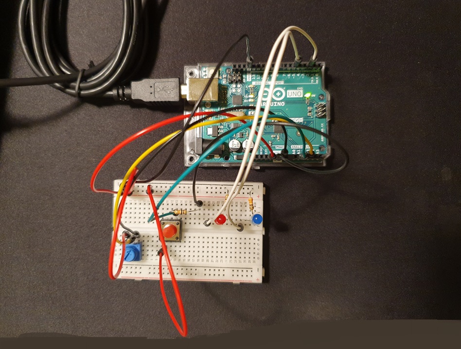
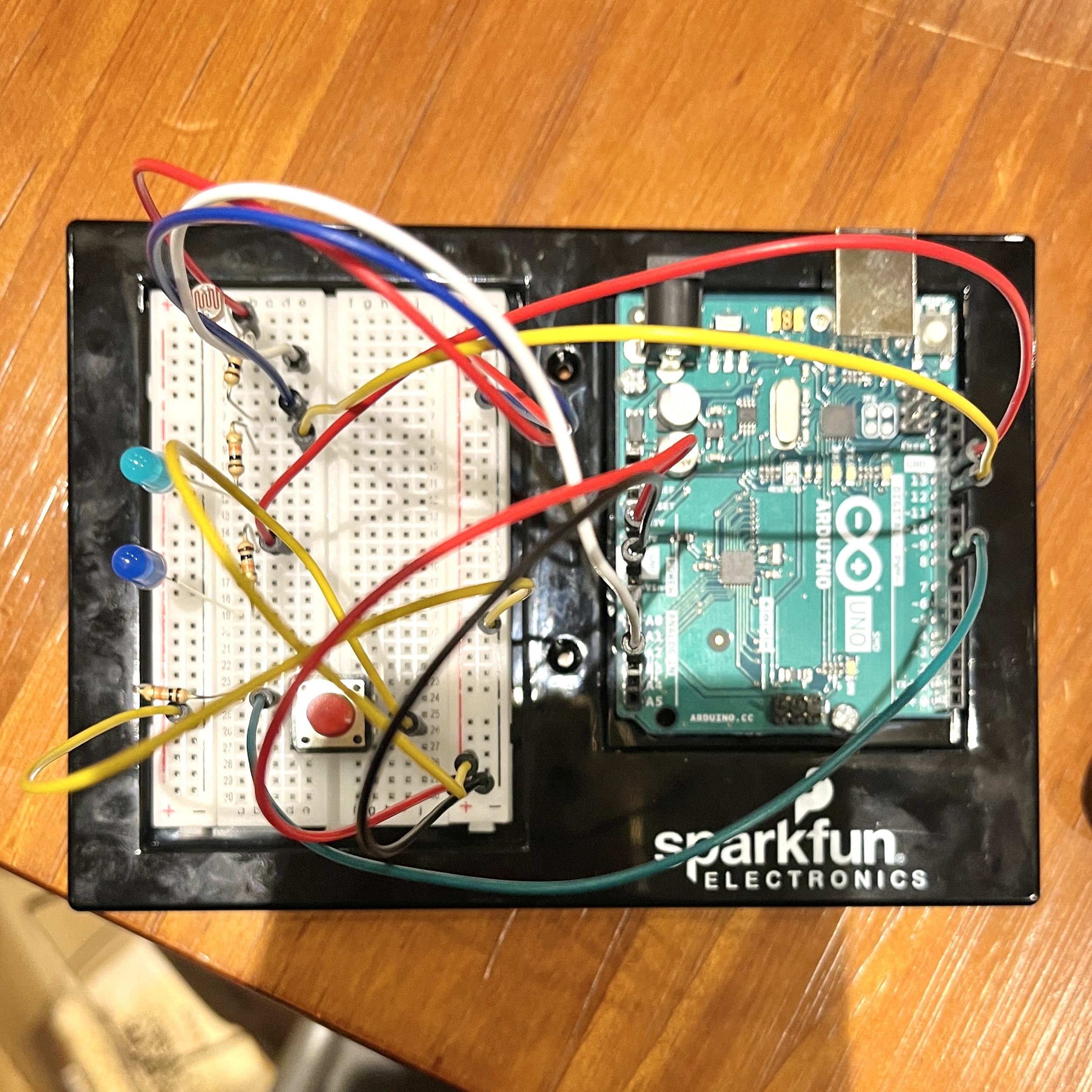
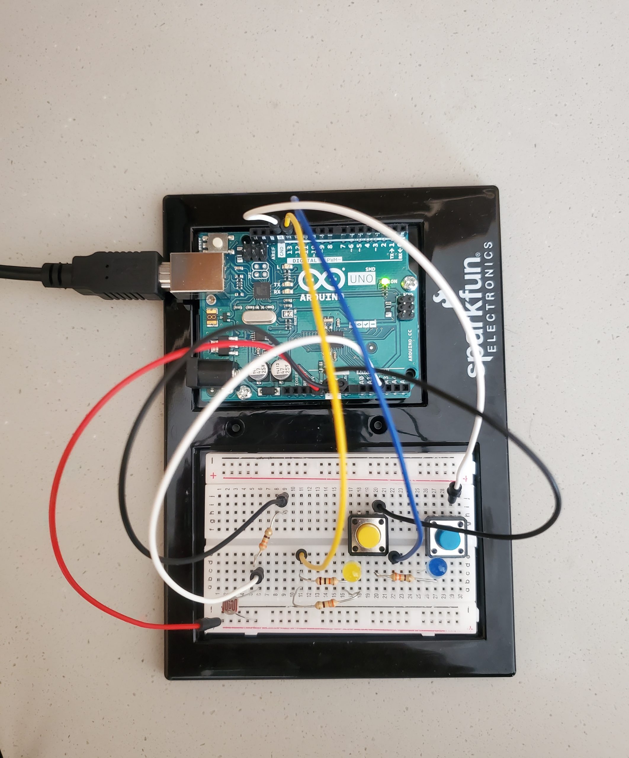
For this idea, I decided to develop a prototype of ambient light. The project makes use of a photoresistor that collects data from the ambiance and lights up an appropriate LED. Initially, I was planning on using a few other tools, in addition to the one already used, but the use of a photoresistor prevented the use of additional tools. Since the resistance of the circuit increases or decreases based on the lighting, adding a few other tools further increased the resistance in the total circuit, as a result, LEDs were not lighting up. Thus, I resorted to a simple design using two LEDs, four resistors (all 330 Ω), two switches, one photoresistor and a few lines of Arduino code. 

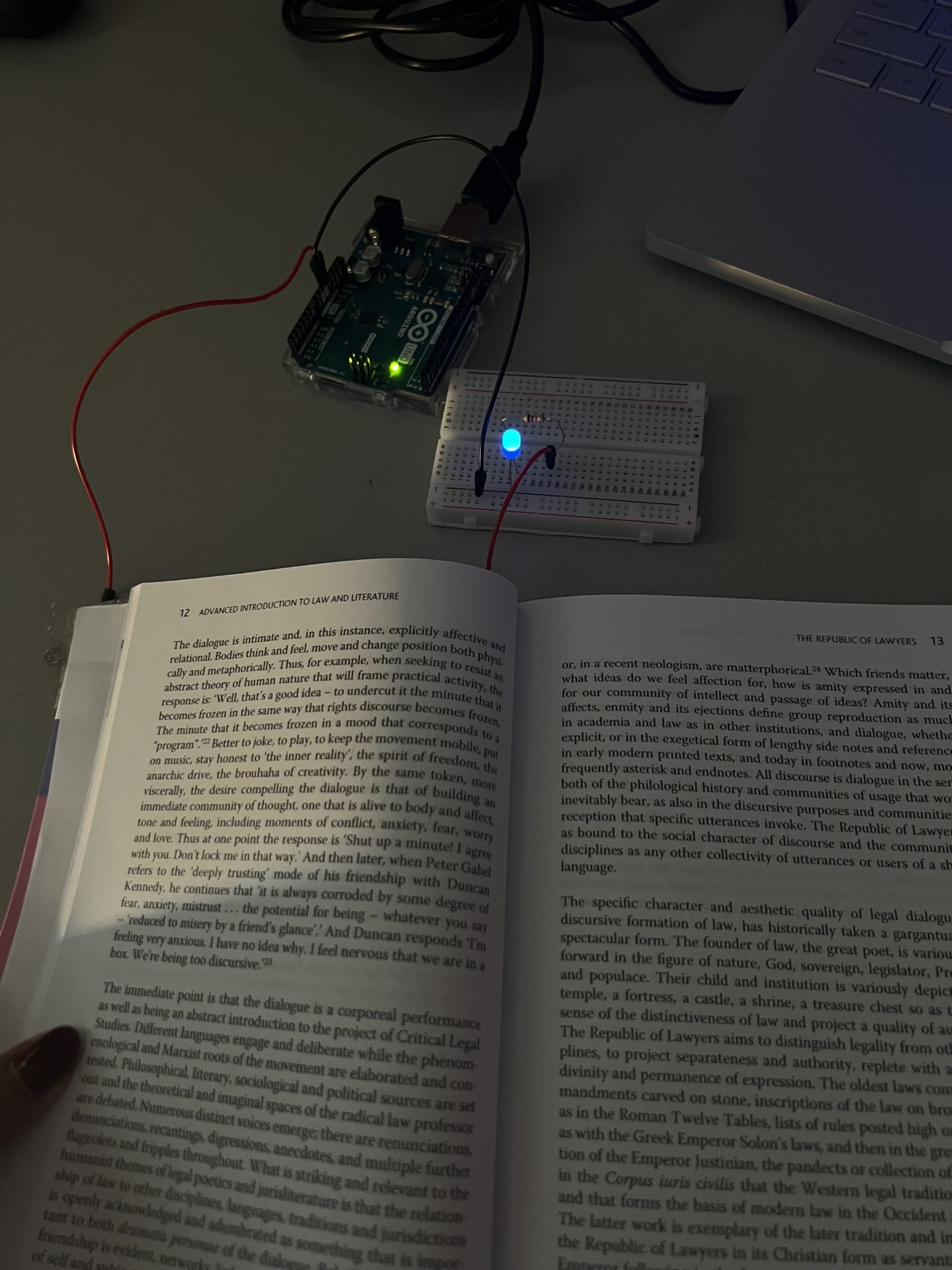
The idea of the project is straightforward in terms of functionality. The photoresistor detects the amount of light falling on the sensor, which then alters the resistance of the entire circuit. As a consequence of the altered resistance, the potential difference differs under varying conditions. Thus, if the potential difference falls under a particular threshold, one LED lights up and so on. 

Code

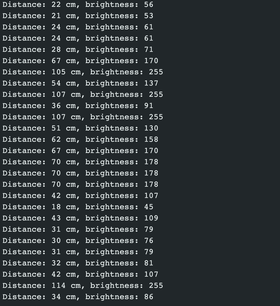
At the beginning of the program, different parameters of the project are controlled by a bunch of global variables declared at the very beginning of the file. Inside the loop() function, the readings from the photo sensor are stored in a variable called ‘volt_reading’ – the value is a range of (1-1023). However, to replicate the actual configuration, I converted this value to an equivalent volt. 

// Reading data from the photoresistor and storing it in volt_read
volt_read = analogRead(lightSensorPin);

// Mapping to a range of (0.0 V to 5.0 V)
float volt_converted = volt_read * (5.0/ 1023);

Here, the idea is similar to that of the map() function of p5.js. The value to be converted is mapped to a range of 1.0 V to 5.0 V since 5.0 V is the electromotive force (emf) of the circuit. This value is used in the latter section.

The LED controlling phase involves the use of conditional loops. The code that regulates which LED to light up is placed inside a function titled whichSensor() that takes the converted voltage reading as a parameter. The function is called recursively inside the loop() function. 

// Function that determines which LED to light up - takes converted volt reading as input
int whichSensor(int volt)
{
  int value_to_be_returned;

  if (volt >= 0 && volt < 1.8)
  {
    value_to_be_returned = 13;
  }
  else if (volt >= 1.5 && volt < 4.0)
  {
    value_to_be_returned = 12;
  }

  return value_to_be_returned;
}

Inside this function, two if-conditions run continuously and check the value stored in the argument — if the value is a range of [0, 1.8) V, digital pin “13” is used to light up a yellow LED; similarly, if the value is a range of [1.8, 5.0] V, digital pin “12” is used to light up the blue LED. 

View the entire project on GitHub.


Reflection 

The project involves the use of a photoresistor (an analog sensor). In order to make it more realistic, I added two switches to the circuit. Thus, if the yellow switch is pressed and the sensor is giving a certain reading, the yellow LED lights up and vice versa. 

Similarly, at first, the yellow LED was less fluorescent, so I added one 330 Ω resistor parallel to the already present resistor. This decreased the resistance of the circuit and the yellow LED was brighter. 

Overall, I am happy with the results. I wanted to include a total of three LEDs, but I could not because there are just ground terminals in the circuit — at present, all of them have been used. Moreover, my initial thought was to induce a flickering effect on the second LED when the first LED is emitting light, but the use of switches prevented this idea. Thus, one improvement could be to devise a mechanism that facilitates the implementation of the aforementioned idea. 

A partition has been placed between the LEDs and the photosensor for better visibility. Watch the completed demonstration on YouTube.


Analog & Digital

DESIGN

Because I am still unfamiliar with circuit building, what I created for this project is rather simple. Two elements on the board, a digital switch and a light sensor control two LED’s. When the program starts, the lights flicker in an alternating pattern with a starting interval of 500 milliseconds. However, the frequency at which the LED’s flicker is dependent on the light sensor: low levels of light cause the lights to flicker on a larger interval, and high levels of light cause the lights to flicker on a shorter interval. Finally, the switch changes the LED’s from flickering in an alternating pattern to a simultaneous pattern.

MATERIALS 

The materials I used for this project are listed below:

  • 2 LED’s
  • 3 10k Ohm resistors
  • wires
  • switch
  • light sensor

BUILDING THE CIRCUIT 

I began by building a simple 2 LED circuit like we had practiced in class. I then incorporated the switch, and finally I extended it to include the light sensor. A photo of the board is shown below:

CODE 

The most challenging part of this project was getting the button to toggle. In class, we had only worked with buttons that do something once when clicked; however, what I wanted was for the LED’s to maintain a certain pattern from the time the button was pressed to the time it was pressed again. To achieve this, I referenced the Arduino website. Ooutside of the setup() and loop() function, I define variables currentButtonState, previousButtonState, and ledState. The currentButtonState is obtained by reading the input at pin 8, which is where the switch on the board is connected. The ledState is initially set to LOW and is the variable that defines what the LED’s do. In the loop() function, the state of the button is defined by the following if statement:

if (previousButtonState == HIGH && currentButtonState == LOW) { 
  ledState = !ledState; 
  digitalRead(ledState); 
}

This statement essentially says that when the button is pressed, flip the ledState  from HIGH to LOW and vice versa. In separate if statements, I define the behavior of the LED’s, which has to options: flash simultaneously when the ledState is HIGH or flash alternating when the ledState is LOW. The code is shown below:

if (ledState) { 
  digitalWrite(LED1, LOW); 
  delay(interval); 
  digitalWrite(LED1, HIGH); 
  digitalWrite(LED2, HIGH); 
  delay(interval); 
  digitalWrite(LED2, LOW); 
}

if (!ledState) { 
  digitalWrite(LED1, HIGH); 
  delay(interval); 
  digitalWrite(LED1, LOW); 
  digitalWrite(LED2, HIGH); 
  delay(interval); 
  digitalWrite(LED2, LOW); 
}

FINAL PRODUCT

REFLECTIONS

As mentioned above, I find building circuits very challenging, while the coding portion comes more naturally to me. I am relatively comfortable coding in C, so making the transition to using C++ was not too difficult, and I actually had a lot of fun experimenting with the code. I do wish that this project could have been more creative and visually appealing, but I don’t think time allowed. I spent a lot of time taking apart the board and rebuilding the board several times so that I could better understand how the circuit was working.


Week 9: Analog & Digital

For this week’s assignment, I initially thought of doing a stoplight or a guessing game, but when I searched around on this website, I saw that many people have already done those concepts. I therefore decided to put a little spin on things by making a stoplight-esque guessing game. Since the potentiometer reminded me of a shower temperature dial, I made a temperature guessing game called “Swampy’s Shower”, where you help a little bathing crocodile get his desired water temperature.

I started out by assembling the basics: a blue, yellow, and red LED connected to three different pins, a digital switch to start and restart the game, and an analog potentiometer to serve as our shower dial. This was fairly straightforward, but it took so many wires. For the “interface” of the game, I used a piece of cardboard that I would slot into the breadboard to label the controls / signals. The one in the picture below is an initial version that I revised in order to also have instructions for the switch and knob.

No description available.

I had the greatest difficulty with making the digital switch because I plugged some things wrong, so I kept getting random values. Thankfully, Google and Youtube saved the day, and I got it working.

From there, writing the code was also fairly straightforward because I built my program off the Analog Switch program from class. I used a simple if else statement to compare the dial entry vs a randomly generated temperature. The switch, when pressed, starts the game. The game ends when the yellow pin flashes (when the temperature is just right!) and you can restart it again with the switch.

  if (sensorValue == randNumber) {
    Serial.println("JUST RIGHT");
    digitalWrite(yellowPin, HIGH); //just right
    digitalWrite(bluePin, LOW);
    digitalWrite(redPin, LOW);
    delay(2000);
    start = false;
  } else if (sensorValue > randNumber) {
    digitalWrite(yellowPin, LOW);
    digitalWrite(bluePin, LOW);
    digitalWrite(redPin, HIGH); //too hot
  } else if (sensorValue < randNumber) {
    digitalWrite(yellowPin, LOW);
    digitalWrite(bluePin, HIGH); //too cold
    digitalWrite(redPin, LOW);
  }

} else { //turn everything off
    digitalWrite(yellowPin, LOW);
    digitalWrite(bluePin, LOW);
    digitalWrite(redPin, LOW);
}

I tried having the LEDs flash (e.g. if the temperature is closer, the light would flash faster) but it was more distracting and annoying (and kind of made the game too easy too), so I decided to keep things simple and have the blue light be on if it was too cold and the red light be on if it was too hot. The only things I might improve would be more shower functionality (a way to turn water on? drain or fill the tub?) or maybe making the brightness of the bulb an indicator of the closeness of the answer.

No description available.

I’m very happy with my final product. Watch it here:


Assignment 5: Switch

Concept

For this assignment, I wanted to make my switch useful and involve it in something I do. I read and write a lot for my Political Science & Law and Society classes, so I chose to use a book to make my switch work. I borrowed some conductive fabric from the IM Lab, my Advanced Introduction to Law and Literature, and my Arduino kit, and got to work.

I decided that I wanted to use an LED light to light up the pages once the book is opened so that the reader is able to read in the dark. However, I obviously knew the LED light we have in our kits is too small, so when looking at the images and video below imagine a bigger and brighter light.

Implementation

Images

Video

Link (Video was too big to upload on post)

https://drive.google.com/file/d/1cYJXPSOgu55uT1rVhsz7reBrLLZ8t_bc/view?usp=sharing

Reflection

I found this assignment pretty fun to do besides the fact that it didn’t do what I wanted to do which was light up the pages. But, with a bigger and brighter light it would have worked out. For future improvements I’d have to find a way to take into consideration when the reader flips the pages or doesn’t have the book open all the way like it is needed for this switch to work.