For my final project, I am planning to create a sort of interactive game with the use of Arduino and p5js. The idea is to create a 3D controller, which would allow the user to play a game.
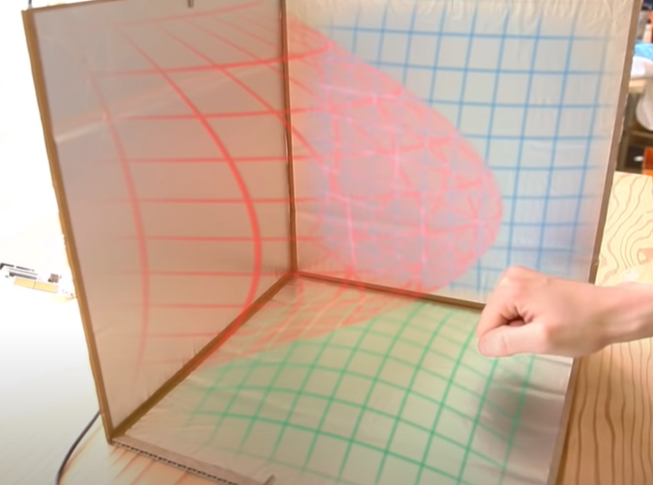
I got inspiration from watching this video → https://www.youtube.com/watch?v=ikD_3Vemkf0&feature=emb_title. In the video, the guy uses cardboard and foil, which can track the position of his hand. As he moves his hand, he can see the direction of the hand movement on the screen. So, I thought that I could connect Arduino to the cardboard with foil and make an interactive box, which sort of looks like this:
Turning to the screen, I thought to create a hidden object game. So there will be a picture presented on the screen with many objects and a gamer would need to find a red ball (for example) while moving their hand inside a cardboard box with a foil.
This idea also reminds me of a claw machine, so in any case, I have been thinking that I might use a joystick to find an object among many on the screen.
I know that the idea still seems “half-baked”, so I am looking forward to discussing how to improve it and implement it with the use of appropriate components.
When I was younger, I was OBSESSED with the Backyardigans. Maybe I still am a little 👀 . I watched it daily on Discovery Kids at 7:30pm before going to bed, and vividly remember there being one special two-part episode: Season 2 Episode 15: International Super Spy. (Yes this is the show and episode of that viral song.) I would pray for it to come on every night, and jump arround in joy when they did. For my final project for intro to IM, I am looking forward for constructing an interface similar to the one where Pablo has to dance to save Tasha from the lady in pink. (See Below or HERE if it does not work)
In this interface, Pablo stands on a pad and mimics a screen as it displays a character dancing. His movements are recorded and, if correct, marked in a progress bar. It indicates that he needs to complete the dance to earn a reward. I want to do something similar, where a displayed character can mimic or indicate specific dance moves from a person standing in front.
Idea ⌨️
For this concept, the display will be built with P5.Js, where a simple character, instructions and music will be shown. I would like to project this using one of the vertical projects. Furthermore, Arduino sensors will be used to record the position of the person. I imagine some pressure sensors in the floor to calculate where the user is standing (and with how many feet) , and a camera or infrared sensors to indicate the positions of key body parts (i.e hands, elbows, knees, toes, head). I would ask the person to get into a specific position, and record the difference in movement in a set period of time to determine if the movement is correct or not.
The feedback would mostly be similar to the one shown in the video, with a green progress bar that gets red and makes an error sound when a position is missed. I’d also like to include a reward system built with Arduino motors to give out a price for those of you who know how to dance.
I still want to develop this idea further, as I want to add elements to the design and concept that are mine. Yes, I want the vibe and situation of the Backyardigans, but I also want it to be signed Juanma. Perhaps adding more gimmicks or an extra step to the interface would be cool.
For my final project, I wanted to incorporate one of my hobbies, which is skating. I want to make a game where the player has to balance a character on a skateboard. The goal will be to obtain a high score while balancing the character. The pace of the game and balance will get more difficult as the player progresses.
The game will be made with p5js and the controls will be relayed from the Arduino. Currently, I am thinking of using touch sensors for input and motors for vibration feedback. I would like to discuss this further to see what would be the best components to use for input and if it is possible to include my penny board as a component.
This final project must incorporate both Arduino and p5js. I have a few ideas, here is one –
Idea: Game – Catch the Butterflies
{yes my butterfly obsession continues…}
The game would be made in p5js, which would have/be a butterfly garden. A catcher, which would be controlled using the Arduino (using a motion detecting sensor), would be used to catch butterflies and avoid unrelated/harmful items. The catcher would be the user’s hand, wherever the hand moves, the catcher will move the same direction. The more butterflies the user catches, the more points they get. If unrelated items are touched, a point will be deducted. It will be a timed game: How many butterflies can you catch in 1 minute? This is just a brief idea and there are many areas to think about, in terms of aesthetics, execution, etc.
Download the library here: TB6612FNG ARDUINO LIBRARY, or grab the latest version from Sparkfun’s GitHub repository. Once the library is installed, open the example code included in the Library through the Arduino IDE’s examples.
Transistor/diode
You would use the same set up with a diode and transistor for a solenoid as well.
When we started thinking about a potential instrument to make we thought of a piano, xylophone or a guitar. We began by experimenting with different analog sensors including pressure/force sensors and piezo elements. We settled on making a xylophone using 4 pressure sensors so that each time the sensor is pressed, the buzzer would make a sound and at the same time a LED would light up (synced with when the note is pressed). Syncing the LEDs with the sensors is what we struggled with the most, we had the wiring as well as the code however we could not get it to work.
First, we wired up the sensors & buzzer and wrote up the code to make each pressure sensor play a different note when pressed.
We then wired up a button (digital sensor) with 4 different LEDs. We did these two steps independently in order to make sure each one worked well on its own. However, what we found most challenging was to combine the two circuits and codes to make the whole thing work altogether. We wanted (1) the buzzer to play sound when the pressure sensor was hit, (2) the LED to light up when the pressure sensor was hit and be off otherwise and (3) the button to enable the ON and OFF of the LEDs adding a light feature to the xylophone.
#include "pitches.h"
#define FORCE_SENSOR_BLUE A0
#define FORCE_SENSOR_GREEN A1
#define FORCE_SENSOR_RED A2
#define FORCE_SENSOR_YELLOW A3

const int ledPinBlue = 7;
const int ledPinGreen = 2;
const int ledPinRed = 3;
const int ledPinYellow = 4;

const int buttonPin = 5;

bool onOff = HIGH;
byte prevButtonState = LOW;
bool blinking = false;

int notes [10] = {NOTE_C4, NOTE_D4, NOTE_E4, NOTE_F4, NOTE_G4, NOTE_A4, NOTE_B4, NOTE_C5, NOTE_D5, NOTE_E5};

void setup() {
  Serial.begin(9600);

//  pinMode(ledPinBlue, OUTPUT);
//  pinMode(ledPinGreen, OUTPUT);
//  pinMode(ledPinRed, OUTPUT);
  pinMode(ledPinYellow, OUTPUT);
  pinMode(buttonPin, INPUT);
}

void loop() {

  byte buttonState  = digitalRead(buttonPin);
  Serial.println(buttonState);

  if (buttonState == HIGH && prevButtonState == LOW) {

    blinking = !blinking;
  }

  prevButtonState = buttonState;

  int analogReadYellow = analogRead(FORCE_SENSOR_YELLOW);
  int analogReadRed = analogRead(FORCE_SENSOR_RED);
  int analogReadGreen = analogRead(FORCE_SENSOR_GREEN);
  int analogReadBlue = analogRead(FORCE_SENSOR_BLUE);

  Serial.print(analogReadYellow);
  Serial.print(analogReadRed);
  Serial.print(analogReadGreen);
  Serial.print(analogReadBlue);// print the raw analog reading

  if (analogReadYellow > 100) {
    Serial.println(" --> YELLOW ");
    tone (6, NOTE_C4, 200);
  }
  if (blinking == true){
    digitalWrite(ledPinYellow, HIGH);
    }
   else {
    digitalWrite(ledPinYellow, LOW);
    }

  if (analogReadRed > 200) {
    Serial.println(" --> RED ");
    tone (6, NOTE_D4, 200);
    pinMode(ledPinRed, HIGH);
    }
   else {
    digitalWrite(ledPinRed, LOW);
    }

  if (analogReadGreen > 200) {
    Serial.println(" --> GREEN ");
    tone (6, NOTE_E4, 200);
    pinMode(ledPinGreen, HIGH);
    }
   else {
    digitalWrite(ledPinGreen, LOW);
    }

  if (analogReadBlue > 200) {
    Serial.println(" --> BLUE ");
    tone (6, NOTE_F4, 200);
    pinMode(ledPinBlue, HIGH);
    }
   else {
    digitalWrite(ledPinBlue, LOW);
    }
}
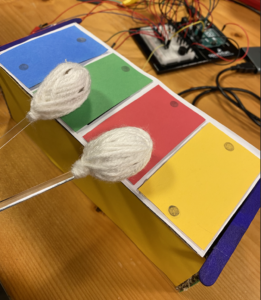
We then spent time working on the aesthetics of the instrument. Using cardboard and paper we created the xylophone with a box underneath (where we planned to hide all the wires and breadboard). We made two mallets and had to make them heavy enough so that the sensors could detect the pressure. We also realized that by using the proper resistor (10k) the sensor was more sensitive and did not require for the mallet to be used with much force. Switching the sensors and the wires over to the cardboard box was very difficult as there are a lot of wires, but, what worked was checking the wiring for each sensor by attaching a spare sensor before attaching the wires to the sensor in the box, this was a quick and easy way to make sure it was working properly, before make it so that you can’t see where the wires are and if they’re touch.
For this assignment, using both analog and digital sensors, we were tasked to create a musical instrument. At first, we thought of creating a drum set. After doing some research we realized that we will have to connect a MIDI tool and use that as an interface in order to make a drum that mimics the actual sounds that come from a drum. Since we had already covered some notes in class (pitches), we decided to make a Piano instead but using the same methods we would use to make the drums.
Implementation
We started by researching all our possible analog sensors. We think the sensor best-suited for this task is a piezoelectric pressure sensor because we wanted to measure the force with which the user presses down on each key.
Next, we wanted to design our piano. For this, we used a cardboard box from the lab which had a piece of cardboard that could be flipped up and down. This flipping part would serve as the piano keys and the rest of the box can be used to hide the Arduino and the circuits. Piezo sensors are stuck underneath each key using double-sided tape. We also soldered wires together to make the circuit compact enough to fit inside the cardboard box and so that the wires may be led to the Arduino through holes in the box. Finally, we used a potentiometer to adjust for the volume of the buzzer.
Initial setup (testing)
Reflection
While we have made a piano that can play 6 notes, it’s biggest drawback is in how limited it is. We believe that this problem can be solved by either having a button (switch) that changes all the notes being played so that every key is now bound to a new note when the button is pressed or by achieving the same thing using a potentiometer.
We ran into a problem at the end. The last piezo sensor does not seem to work. We spent most of our time trying to figure out what’s wrong with our code that triggers the last sensor every time in draw loop. But, in the end, we figured that the sensor was faulty. Since we did not have enough time to fix this and use another sensor (we had already soldered the faulty one), we did not include that sensor in the piano.
Here is how the final setup looked. Of course, this was not how we imagined it to be, but it was the right thing to do since we didn’t want to break the connections and have the wires come loose. Even after all the soldering we did, there were few wires that did not connect properly to the alligator cables and thus the piezo disk would play any sound.
Arduino Code
#include "pitches.h"

int analogpin[6] = {A0, A1, A2, A3, A4, A5};
const int buzpin = 4;
int threshold = 200;
int flag = 0;
bool a5 = false;

double curr;
double goal;

void setup()
{
  Serial.begin(9600);
  pinMode(buzpin, OUTPUT);
}

void loop()
{
//  int test = analogRead(analogpin[4]);
//  Serial.println(test);

  if (analogRead(analogpin[0]) < threshold && flag == 0) //&& flag == 0
  {
    flag = 1;
    Serial.println("A0");
    curr = millis();
    while(millis() < curr + 100){
      tone(buzpin, NOTE_B4, 100); //need the duration here?
    }
  }

  if (analogRead(analogpin[1]) < threshold && flag == 0) //&& flag == 0
  {
    flag = 1;
    Serial.println("A1, pressing");
    digitalWrite(buzpin, HIGH);
    curr = millis();
    while(millis() < curr + 100){
      tone(buzpin, NOTE_D4, 100); //need the duration here?
    }
  }

  if (analogRead(analogpin[2]) < threshold && flag == 0) //&& flag == 0
  {
    flag = 1;
    Serial.println("A2");
    curr = millis();
    while(millis() < curr + 100){
      tone(buzpin, NOTE_C4, 100); //need the duration here?
    }
  }

  if (analogRead(analogpin[3]) < threshold && flag == 0) //&& flag == 0
  {
    flag = 1;
    Serial.println("A3");
    curr = millis();
    while(millis() < curr + 100){
      tone(buzpin, NOTE_G4, 100); //need the duration here?
    }
  }


  if (analogRead(analogpin[4]) < threshold && flag == 0) //&& flag == 0
  {
    flag = 1;
    Serial.println("A4");
    curr = millis();
    while(millis() < curr + 100){
      tone(buzpin, NOTE_G3, 100); //need the duration here?
    }
  }

  if (analogRead(analogpin[5]) < threshold && flag == 0 && a5 == false) //
  {
    flag = 1;
    a5 = true;
    Serial.println("A5");
    curr = millis();
    while(millis() < curr + 100){
      tone(buzpin, NOTE_D3, 100); //need the duration here?
      a5 = false;
    }
  }

  flag = 0;
}
Ideation
In this week’s assignment we are expected to create a Musical Instrument. Initially we planned to create a Marble Shaker- using the Servo to shake a box of marble from both sides. That was not quite successful because either the box would move completely or not move at all. We were fixated on using the servo and it just clicked about hit sticks on a box using the servo.
Final Product
We used the Ultrasonic sensor to change the speed of the Servo i.e. the hands of the Slap-O-Meter. The closer an object gets to the sensor, the faster the hands moves. The hands are adjusted at an angle to the box so regardless of the speed, it hits the box properly. Here is the code that we used to control the servo and the ultrasonic sensor:
Reflection
We had a lot of fun implementing it! No major challenges apart from some software issues on my laptop and so we just ended up connecting both Arduino to Hind’s laptop.
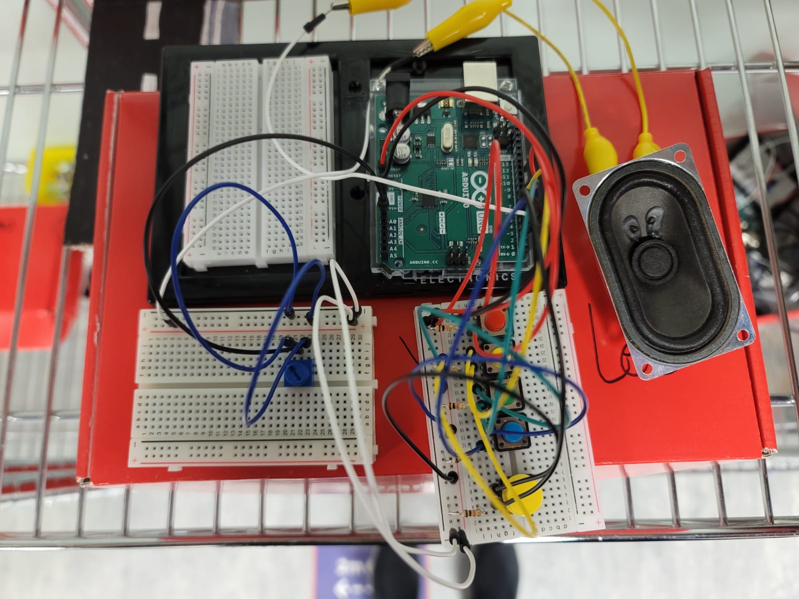
We made a very simple toy electric guitar that anyone can use and make music with just by pressing the buttons in the right order. The tempo of the notes can also be changed using the potentiometer, which challenges the user by seeing how quick they can play the guitar.
Initially, we wanted to use the potentiometer to change the volume of the speakers and we managed to use the potentiometer as a variable resistor almost to change how much current went into the speaker, but the speakers only got soft in the middle range of the potentiometer and got louder at the two extremes, which is unsuitable to use as a switch. Because of this we decided to use it to change the tempo of the notes instead.
Below is an image of the circuit.
Here is the code and video:
#include "sound.h"

int counter = 0;
int group = 0;
int playMode = 0;

byte But1, PBut1, But2, PBut2, But3, PBut3, But4, PBut4, But5, PBut5;

bool lastnote = false;

int But1Note [] = {NOTE_A2, NOTE_B2, NOTE_C3, NOTE_D3, NOTE_E3, NOTE_F3, NOTE_A3, NOTE_B3, NOTE_C4};
int But2Note [] = {NOTE_B2, NOTE_C3, NOTE_D3, NOTE_E3, NOTE_F3, NOTE_G3, NOTE_D4, NOTE_C4, NOTE_B3};
int But3Note [] = {NOTE_C3, NOTE_D3, NOTE_E3, NOTE_F3, NOTE_G3, NOTE_A3};

int ending [] = {NOTE_A5, NOTE_G5, NOTE_F5, NOTE_E5, NOTE_D5, NOTE_C5, NOTE_B4, NOTE_A4, NOTE_G4, NOTE_E5, NOTE_D5, NOTE_C5, NOTE_B4, NOTE_A4, NOTE_G4, NOTE_F4, NOTE_E4, NOTE_D4, NOTE_C4, NOTE_B3, NOTE_A3};

int play[3];

int octave = 0;

int toneNum;
unsigned long timer = 0;
unsigned long timer2 = 0;

void setup() {
  pinMode(2, INPUT);
  pinMode(3, OUTPUT);
  pinMode(4, INPUT);
  pinMode(5, INPUT);
  pinMode(6, INPUT);
  pinMode(7, INPUT);

  Serial.begin(9600);
}

void loop() {

  if (millis() > timer2) {
    // 3 Buttons that plays 3 notes of the guitar solo
    But1 = digitalRead(7);
    if (But1 == HIGH && PBut1 == LOW) {
      counter = 0;
      for (int i=0; i<3; i++){
        play[i] = But1Note[i+3*group];
      }
    }
    PBut1 = But1;

    But2 = digitalRead(6);
    if (But2 == HIGH && PBut2 == LOW) {
      counter = 0;
      for (int i=0; i<3; i++){
        play[i] = But2Note[i+3*group];
      }
    }
    PBut2 = But2;

    But3 = digitalRead(5);
    if (But3 == HIGH && PBut3 == LOW) {
      if (group == 2) {}
      else{
        counter = 0;
        for (int i=0; i<3; i++){
        play[i] = But3Note[i+3*group];
        }
      }
    }
    PBut3 = But3;

    // this button switches the notes to the next group of the solo
    But4 = digitalRead(4);
    if (But4 == HIGH && PBut4 == LOW) {
      if (group<2){
        group++;
      }
      else group = 0;
    }
    PBut4 = But4;

    // this button switches to the next octave
    But5 = digitalRead(2);
    if (But5 == HIGH && PBut5 == LOW) {
        group = 0;
      if (octave<2){
        octave++;
      }
      else if (octave == 2) {octave++; counter =300;}
      else {octave = 0;}
    }
    PBut5 = But5;

    timer2 = millis() + 10;
  }

  // input from Pot.
  long potVal = analogRead(A0);
  long mapVal = map(potVal, 0, 1023, 100, 350);

  // sound player
  if (millis() > timer) {

    if (counter > 2 && octave !=3) {noTone(3);}
    else if (octave == 3 && counter<21) {tone(3, ending[counter], mapVal+50);}
    else if (octave == 3 && counter>=21) {noTone(3);}
    else{
      tone(3, play[counter]*pow(2,octave), mapVal+50);
    }

    counter++;
    timer = millis() + mapVal;
  }
}
Wouldn’t it be really cool if we built an instrument that made us feel like a DJ? Gathering inspiration from the current use of DJ Consoles and launchpads in the live music industry, we decided on constructing an instrument focused on rhythm and remixing of sounds. We wanted a nice-looking interface that would allow us to modify specific values of sound, and trigger desired notes/mp3’s. But how did we want it to sound?
Have any of you ever asked Siri to beatbox? We had, and so had the internet. From this response from our voice assistant, through which we reference this week’s class discussions, we gave the instrument a name and an initial set of sounds. However, by tapping into the options available by Serial Communication between the P5.js and Arduino, we realized the potential versatility of our instrument. Our instrument did not need to have a specific set of sounds!
Product:
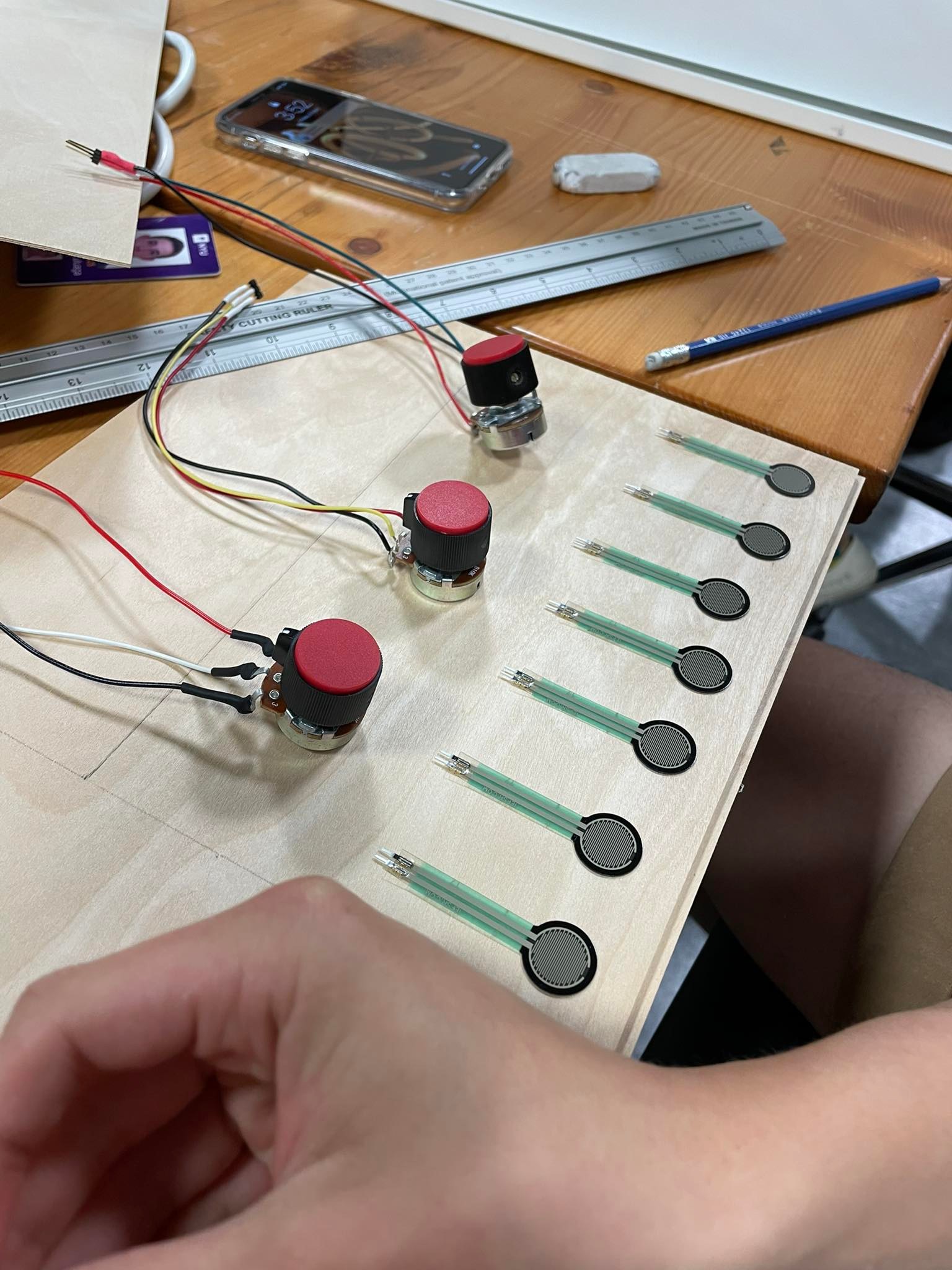
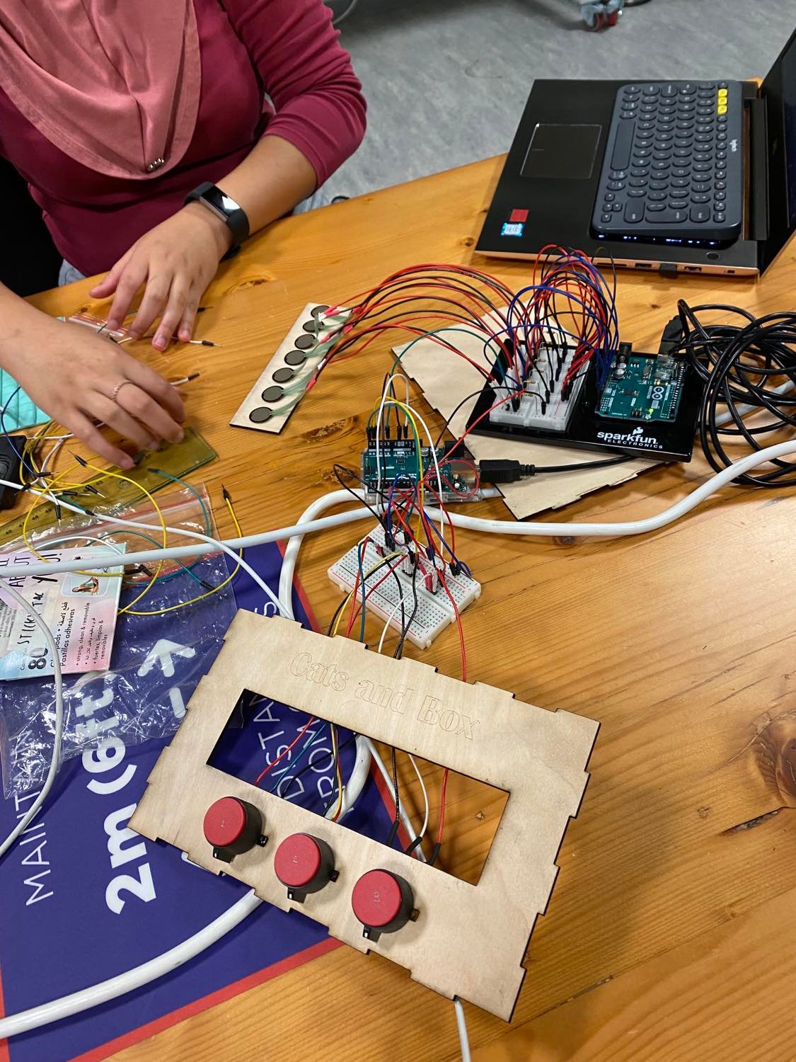
As preparation for the final project, and further Interactive Media endeavors, we wanted to explore the resources available to us in the Interactive Media lab by creating a neat interface and the serial connection. Thus, we built a wooden box with laser-cut sheets that would hold the cables inside/behind. This box has 3 potentiometers, which we soldered that control the volume of 3 different looping sounds. The first one from the left also controls the color of an RGB LED light (which you toggle on/Off with a button) to allow for a more immersive DJ experience. It also has a board with 7 pressure sensors that play a specific sound each.
With the way our code works, you are able to easily upload any .mp3 file to replace the current ones, and thus, completely change the sound of Cats and Box. This makes it similar to a launchpad in that you can completely customize the sounds you input.
Because we had 10 Analog inputs, we had to use two Arduinos, and write two different sets of code. Nevertheless, the premise is the same: We Serial.print a string of the values of each sensor in the arduino. This string is received by P5.js, assigning each value to a specific output. In P5.js we use if statements and variables to control the sounds and volumes.
Here are our codes:
Arduino – Juan’s Laptop
void setup() {
  Serial.begin(9600);
}
void loop() {
  int oneValue = analogRead(A0);

  int twoValue = analogRead(A1);

  int threeValue = analogRead(A2);

  int fourValue = analogRead(A3);

  int fiveValue = analogRead(A4);

  int sixValue = analogRead(A5);


    int sensorValue = oneValue;
    Serial.print(sensorValue);
    Serial.print(",");
    sensorValue = twoValue;
    Serial.print(sensorValue);
    Serial.print(",");
    sensorValue = threeValue;
    Serial.print(sensorValue);
    Serial.print(",");
    sensorValue = fourValue;
    Serial.print(sensorValue);
    Serial.print(",");
    sensorValue = fiveValue;
    Serial.print(sensorValue);
    Serial.print(",");
    sensorValue = sixValue;
    Serial.print(sensorValue);
    Serial.println();
    delay(1);
  }
P5.Js – Juan’s Laptop
Arduino – Lily’s Laptop
const int redPin= 9;
const int greenPin = 10;
const int bluePin = 11;

const int buttonPin = 2;
byte prevButtonState = LOW;
int currentButtonState;

unsigned long timer = 0;
bool blinking = false;
bool onOff = LOW;

const int colour_number = 7;
int ledState = LOW;

void setup() {
  Serial.begin(9600);
  pinMode(redPin, OUTPUT);
  pinMode(greenPin, OUTPUT);
  pinMode(bluePin, OUTPUT);
  currentButtonState = digitalRead(buttonPin);
}

void loop() {
int potValue1 = analogRead(A3);
int colourChoice = potValue1 / (1024 / colour_number);

//for checking if circuit is on or off
  byte currentButtonState = digitalRead(buttonPin);


  if(currentButtonState == HIGH && prevButtonState == LOW) {

    // toggle state of LED
    ledState = !ledState;

    // control LED arccoding to the toggled state

  if (colourChoice > colour_number - 1) {
    colourChoice = colour_number - 1;
  }

  else if (colourChoice == 0) {
    SetColor(18, 221, 54);
  }
  else if (colourChoice == 1) {
    SetColor(235, 242, 39);
  }
  else if (colourChoice == 2) {
    SetColor(234, 31, 37);
  }
  else if (colourChoice == 3) {
    SetColor(0, 255, 0);
  }
  else if (colourChoice == 4) {
    SetColor(249, 88, 212);
  }
  else if (colourChoice == 5) {
    SetColor(29, 33, 168);
  }
  else if (colourChoice == 6) {
    SetColor(0, 193, 249);
  }
  } else {
    digitalWrite(redPin, LOW);
    digitalWrite(greenPin, LOW);
    digitalWrite(bluePin, LOW);
    }
 // Serial.println(potValue1);
 // read the incoming byte - always read whether you need that info or not
   int inByte = Serial.read();

   int sensorValue = analogRead(A0);
    Serial.print(sensorValue);
    Serial.print(",");
    sensorValue = analogRead(A1);
    Serial.print(sensorValue);
    Serial.print(",");
    sensorValue = analogRead(A2);
    Serial.print(sensorValue);
    Serial.print(",");
    sensorValue = analogRead(A3);
    Serial.print(sensorValue);
    Serial.println();
    delay(300);
  }

void SetColor(int R, int G, int B) {
  analogWrite(redPin,   R);
  analogWrite(greenPin, G);
  analogWrite(bluePin,  B);
}
P5.Js – Lily’s Laptop
Process:
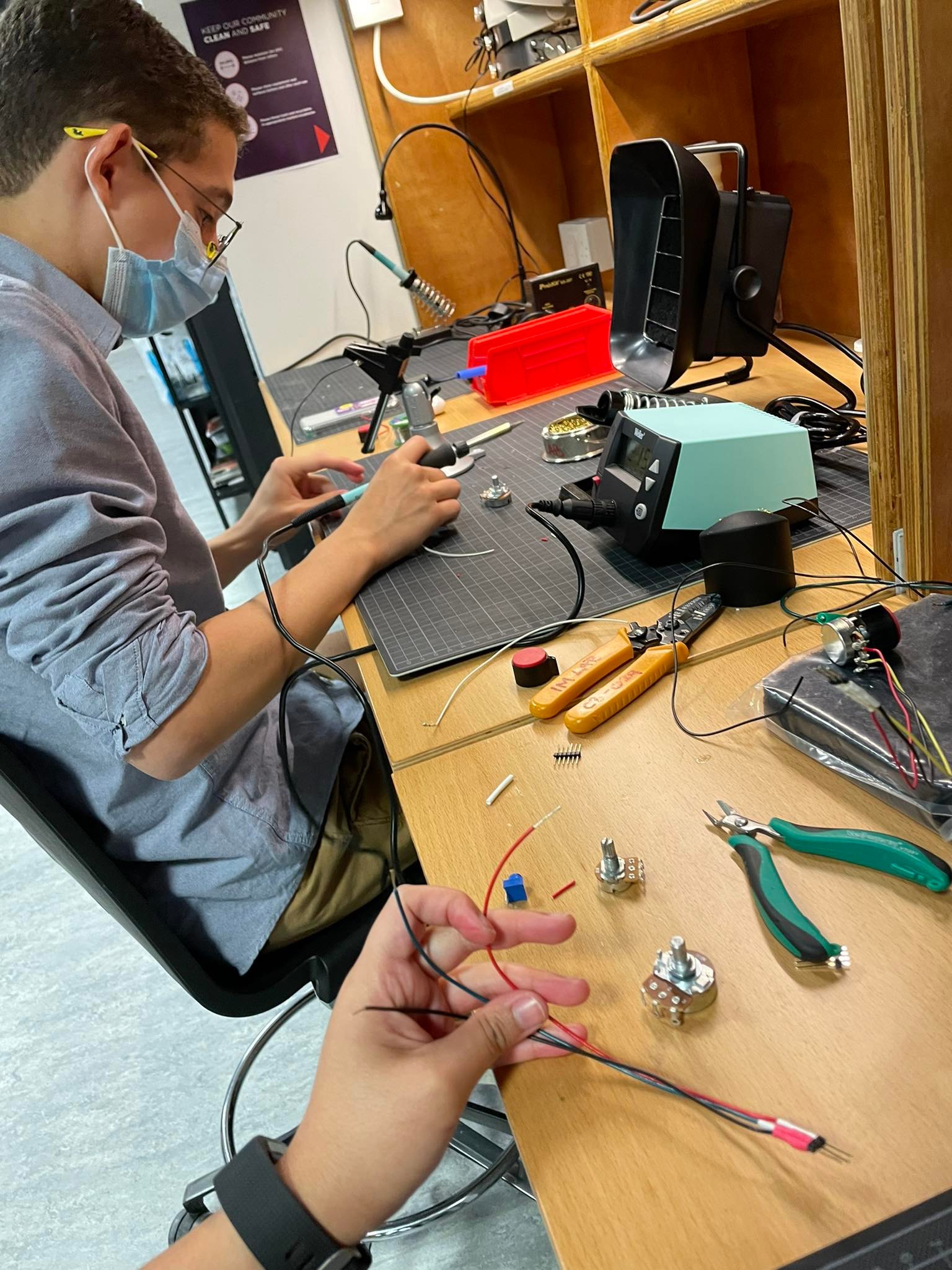
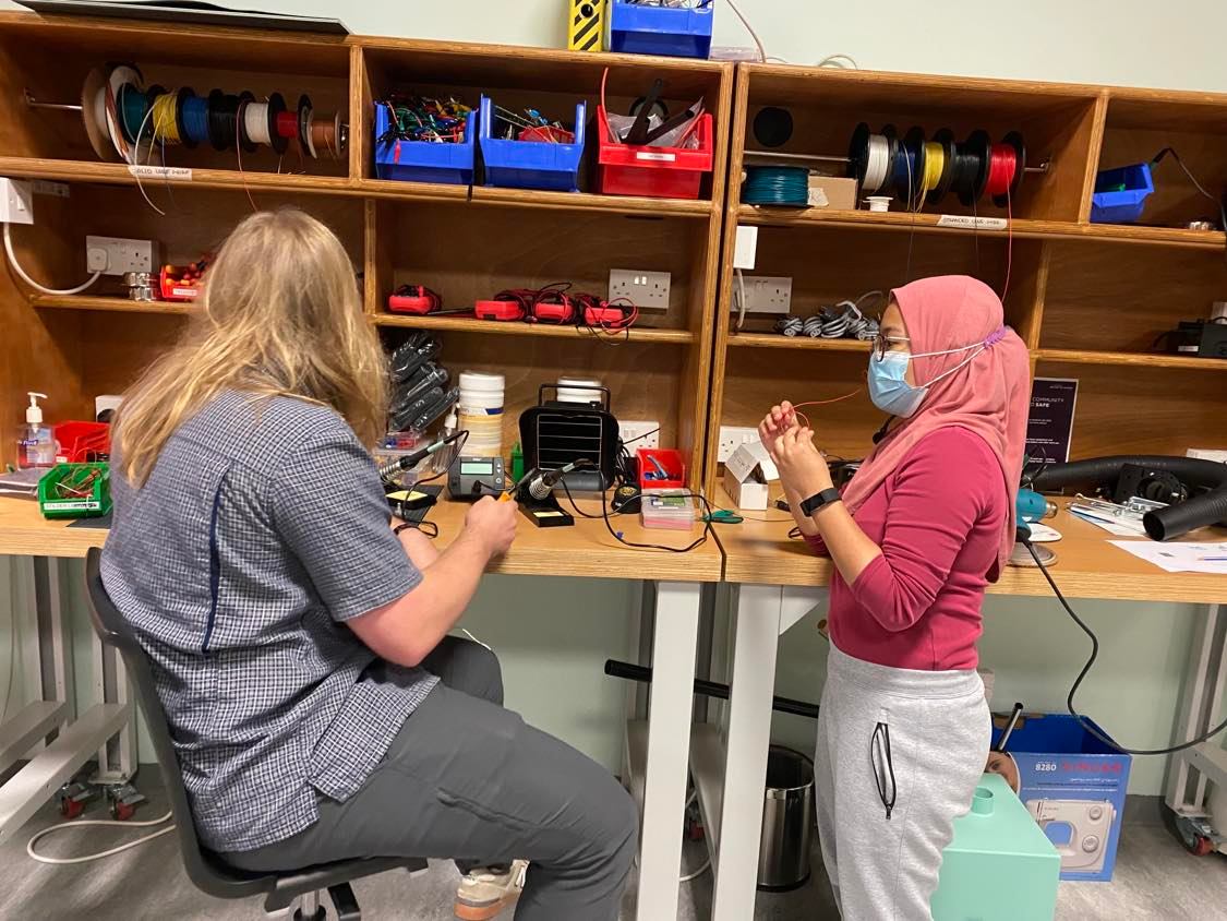
As previously mentioned, we needed to learn and study a lot to build Cats and Box. The first step was learning how to solder. During last week, Kyle Adams and other IM lab assistants were explaining the process to us, guiding us through safety procedures, and helping us with the brainstorming. Kyle, Zion and Alima dedicated a lot of time to guide us through the laser cutting for the box. Without them, we would be very very lost. Once we figured out our interface, building the code with the Serial connection was a big challenge. We struggled to understand the “handshake” and had to watch a few tutorials and read many, many articles to properly manipulate and update the code. Nick and Shamma were an incredible support for us. After many hours of work, we got everything functioning. And then, it was only a matter of assembly and fine-tuning.
Some pictures –
Here is our Final Product:
Reflection:
Juanma: I am very very proud of how our instrument looks. It is the product of countless hours spent in the IM lab and a representation of our steep learning curve. We decided to include many elements that were optional/outside of our scope in order to strengthen our toolbox, and I am very happy we did. In the future, I would like for the sounds to be a bit more seamless, to figure out a way to trigger them multiple times in a row without having to wait for it to end or creating noise, and to include a laser cut space for the LED and cables. However, these are the things that we will keep in mind in future projects and that don’t take away from the awesomeness of Cats and Box. Furthermore, I am very grateful for all the IM students and staff that were more than eager to teach us and help us reach our goal.
Lily: This assignment felt more like a final project than it does a weekly assignment – it took us several late nights to get the p5.js code functioning alongside the arduino. The arduino code was straightforward and it was fun to figure out how to work the RGB lights and button in line with that. However, more work definitely needs to be done to understand integrating sound through p5.js and arduino. Overall I’m very happy with what we came up with and working with Juan was seamless – he was good at things that I’m not good at and vice versa. I’m also very very thankful for Kyle and other IM lab assistants who were very happy to teach us new things like soldering, which truly is what made the mechanics of our instrument work.

 Turning to the screen, I thought to create a hidden object game. So there will be a picture presented on the screen with many objects and a gamer would need to find a red ball (for example) while moving their hand inside a cardboard box with a foil.
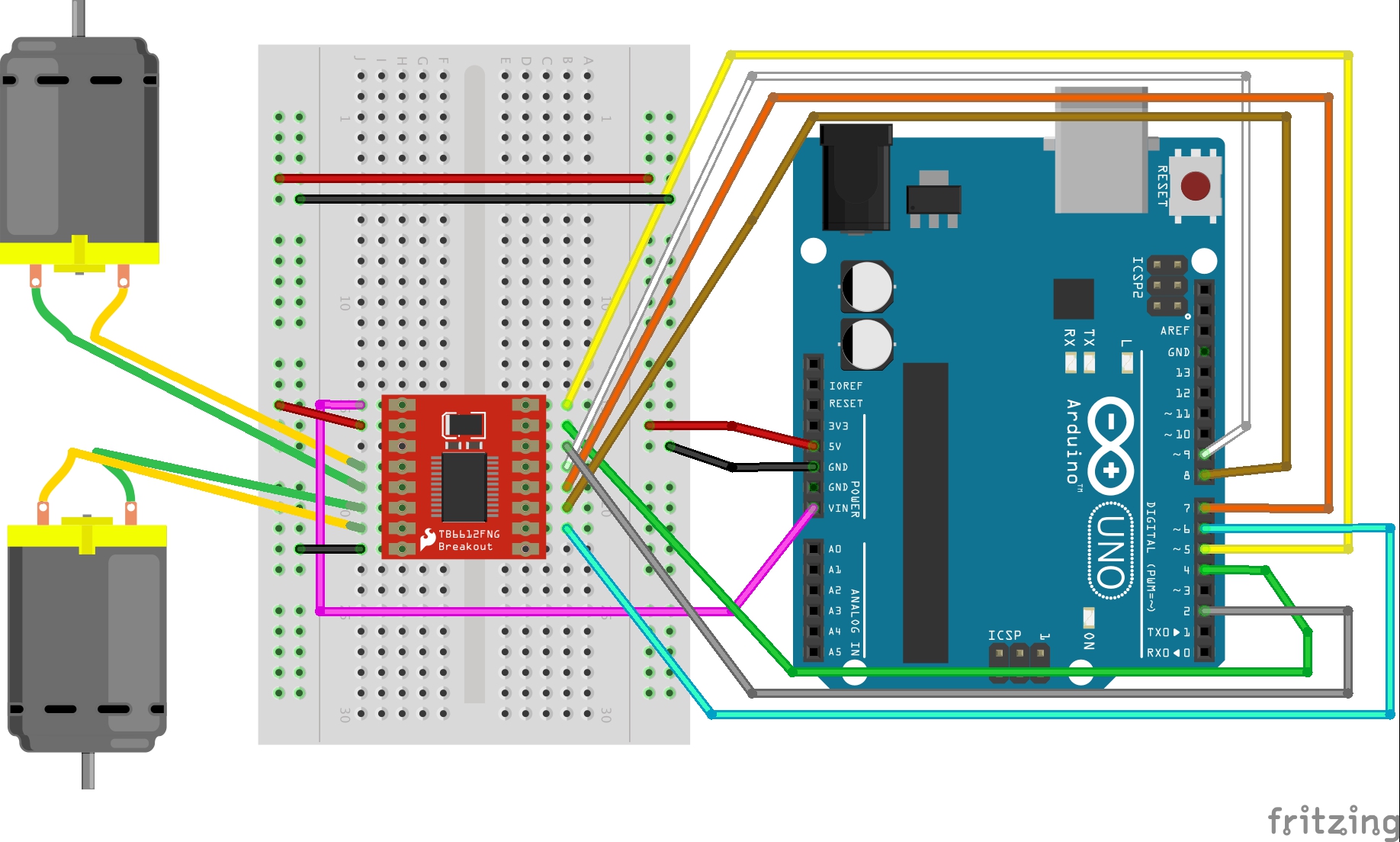
 When we started thinking about a potential instrument to make we thought of a piano, xylophone or a guitar. We began by experimenting with different analog sensors including pressure/force sensors and piezo elements. We settled on making a xylophone using 4 pressure sensors so that each time the sensor is pressed, the buzzer would make a sound and at the same time a LED would light up (synced with when the note is pressed). Syncing the LEDs with the sensors is what we struggled with the most, we had the wiring as well as the code however we could not get it to work.