pitches.h:
/*************************************************

 * Public Constants

 *************************************************/

#define NOTE_B0  31
#define NOTE_C1  33
#define NOTE_CS1 35
#define NOTE_D1  37
#define NOTE_DS1 39
#define NOTE_E1  41
#define NOTE_F1  44
#define NOTE_FS1 46
#define NOTE_G1  49
#define NOTE_GS1 52
#define NOTE_A1  55
#define NOTE_AS1 58
#define NOTE_B1  62
#define NOTE_C2  65
#define NOTE_CS2 69
#define NOTE_D2  73
#define NOTE_DS2 78
#define NOTE_E2  82
#define NOTE_F2  87
#define NOTE_FS2 93
#define NOTE_G2  98
#define NOTE_GS2 104
#define NOTE_A2  110
#define NOTE_AS2 117
#define NOTE_B2  123
#define NOTE_C3  131
#define NOTE_CS3 139
#define NOTE_D3  147
#define NOTE_DS3 156
#define NOTE_E3  165
#define NOTE_F3  175
#define NOTE_FS3 185
#define NOTE_G3  196
#define NOTE_GS3 208
#define NOTE_A3  220
#define NOTE_AS3 233
#define NOTE_B3  247
#define NOTE_C4  262
#define NOTE_CS4 277
#define NOTE_D4  294
#define NOTE_DS4 311
#define NOTE_E4  330
#define NOTE_F4  349
#define NOTE_FS4 370
#define NOTE_G4  392
#define NOTE_GS4 415
#define NOTE_A4  440
#define NOTE_AS4 466
#define NOTE_B4  494
#define NOTE_C5  523
#define NOTE_CS5 554
#define NOTE_D5  587
#define NOTE_DS5 622
#define NOTE_E5  659
#define NOTE_F5  698
#define NOTE_FS5 740
#define NOTE_G5  784
#define NOTE_GS5 831
#define NOTE_A5  880
#define NOTE_AS5 932
#define NOTE_B5  988
#define NOTE_C6  1047
#define NOTE_CS6 1109
#define NOTE_D6  1175
#define NOTE_DS6 1245
#define NOTE_E6  1319
#define NOTE_F6  1397
#define NOTE_FS6 1480
#define NOTE_G6  1568
#define NOTE_GS6 1661
#define NOTE_A6  1760
#define NOTE_AS6 1865
#define NOTE_B6  1976
#define NOTE_C7  2093
#define NOTE_CS7 2217
#define NOTE_D7  2349
#define NOTE_DS7 2489
#define NOTE_E7  2637
#define NOTE_F7  2794
#define NOTE_FS7 2960
#define NOTE_G7  3136
#define NOTE_GS7 3322
#define NOTE_A7  3520
#define NOTE_AS7 3729
#define NOTE_B7  3951
#define NOTE_C8  4186
#define NOTE_CS8 4435
#define NOTE_D8  4699
#define NOTE_DS8 4978
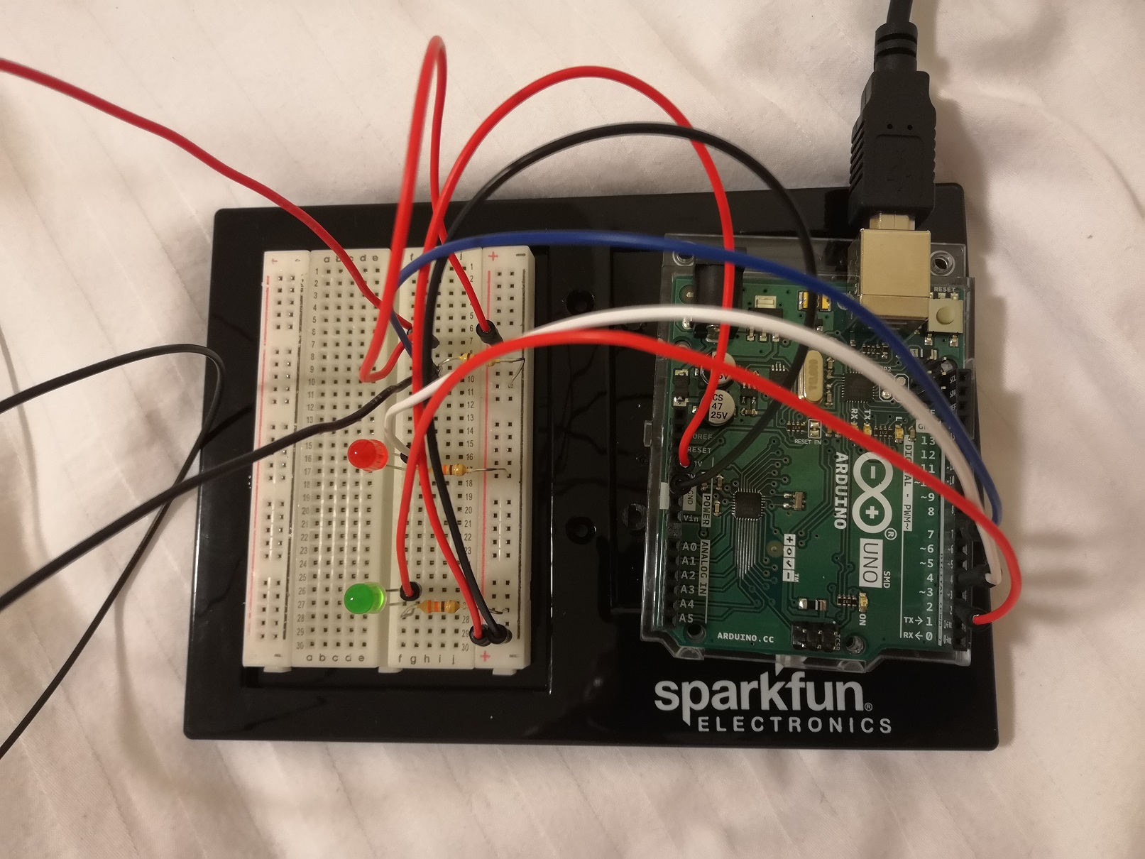
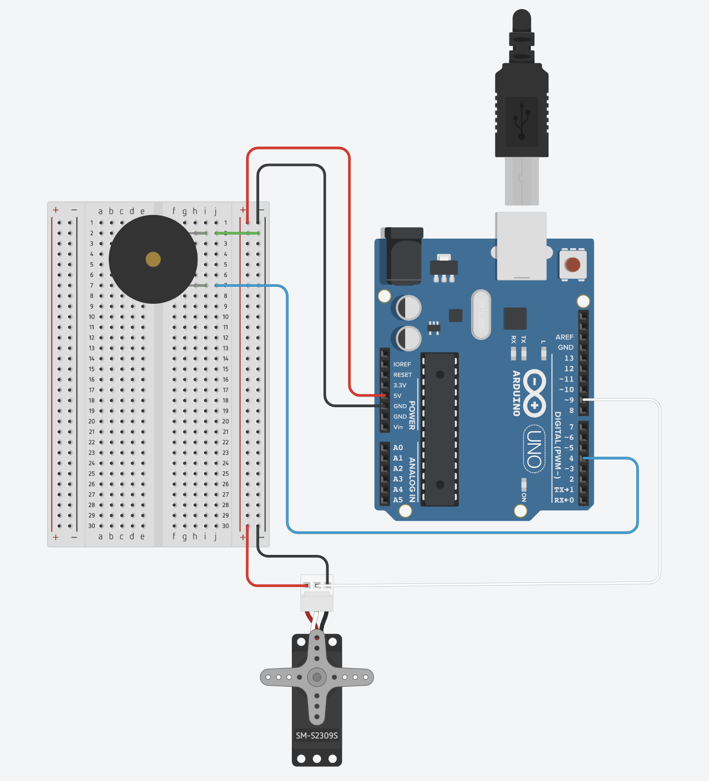
#include <Servo.h>
#include "pitches.h"
Servo servo;
int servoPos = 100;
int whichNote = 0;
int notes[10] = {NOTE_C4, NOTE_D4, NOTE_E4, NOTE_F4, NOTE_G4, NOTE_A4, NOTE_B4, NOTE_C5, NOTE_D5, NOTE_E5};
int durations[10];
void setup() {
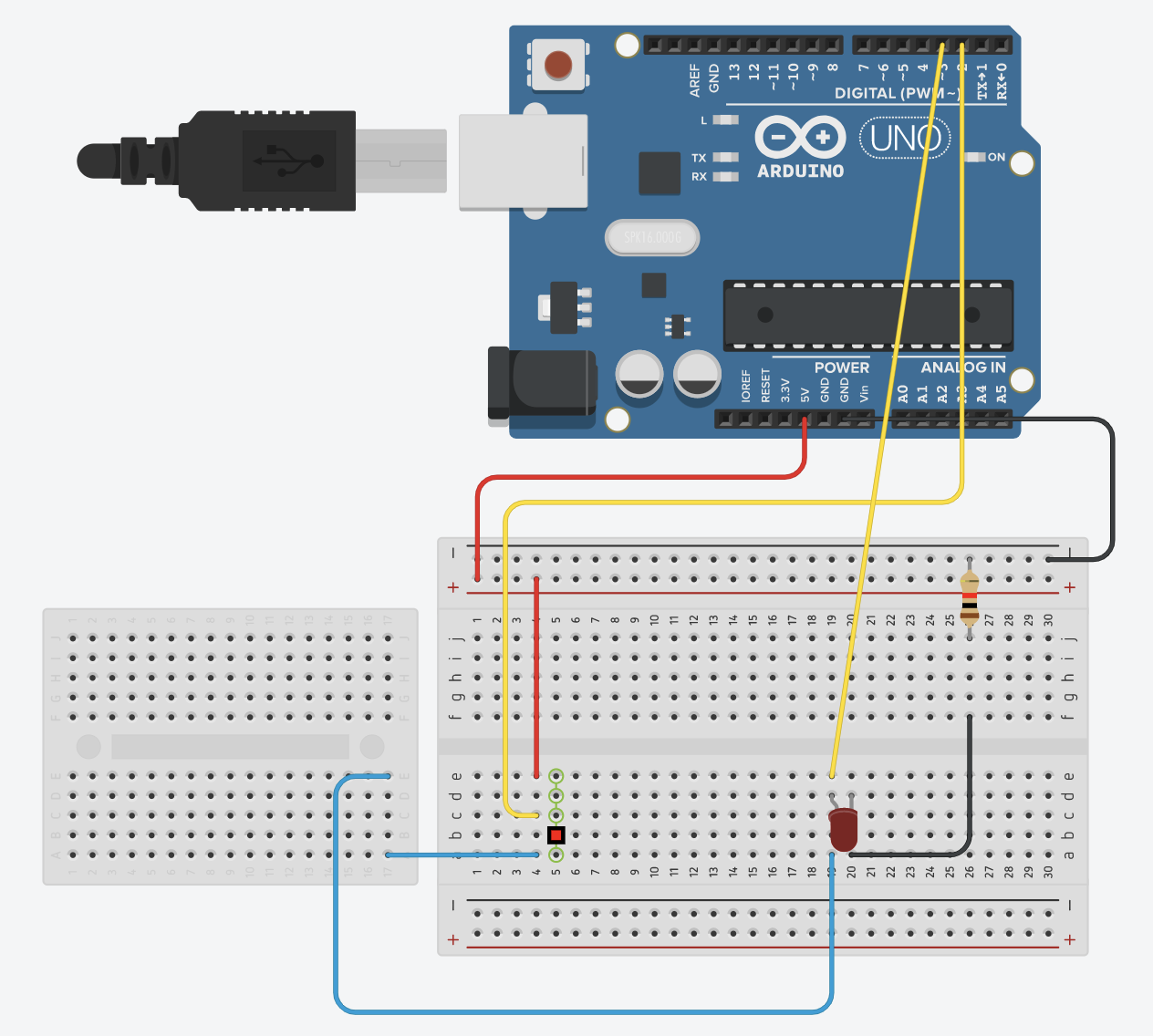
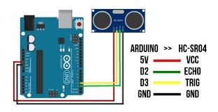
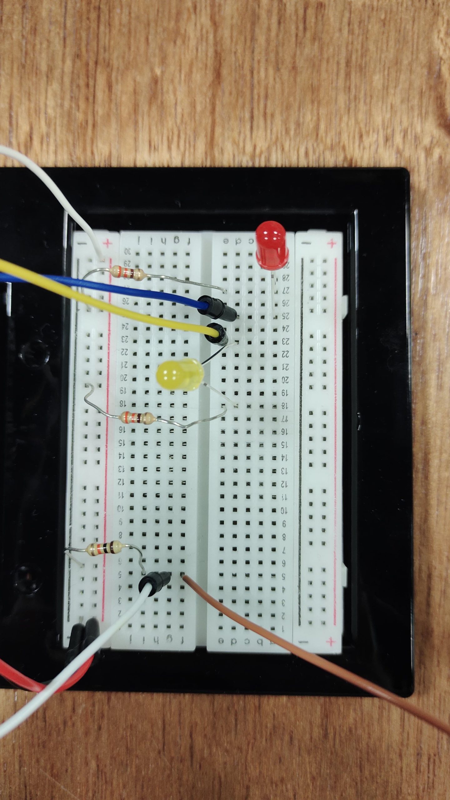
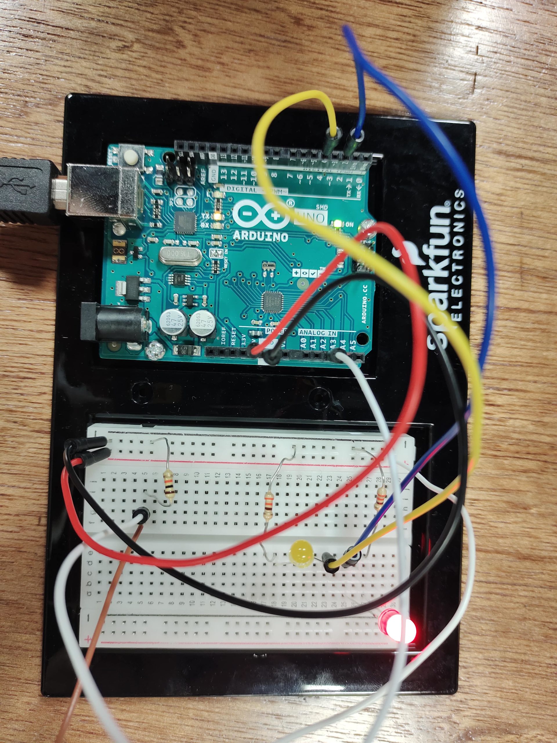
servo.attach(9);
pinMode(3, OUTPUT);
Serial.begin(9600);
// set the durations with a random coinflip
for (int i = 0; i < 10; i++) {
int coinFlip = random(2);
if (coinFlip == 0)
durations[i] = 8;
else
durations[i] = 4;
}
}
void loop() {
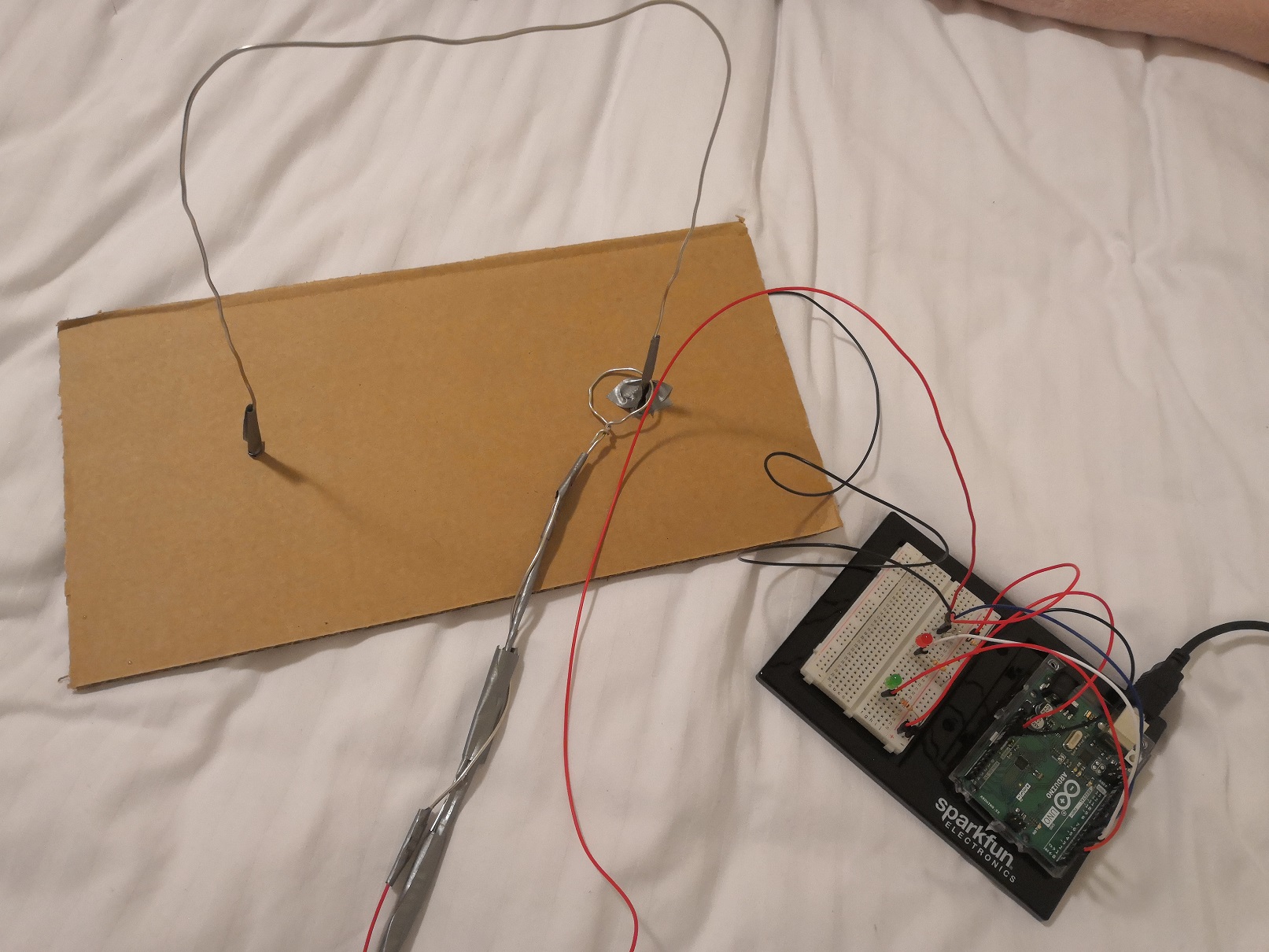
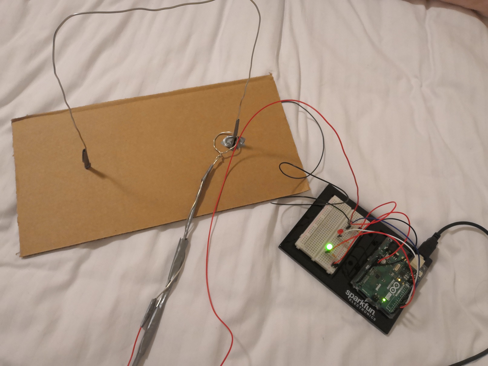
int val = analogRead(A0);
// the rate is 1 second divided by the duration of the note
int rate = 1000 / durations[whichNote];
// get the current time
unsigned long currentTime = millis();
// trigger a note
if (currentTime % rate == 0 ) {
tone(4, notes[whichNote], random(100, 400));
whichNote = random(10);
delay(1);
}
// do the servo at half speed
if (currentTime % (rate * 2) == 0 ) {
servoPos = 50;
servo.write(servoPos);
}
// else if not triggereing the servo, then every 10 milliseconds move the servo arm back a little bit
// can't do it every frame as that is too fast for the servo
else if (currentTime % 10 == 0) {
servoPos -= 1;
servo.write(servoPos);
}
}
- Timer0 – used for millis(), micros(), delay() and PWM on pins 5 & 6
- Timer1 – used for Servos, the WaveHC library and PWM on pins 9 & 10
- Timer2 – used by Tone and PWM on pins 3 & 11