I struggled to think of something creative to make, but I eventually settled on a kind of game where a red, a green, and a blue LED would light up, each with a random brightness, and then the player would have to use a potentiometer to control the brightnesses of each of the three LEDs in order to match the random brightness that they had. If the player was within a certain range, a green LED would light up, signifying that the player was correct, otherwise a red LED would light up signifying that the player was too far off.
Process:
I used some of the code from the Maintain State circuit we built, along with some from the Analog LED circuit from class as well.
Challenges:
My idea was quite complicated, especially for someone new at coding like me, and I spent too long trying to work it out. I eventually realized that I could have the same process with a blue LED that the player would control, which would make the circuit much simpler. I simplified my code and rebuilt my circuit, although for some reason, I encountered the same problem I had before, which was that all three LEDs would light up, and neither the button nor the potentiometer would change that.
I tinkered a little more, and the video shows as far as I got, however because I spent so much time on the more complicated version of this idea, I did not have enough time to completely troubleshoot either the code or the circuit. I had initially thought for a long time that the problem must have been somewhere in the code, but I think now that it might be in the circuit.
Final Work:
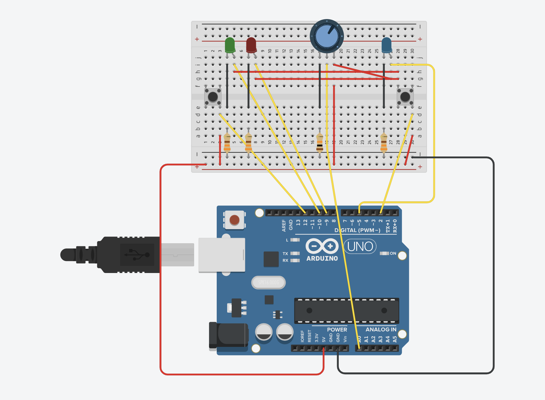
Diagram of my circuit on TinkerCAD
Code:
//potentiometer
const int knob = A0;
//target blue LED
const int bled = 5;
//incorrect and correct LEDs
const int iled = 9;
const int cled = 10;
//blue button
const int bbutton = 2;
//on/off button
const int obutton = 12;

bool bledOn = false;
bool iledOn = false;
bool cledOn = false;

//on off button
bool oButtonOnOff = false;
bool oButtonPrevOnOff = LOW;

//blue button
bool bButtonOnOff = false;
bool bButtonPrevOnOff = LOW;

void setup() {
  // put your setup code here, to run once:

  Serial.begin(9600);
  pinMode(bled, OUTPUT);
  pinMode(iled, OUTPUT);
  pinMode(cled, OUTPUT);
  pinMode(bbutton, INPUT);
  pinMode(obutton, INPUT);

}

void loop() {
//turning the LED on and off with the BLACK button
  bool oButtonCurrentState = digitalRead(obutton);
  int randomLED = random(255);
  if(oButtonCurrentState == HIGH && oButtonCurrentState != oButtonPrevOnOff){
    digitalWrite(bled, randomLED);
  }
  oButtonPrevOnOff = oButtonCurrentState;
  bledOn = !bledOn;

//turning the LED on and off with the BLUE button
  bool bButtonCurrentState = digitalRead(bbutton);
  if(bButtonCurrentState == HIGH && bButtonCurrentState != bButtonPrevOnOff){
    digitalWrite(bled, 255);
  }
  bButtonPrevOnOff = bButtonCurrentState;
  bledOn = true;

  int knobValue = analogRead(knob);
  //fix high and low based on potentiometer
  int mappedValue = map(knobValue, 850, 350, 0, 255);
  int constrainedValue = constrain(mappedValue, 0, 255);

  digitalRead(bled);
  if(bled == HIGH && bButtonPrevOnOff == HIGH){
    analogRead(knob);
    analogWrite(bled, constrainedValue);
  }

  int bledValue = analogRead(bled);
  if(bButtonCurrentState == HIGH &&  (randomLED - 5) < (bledValue) < (randomLED + 5)){
    bool cledOn = !cledOn;
  }
  if(bButtonCurrentState == LOW &&  (bledValue) < (randomLED - 5) || (randomLED + 5) < (bledValue)){
    iledOn = !iledOn;
  }
}
Our task in this report is to get information from at least one analog sensor and at least one digital sensor (switch), and use this information to control at least two LEDs, one in a digital fashion and the other in an analog fashion, in some creative way.
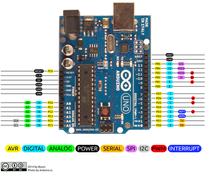
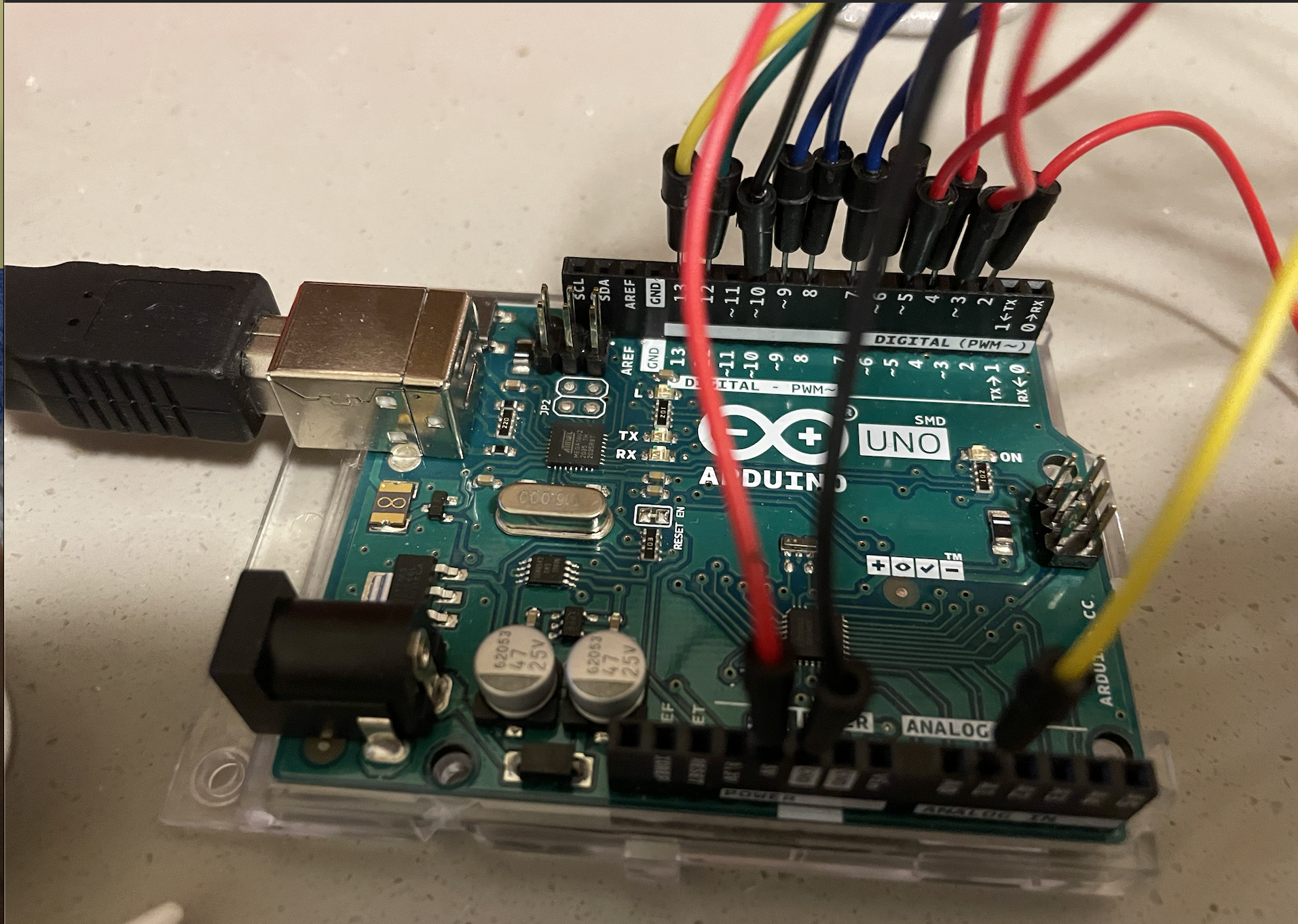
I will use the Arduino prototyping board for the digital and analog input and output for the interaction.
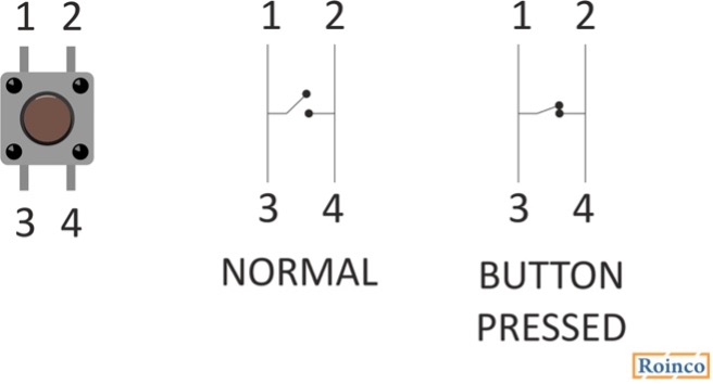
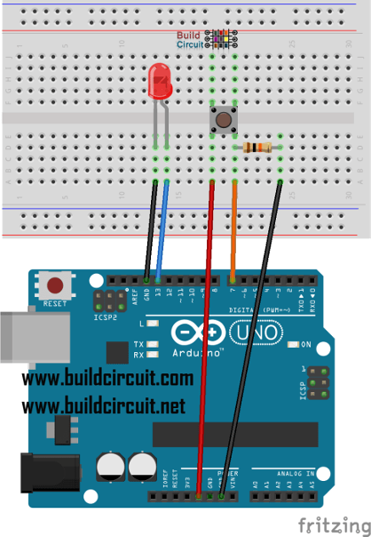
For the digital input I will use a push button.
For the digital output a LED is used.
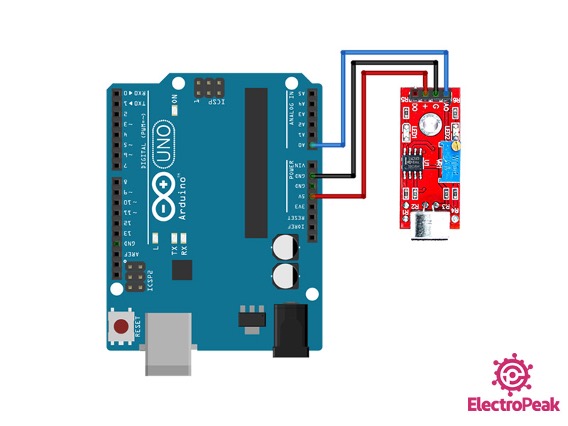
For the analog input a sound sensor is used.
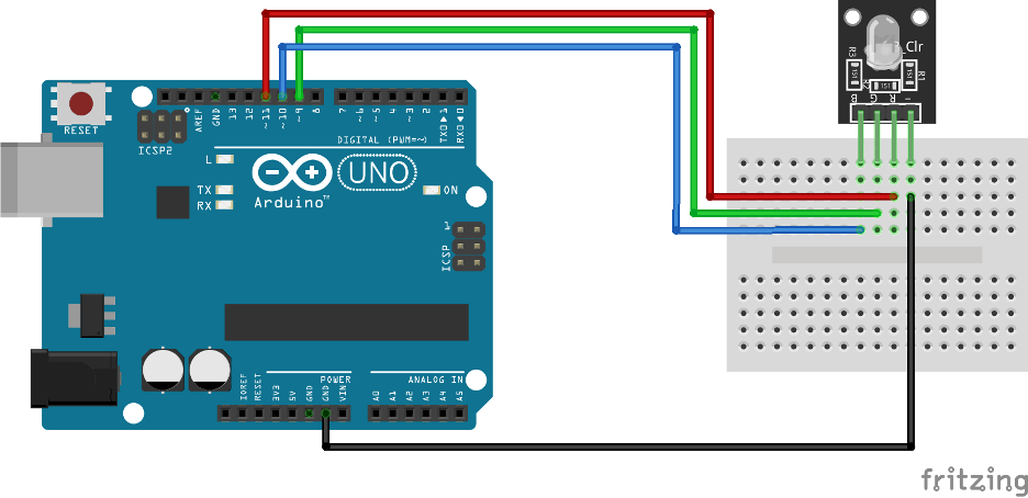
For the analog LED output an RGB LED is used.
Challenged Faced
The first challenge faced is to identify the needed input and output devices.
After researching the available simple devices, I decided on using buttons, sound sensor, LED and RGB LED.
The pins used for digital are the integer pins in the Arduino. The analog pins are pin A0 to A5 on the Arduino.
The second challenge was to do the circuit and connection required. I used tutorials from Arduino forums in order to connect the circuit.
The third challenge was to code the Arduino , using the Arduino IDE I wrote a code in C to program the Arduino.
Video:
Procedure
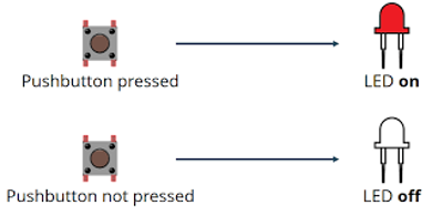
Step 1 : Button with LED output
Digital input controlling a digital input button.
Connecting the button:
The button is connected to pin 7 through a resistor of 1 kohm.
Step 2 : LED Digital
The connection of the LED is to the digital pin 13.
Code for connecting the button and the led:
int ledPin = 13; // The LED is connected to pin 13
int button = 7; // The button is connected to pin 7
int val = 0;
void setup () {
   pinMode (ledPin, OUTPUT); // The LED pin is an output
   pinMode (button, INPUT); // The pin of the button is an entry
   }
void loop () {

   val = digitalRead (button); // Reading the button

   if (val == 1) {// If the value of the button is 1
     digitalWrite (ledPin, HIGH); // Turn on the LED
   }
   else {// Otherwise:
     digitalWrite (ledPin, LOW); // Turn off the LED
   }
}
Step 3 : Input analog
The analog input I are using is a sound sensor KY-037
It is connected to A0 analog pin on Arduino.
Step 4: Analog output
As analog output I will use the 4 pin RGB LED.
In order to make it easier to connect it, I will use a module of RGB light: KY-016 RGB FULL COLOR LED MODULE.
The module is an RGB 4 pin LED connected to 3 resistor each of 150ohm to protect the pins.
This module uses PWM in order to send analog signals to the LED to turn on in different colors.
The connection is done as per the table below:
Pins
Arduino Pin
R
Pin 11
B
Pin 10
G
Pin 9
GND
GND
The code to control the RGB light is first to write in the setup:
void setColor(int red, int green, int blue)
{
//use PWM to controlt the brightness of the RGB LED
analogWrite(redPin, red);
analogWrite(greenPin, green);
analogWrite(bluePin, blue);
}
Now I can use the setcolor function in the Arduino loop code to change the color depending on different functions.
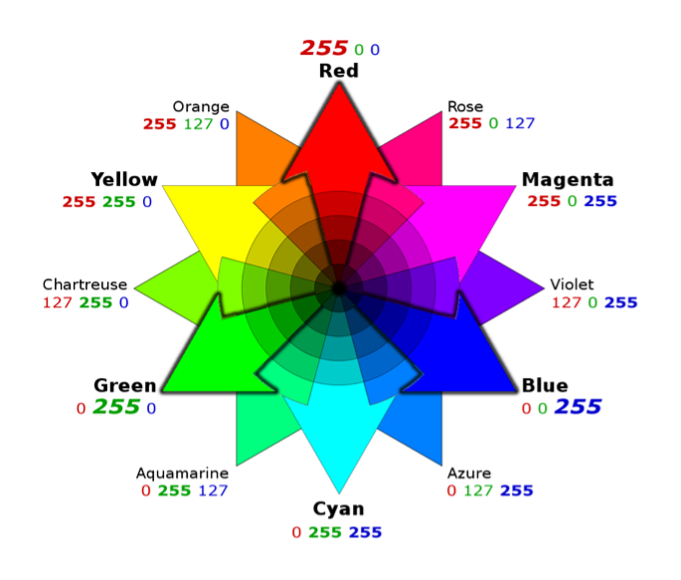
I programmed it depending on the sound of the sensor:
sound lower than 25 : no color
sound between 25 and 30 : yellow color
sound higher than 30 : red color
Using the code for colors:
setColor(255, 0, 0); // red
setColor(0, 255, 0); // green
setColor(255, 255, 0); // yellow
Final Outcome:
The circuit is built now and all inputs and outputs are working.
In order to give it a mission, I designed the code as the following:
SQUID GAME green and red light
Rule of the game: the player should press the button when the red light is on
Winner: blue lights turns on
When squid game starts, the sound sensor detects it and start a sequence:
-Green light is on
-Green is off and Red light is on for a short time: in this time the player should press the button
-if the player pressed the button while the red light was on, he will win
-if the player wins both lights will be blue indicating a win
-if the player doesn’t press in time, no blue light is on, so he lost.
Rule of the game: the player should press the button when the red light is on
As I completed this project I learned about different inputs and outputs and how the Arduino could be used to have different applications.
Squid Game Code
int ledPin = 13; // The LED is connected to pin 13
int button = 7; // The button is connected to pin 7
int val = 0;
int redpin =11;
int bluepin=10;
int greenpin=9;
void setup () {
pinMode (ledPin, OUTPUT); // The LED pin is an output
pinMode (button, INPUT); // The pin of the button is an entry
pinMode(redpin, OUTPUT);
  pinMode(bluepin, OUTPUT);
  pinMode(greenpin, OUTPUT);
  Serial.begin(9600);
setColor(0, 0, 0);
}
void loop () {
int sound = analogRead(A0);
Serial.print(sound); Serial.println(" Sound");
//if (sound<40) setColor(, 0, 0);//green
//else if (sound<42) setColor(255, 255, 0); //yellow
//else if (sound>42) setColor(255, 0, 0); //red
if (sound>42)
{ setColor(255, 255, 0);
delay(5000);
setColor(255, 0, 0);
delay(2000);
val = digitalRead (button); // Reading the button
if (val == 1) {// If the value of the button is 1
digitalWrite (ledPin, HIGH); // Turn on the LED
setColor(0, 0, 255);
delay(2000);
digitalWrite (ledPin, LOW);
}
else {// Otherwise:
digitalWrite (ledPin, LOW); // Turn off the LED
delay(2000);
}}
else setColor(0, 0, 0);
}
void setColor(int red, int green, int blue)
{
//use PWM to controlt the brightness of the RGB LED
analogWrite(redpin, red);
analogWrite(greenpin, green);
analogWrite(bluepin, blue);
}
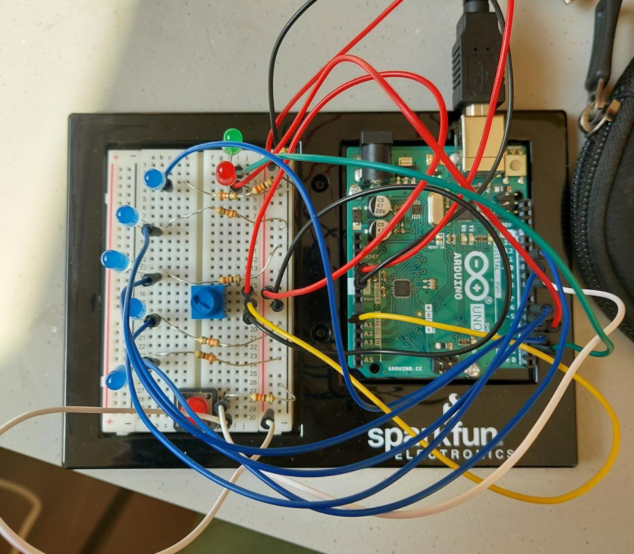
For this week’s assignment, I struggled a lot to come up with an idea, because I’ve never really had to think creatively in this medium (this case, arduino and LEDs), so it took a lot of brainstorming to conclude on an idea. I finally settled on a guessing game. It is a game you play wherein the code chooses a random bulb on the board, and you, as a player, have to guess which bulb it is. If you guess right, you win!
I used a potentiometer to get the analog input and a push-button for the digital input. I settled on five blue LEDs in total and the player has to guess which LED is the secret LED. There are green and red LEDs on the board that will indicate whether the chosen LED is correct. The choice is decided by rotating the knob on the potentiometer. And the choice is finally sealed in by pressing the push button.
Also, I wanted to put in some breather time in between two games and also when the game begins. I really liked the idea of showing patterns through LEDs, so I decided to make a pattern through the blue LEDs at the beginning of the game to settle in, and between games when whether the player is right or wrong is indicated.
Making the circuit was easier than I had anticipated. I imagined the absolute worst scenarios when I decided on the idea, but it helped me seal the concepts learned in class, so it went along better than expected 🙂
One problem I faced was the placement of the different elements on the board because at first I put in all the elements on one end of the board and it became very crowded, so I changed the placement and put in the potentiometer in the middle. While it can be troublesome to move in between the wires, it is intuitive in relation to the 5 LEDs surrounding it because the mapping is quite obvious.
Here’s the circuit:
For the code itself, I divided the game into 4 different parts and worked on them one at a time, tested it, and then integrated it with whatever I had done until before and tested again.
The parts where:
the patterns by the 5 blue LEDs
potentiometer mapping to the 5 LEDs
sealing the deal with the switch and checking whether the guess was right (and lighting the corresponding LED)
Resetting the game to restart
Serial.print helped a lot with error correction. I had some trouble with the pushbutton and the resetting of the game. So, in addition to setting the numbers for mapping the knob value to the corresponding LED, the logs helped with the switch error too. The error I had was related to delays in the pattern function. While the pattern was still going on, the checking for the next guess would proceed, and this would cause the green/red bulb to light again. But this was a premature checking step as the player hadn’t chosen their next guess yet. So, I changed the code to make sure that all the variables were reset as soon as the push button was pressed and the pattern was called at the end of the game rather than executing the loop I had for the pattern at the beginning of the game (since it was too late by then). This solved all problems.
Something I hadn’t realized before was that with analog input, I could also use the same for digital input too. While we did learn this in class, it hadn’t properly set in my mind until I did that with the code. I used digitalWrite for the 5 LED bulbs with the patterns in the beginning and analogWrite for the same bulbs when guessing the number.
Here’s a demo:
Here’s the code:
const int lightVis = 75;
const int num = 7;
int lightPins[7] = {2,3,4,5,6,10,11};
const int switchPin = 8;
const int knob = A0;
bool startPat = false;
int pins[5]={1,3,4,5,6};
int randNumber = pins[random(5)];
bool gameOver = false;
bool prevButtonState = false;


void setup() {
  Serial.begin(9600);
  for(int i=0;i<num;i++)
  {
    pinMode(lightPins[i],OUTPUT);
  }
  pinMode(switchPin,INPUT);
}


void loop() {
  bool currentState = digitalRead(switchPin);

  //pattern
  if( startPat == false){
  for(int i=0; i<=5; i++) {
     pattern();
     startPat = true;
  }
  }

  //green and red lights are now OFF
  digitalWrite(lightPins[2], LOW);
  digitalWrite(lightPins[0], LOW);

 //mapping knob values to corresponding LED
  int knobValue = analogRead(knob);
  int ledNum;
  if ((knobValue>0 && knobValue<435) || knobValue<0)
    ledNum=6;
  if (knobValue>435 && knobValue<700)
    ledNum=5;
  if (knobValue>700 && knobValue<755)
    ledNum=4;
  if (knobValue>755 && knobValue<838)
    ledNum=3;
  if (knobValue>838)
    ledNum=1;


  Serial.print("Random Value: ");
  Serial.print(randNumber);
  Serial.print(" Knob Value: ");
  Serial.print(knobValue);
  Serial.print(" Mapped Value:");
  Serial.print(mappedValue);
  Serial.print(" ");
  Serial.print(currentState);
  Serial.print(" ");
  Serial.println(prevButtonState);

  analogWrite(lightPins[ledNum],254);
  for(int i=0; i<num; i++) {
     if(i!=ledNum){
        analogWrite(lightPins[i],0);
     }
  }


  if (currentState != prevButtonState && currentState==HIGH) {
    gameOver=true;
    if(ledNum==randNumber){
      digitalWrite(lightPins[0], HIGH);
      digitalWrite(lightPins[2], LOW);
    }
    else{
      digitalWrite(lightPins[2], HIGH);
      digitalWrite(lightPins[0], LOW);

    }
    prevButtonState = false;
    currentState=false;
  }


  if(gameOver)
  {

    randNumber = pins[random(5)];
    gameOver = false;
    for(int i=0; i<=5; i++) {
     pattern();

  }

  }

}


void pattern(){
    for(int i=0; i<num; i++) {
      if(lightPins[i]!=2 && lightPins[i]!=4)
      {
        digitalWrite(lightPins[i],HIGH);
        delay(lightVis);
        digitalWrite(lightPins[i],LOW);
      }

    }

    for(int i=num-1; i>=0; i--) {
      if(lightPins[i]!=2 && lightPins[i]!=4)
      {
        digitalWrite(lightPins[i],HIGH);
        delay(lightVis);
        digitalWrite(lightPins[i],LOW);
      }
    }
}
This will be a fun replacement for heads or tails. I’ve used heads/tails toss to make a lot of arbitrary decisions before, but I’m thinking that in situations wherein I’m leaning against a particular choice, this would be a great way to make a decision as there’s only a 1/5th chance of getting it right! But if you do guess right, even probability isn’t on your side ://
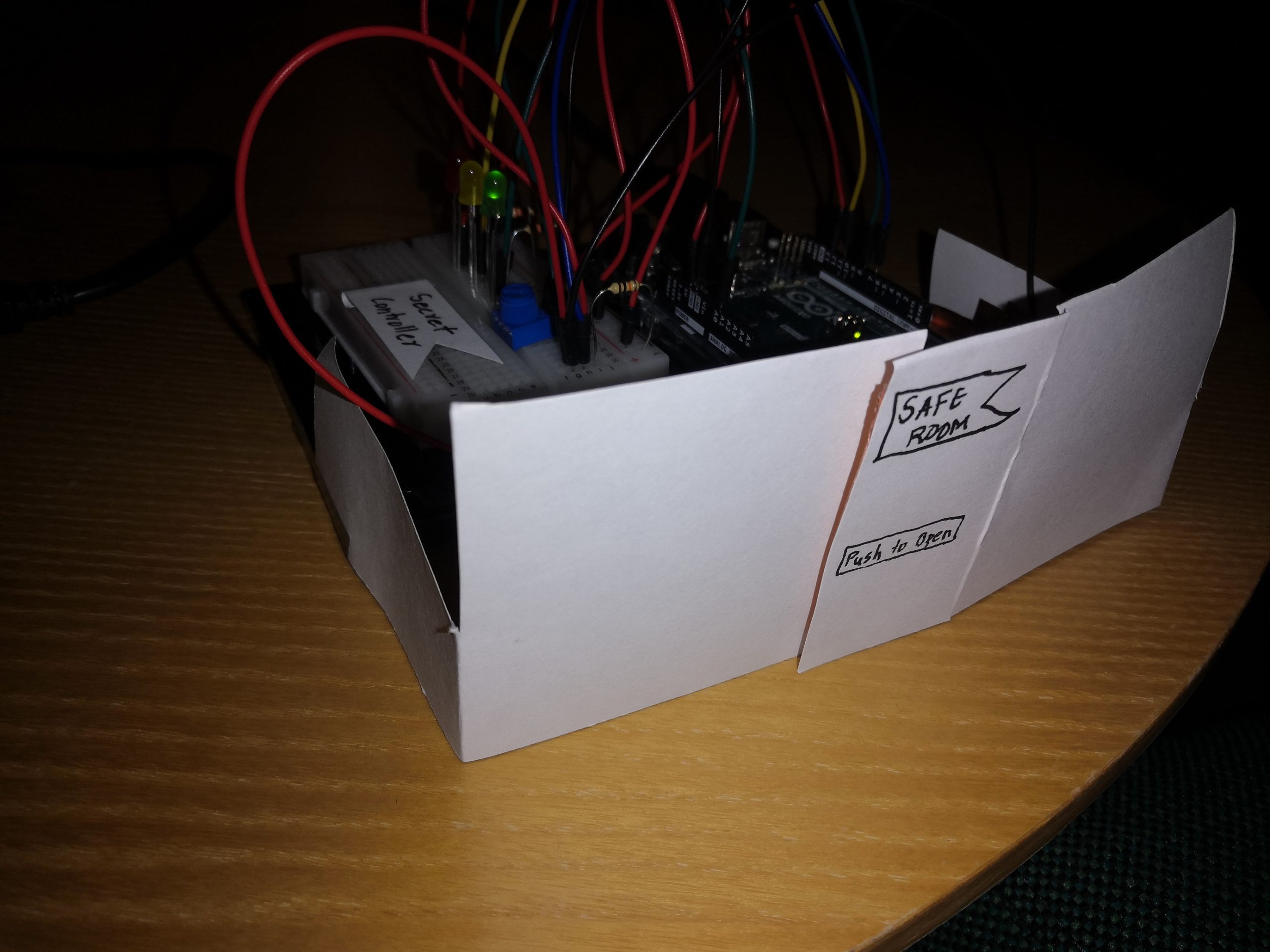
This week, I designed a safe room using Arduino. The requirement was to create a circuit that will get information from at least one analog sensor and at least one digital sensor (switch) and use this information to control at least two LEDs, one in a digital fashion and the other in an analog fashion, in some creative way.
So, my creative idea involves a safe room that has a hidden secret controller. Every time someone enters the room, an intermediate warning is issued and the individual has 45 seconds to locate the hidden controller and adjust it to avoid triggering the security alarm. The location is highly confidential and only the top-tier managers know information. In case of an intruder, unless he is exceptionally smart enough to locate and adjust the controller, the person will be caught by this highly advanced security system.
Technical Implementation
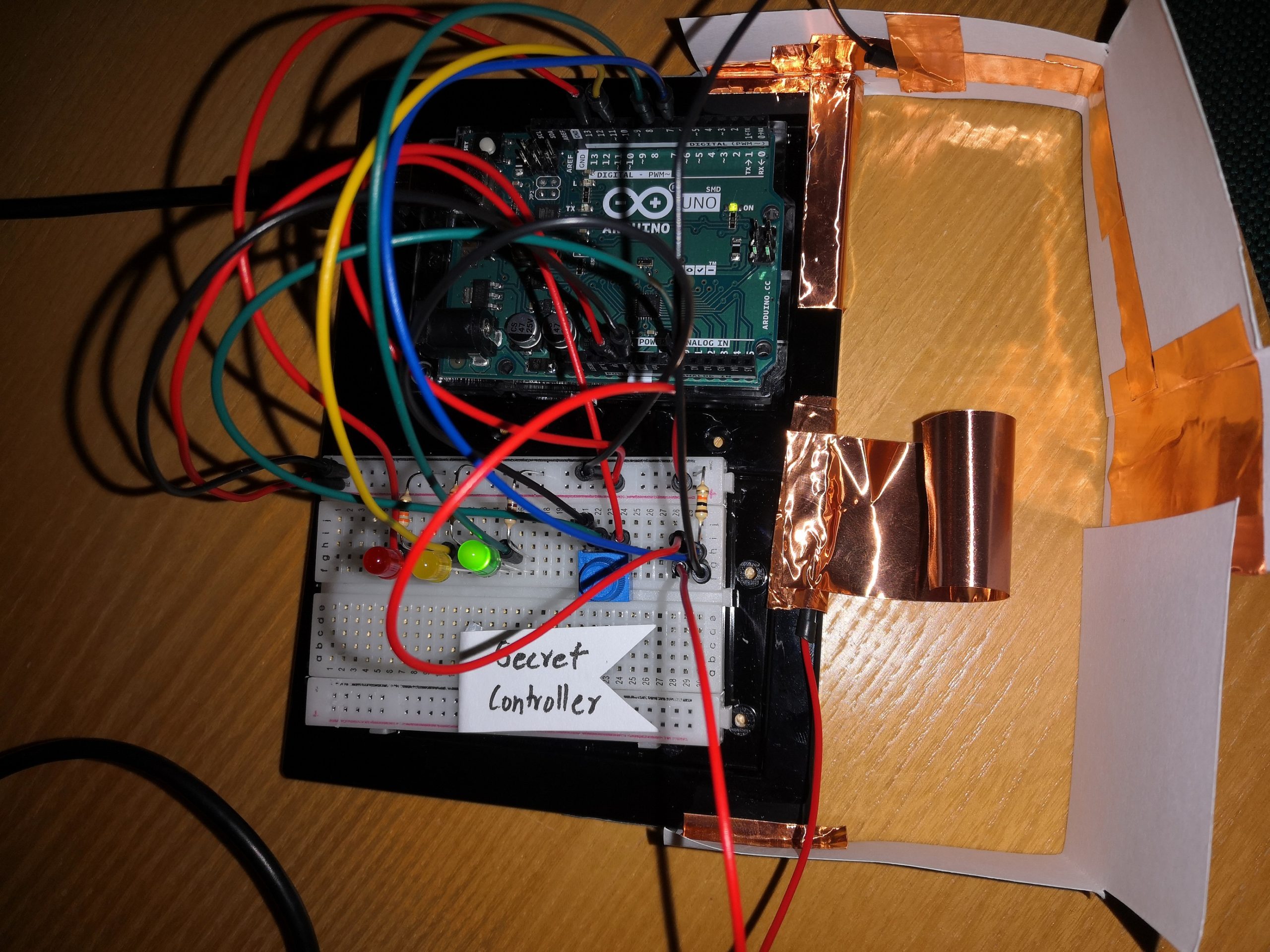
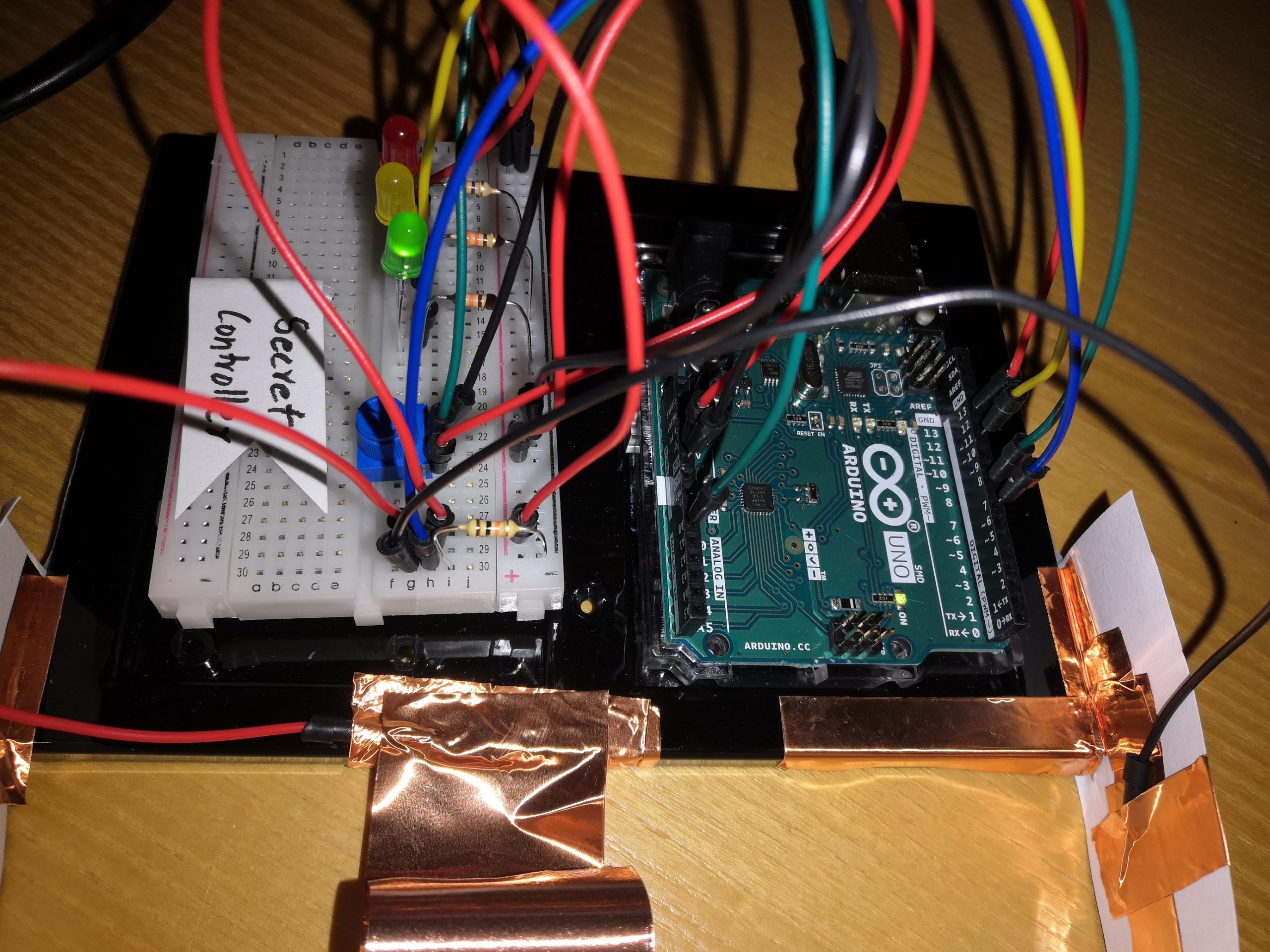
One of the biggest challenges was to implement the idea on paper using the Arduino. After breaking into smaller steps, I figured it out. The digital switch was made using copper tape, one end on the board and one connected to the door. Once the door is open, it would send a HIGH to the connected digital input pin. Upon this, the always-on green light stops, and the yellow led starts glowing. Yellow led is controlled by the potentiometer (the controller). In the start it is set to a value of 1023 – the bright yellow led and the individual has to switch off the led entirely using the potentiometer – to the value of 0. A timer is initiated as soon as the door is open and the individual has 45 seconds – 45000 milliseconds – to complete this. If the individual is successful, the green led turns back on. Otherwise, the red led is turned on digitally which signifies triggering the security alarm.
Here is the circuit:
Here’s the code:
//Global variable
const int knob = A0;
const int red_led = 13;
const int yellow_led = 11;
const int green_led = 8;
const int input = 7;
int starttime;

void setup() {
  //setting the modes
  pinMode(red_led, OUTPUT);
  pinMode(yellow_led, OUTPUT);
  pinMode(green_led, OUTPUT);
  pinMode(input, INPUT);

  //start timer
  starttime = millis();

  Serial.begin(9600);

}

void loop() {

  //when door is open
  if(digitalRead(input)==HIGH){
    //turn off the green led
    digitalWrite(green_led,LOW);
    //turn the yellow led on
    //control it anlogue way
    int knobValue = analogRead(knob);
    int mappedvalue = map(knobValue,0,1023,255,0);
    analogWrite(yellow_led,knobValue);

    //keep count of the time elapsed since the door is open
    Serial.print("millis elapsed : ");
    Serial.println(millis()-starttime);
    if((millis()-starttime) >= 45000){
      //if not controlled within time, trigger the alarm
      if(analogRead(knob) > 0){
        digitalWrite(red_led, HIGH);
      }
      //green switch back on successful completion
      else{
        digitalWrite(green_led, HIGH);
      }
    }
  }
  else{
    //if door closed, keep yellow light off and green on
    if(digitalRead(red_led) != HIGH){
      digitalWrite(yellow_led,LOW);
      digitalWrite(green_led,HIGH);
      Serial.println("You have 45 seconds to find and adjust the secret controller. Else alarm will go off!");
    }
  }
This is the video for when a known individual enters the room
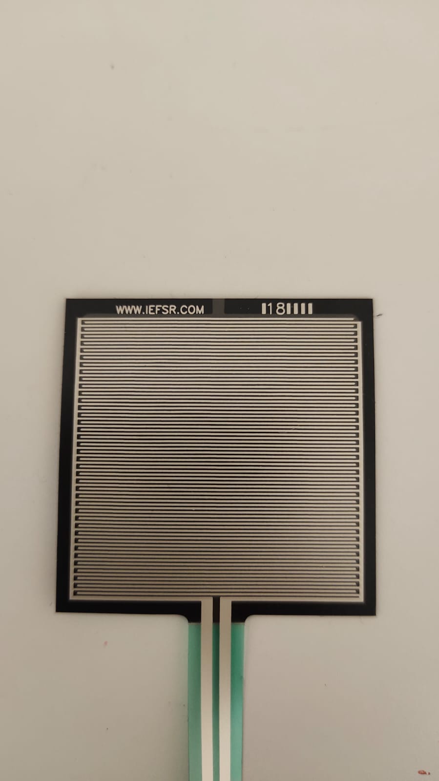
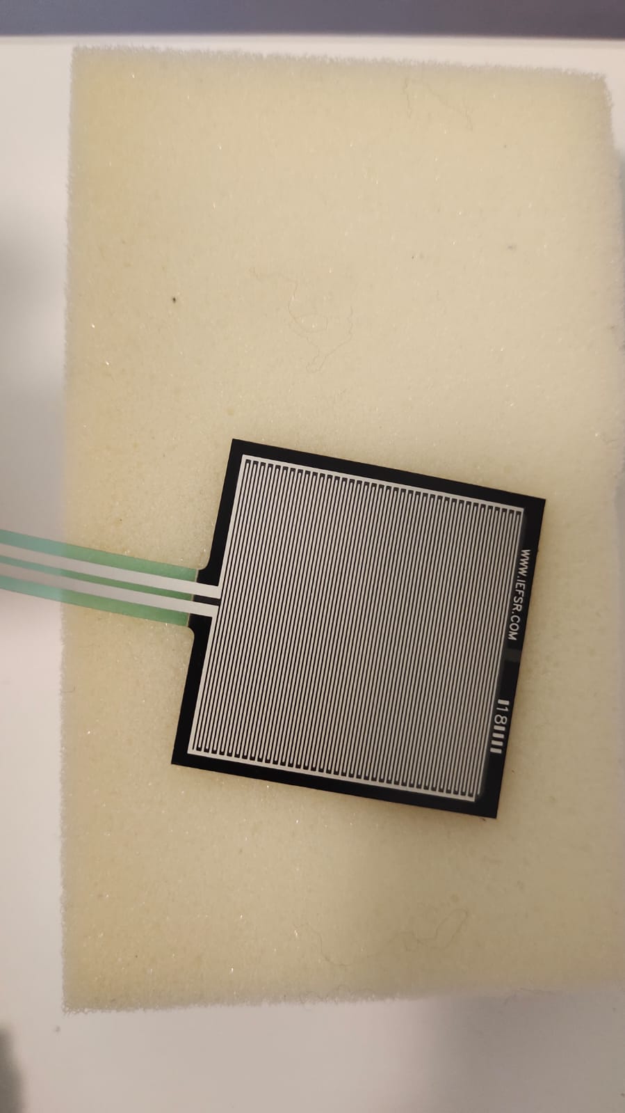
I decided, after a struggle of thought, to make a simple water refill reminder. Drinking water is crucial and many people tend to try to forget. So I made this simple water that detects the weight of the bottle and knows how much water is left in the bottle/cup using a force sensor.
using the force sensor on its own did not give a range of weight enough for the water weight detector. so I decided to place the force sensor on a sponge.
I also used an on/off button that turns the circuit on when pressed and off when pressed once more
I also used 4 red lights that are more likely to capture someone’s attention and remind them to refill their water bottle when it’s empty.
and I used 4 blue led lights, more of the blue lights light up the more water there is in the bottle.
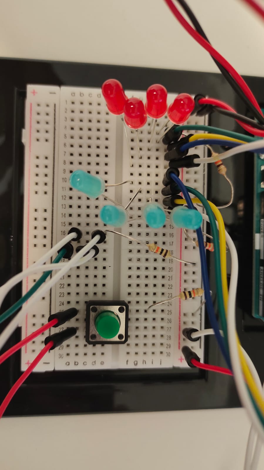
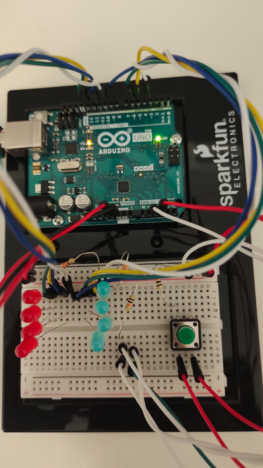
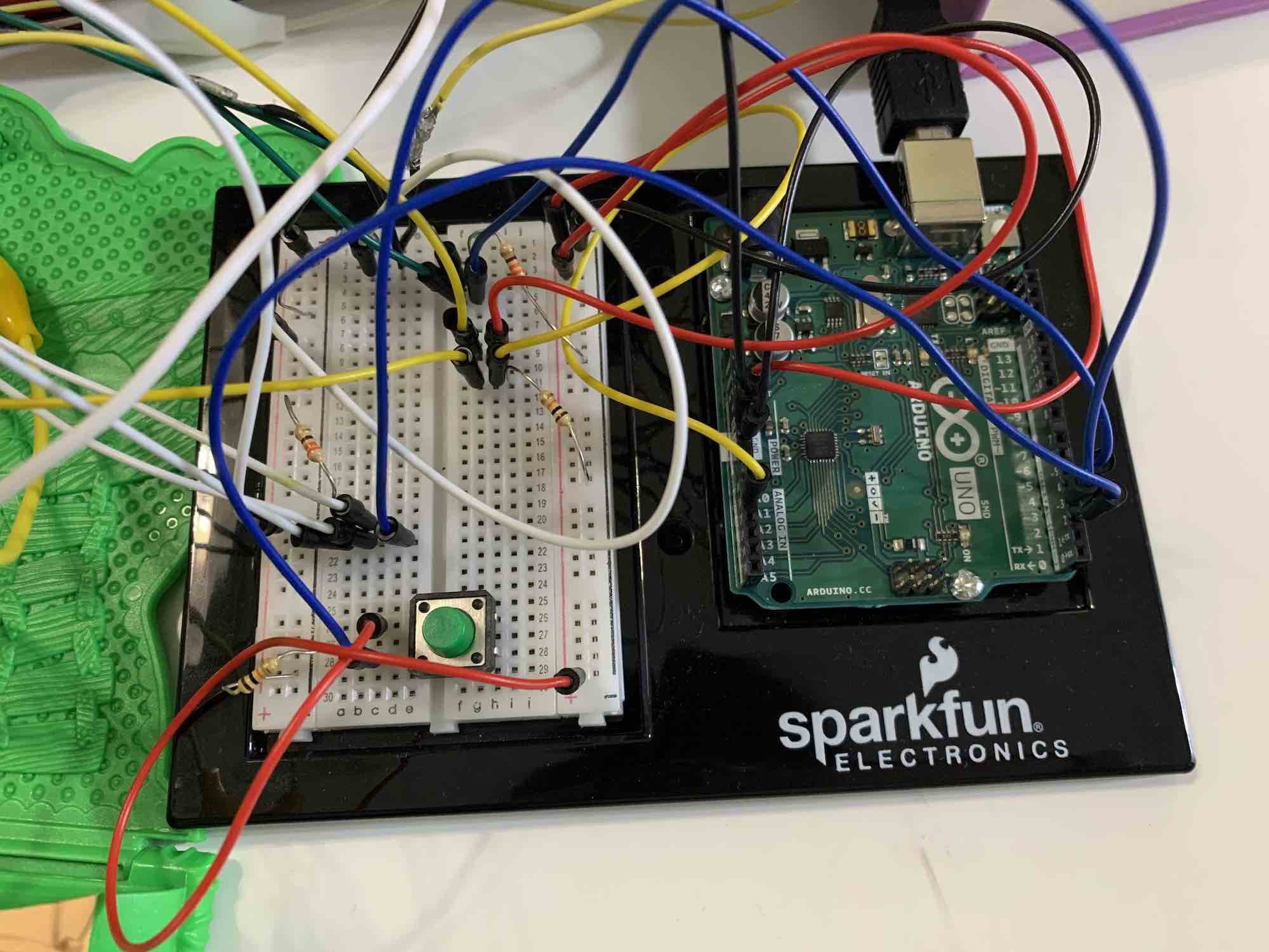
this is how my circuit looks:
the last set of wires that are neither connected to the button or the less is connected to the force sensor.
video:
the video shows how the circuit works:
Code:
const int outs[] = {3, 5, 6, 9,
                    10, 11, 12, 13
                   };
const int ins[] = {A2, A3};
int var, var2, b, r, maxx = 0;

long timer;
bool turnon = 0, curr, prev;

void setup() {
  Serial.begin(9600);
  for (int i = 0; i < sizeof(outs); i++) {
    pinMode(outs[i], OUTPUT);
  }
  Serial.begin(9600);
  for (int i = 0; i < sizeof(ins); i++) {
    pinMode(ins[i], INPUT);
  }
}

void loop() {
  if (curr != prev && curr == 1) {
    turnon = !turnon;
  }
  curr = digitalRead(ins[1]);
  timer = millis();
  var = analogRead(ins[0]);//0-250
  var = map(var, 0, 500, 0, 255);
  var2 = constrain(var, 250, 255);
  Serial.print(" on: ");
  Serial.print(turnon);
  Serial.print(" curr: ");
  Serial.print(curr);
  Serial.print(" prev: ");
  Serial.println(prev);


  if (turnon == 1) {
    on();
  }
  else {
    for (int i = 0; i < 8; i++) {
      analogWrite(outs[i], 0);
    }
  }
  //
  prev = digitalRead(ins[1]);

}

void redled(int n) {
  if (timer % (n * 4) < (n * 1)) {
    analogWrite(outs[4], var2);
    analogWrite(outs[5], 0);
    analogWrite(outs[6], 0);
    analogWrite(outs[7], 0);
  }
  else if (timer % (n * 4) < (n * 2)) {
    analogWrite(outs[4], 0);
    analogWrite(outs[5], var2);
    analogWrite(outs[6], 0);
    analogWrite(outs[7], 0);
  }
  else if (timer % (n * 4) < (n * 3)) {
    analogWrite(outs[4], 0);
    analogWrite(outs[5], 0);
    analogWrite(outs[6], var2);
    analogWrite(outs[7], 0);
  }
  else {
    analogWrite(outs[4], 0);
    analogWrite(outs[5], 0);
    analogWrite(outs[6], 0);
    analogWrite(outs[7], var2);
  }
}

void on() {

  if (var < 20) {
    b = -1;
    r = 4;
  }
  else if (var < 140) {
    b = 0;
    r = 0;
  }
  else if (var < 260) {
    b = 1;
    r = 0;
  }
  else if (var < 380) {
    b = 2;
    r = 0;
  }
  else {
    b = 3;
    r = 0;
  }

  // there is water
  if (r == 0) {
    for (int i = 0; i < b + 1; i++) {
      analogWrite(outs[i], var2);
    }
    for (int i = 7; i > b; i--) {
      analogWrite(outs[i], 0);
    }
  }
  else {
    for (int i = 0; i < 4; i++) {
      analogWrite(outs[i], 0);
    }
    redled(1000);

  }
}
For this week’s task, I used several LEDs, a photoresistor, and a button to simulate a rare event in Abu Dhabi: rain.
LEDs:
I used four colors of LEDs:
blue to represent rain
red and yellow to represent the social chaos caused by the rain;
green to represent the calm state of no rain
The blue and green LEDs are connected individually in parallel, while the other six red and yellow LEDs are connected in pairs of series, which are then connected in parallel.
Photoresistor:
For this task, I thought that using the values read directly from the photoresistor would not make sense because I’m only considering two states: rain and no rain. For this reason, I decided to set threshold variables. If the photoresistor value exceeds the variable, then it is considered not raining, and if the photoresistor value is lower than the threshold then it is considered raining. This can also be abstracted as the presence or lack of rain clouds.
Button:
The button in this task represents some control over the chaos (yellow and red LEDs) present while it’s raining. If it is raining and the button is pressed, then the chaos will stop. This can also be abstracted as some kind of enforcement of social distancing regulations which might be broken in the rain mayhem.
Limitations(?):
I had to change my threshold variable multiple times while working on the project because the lighting in my surroundings changed. I think for this project to work correctly, the threshold value has to be updated every time it is run.
const int knob = A0;
const int calmLed = 3;
bool raining = 0;
int threshold = 85
0;
int activeBlue = 0;
int buttonPin = 13;

void setup() {
  // put your setup code here, to run once:
  Serial.begin(9600);
  for (int i = 3; i <= 9; i++) {
    pinMode(i, OUTPUT);
  }
  pinMode(buttonPin, INPUT);
}

void loop() {
  // put your main code here, to run repeatedly:
  int buttonState = digitalRead(buttonPin);
  int knobVal = analogRead(knob);
  int mappedVal = map(knobVal, 420, 820, 0, 255);
  Serial.print("Knob Val: ");
  Serial.println(knobVal);
  Serial.print("Mapped Val: ");
  Serial.println(mappedVal);

  if (knobVal > threshold) {
    raining = 0;
  } else {
    raining = 1;
  }

  //control green light when not raining
  if (!raining) {
    //turn off all red, yello, and blue leds when not raining
    for (int i = 4; i <= 9; i++) {
      digitalWrite(i, LOW);
    }
    digitalWrite(3, HIGH);
    delay(500);
    digitalWrite(3, LOW);
    delay(500);
  } else {

    //control red and yellow leds when raining
    if (buttonState == LOW) {
      int x = 0;
      for (int i = 4; i <= 6; i++) {
        x = (int) random(0, 10);
        if (x > 7) {
          digitalWrite(i, LOW);
        } else {
          digitalWrite(i, HIGH);
        }
      }
    } else {
      for (int i = 4; i <= 6; i++) {
        digitalWrite(i, LOW);
      }
    }

    //control blue leds when raining
    int iterateBlue = (activeBlue % 3) + 7;
    digitalWrite(iterateBlue, HIGH);
    delay(200);
    digitalWrite(iterateBlue, LOW);
    activeBlue += 1;
  }
}
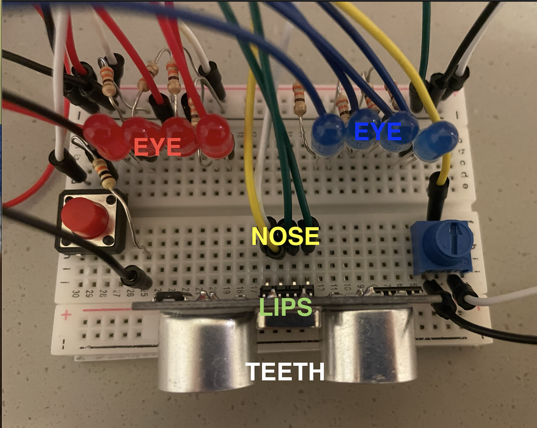
For this week’s assignment, I made a project that looks like a face of a robot, which has lights as its eyes, cables as nose and the distance sensor as mouth.
Normally, it looks straight at you, with the lights at the center of both sides on. If you turn the potentiometer left, the robot looks left, so the red lights are on. If you turn it right, the blue lights are on, showing that the robot is now looking right. If you move close to the robot’s face (mouth), it gets shy and closes its eyes, so the lights are all off.
If you press the button, the robot will enter into another state. Instead of looking at you, it starts processing data, so I have the delays between LEDs to show how data flows through. Then if you press again, it will go back to its original state.
Code
const int led1 = 2;
const int led2 = 3;
const int led3 = 4;
const int led4 = 5;
const int led5 = 6;
const int led6 = 7;
const int led7 = 8;
const int led8 = 9;
const int button = 10;
const int echo = 12;
const int trig = 13;
const int knob = A1;

int count = 0;
int ledState = LOW;
int buttonState1;
int buttonState2;
int de = 100;
bool off = false;

void setup() {
  // put your setup code here, to run once:
  Serial.begin(9600);
  pinMode(led1, OUTPUT);
  pinMode(led2, OUTPUT);
  pinMode(led3, OUTPUT);
  pinMode(led4, OUTPUT);
  pinMode(led5, OUTPUT);
  pinMode(led6, OUTPUT);
  pinMode(led7, OUTPUT);
  pinMode(led8, OUTPUT);

  pinMode(button, INPUT);
  pinMode(knob, INPUT);
  pinMode(trig, OUTPUT);
  pinMode(echo, INPUT);
  buttonState1 = digitalRead(button);
}

void loop() {
  buttonState2 =  digitalRead(button);
  if (buttonState2 != buttonState1) {
    if (buttonState2 == LOW) {
      count ++;
    }
  }
  buttonState1 = buttonState2;

  if (count%2 == 1) {
    ledState = HIGH;
  } else {
    ledState = LOW;
  }

  int knob_val = analogRead(knob);


  digitalWrite(trig, LOW);
  delayMicroseconds(2);
  digitalWrite(trig, HIGH);
  delayMicroseconds(2);
  digitalWrite(trig, LOW);

  int duration = pulseIn(echo, HIGH);
  int dist = duration/58.2;


  if (ledState == HIGH) {
    digitalWrite(led1, HIGH);
    delay(de);
    digitalWrite(led2, HIGH);
    delay(de);
    digitalWrite(led3, HIGH);
    delay(de);
    digitalWrite(led4, HIGH);
    delay(de);
    digitalWrite(led5, HIGH);
    delay(de);
    digitalWrite(led6, HIGH);
    delay(de);
    digitalWrite(led7, HIGH);
    delay(de);
    digitalWrite(led8, HIGH);

    digitalWrite(led1, LOW);
    delay(de);
    digitalWrite(led2, LOW);
    delay(de);
    digitalWrite(led3, LOW);
    delay(de);
    digitalWrite(led4, LOW);
    delay(de);
    digitalWrite(led5, LOW);
    delay(de);
    digitalWrite(led6, LOW);
    delay(de);
    digitalWrite(led7, LOW);
    delay(de);
    digitalWrite(led8, LOW);
  } else {
    int del;
    if (dist <= 10) {
      off = true;
    } else {
      off = false;
    }
    if (off) {
      digitalWrite(led1, LOW);
      digitalWrite(led4, LOW);
      digitalWrite(led5, LOW);
      digitalWrite(led8, LOW);
      digitalWrite(led2, LOW);
      digitalWrite(led3, LOW);
      digitalWrite(led6, LOW);
      digitalWrite(led7, LOW);
    } else {

    if (knob_val>300 and knob_val<630) {
      digitalWrite(led1, LOW);
      digitalWrite(led4, LOW);
      digitalWrite(led5, LOW);
      digitalWrite(led8, LOW);
      digitalWrite(led2, HIGH);
      digitalWrite(led3, HIGH);
      digitalWrite(led6, HIGH);
      digitalWrite(led7, HIGH);
    }
    if (knob_val<=300) {
      digitalWrite(led1, HIGH);
      digitalWrite(led4, HIGH);
      digitalWrite(led5, LOW);
      digitalWrite(led8, LOW);
      digitalWrite(led2, HIGH);
      digitalWrite(led3, HIGH);
      digitalWrite(led6, LOW);
      digitalWrite(led7, LOW);
    }
    if (knob_val>=630) {
      digitalWrite(led1, LOW);
      digitalWrite(led4, LOW);
      digitalWrite(led5, HIGH);
      digitalWrite(led8, HIGH);
      digitalWrite(led2, LOW);
      digitalWrite(led3, LOW);
      digitalWrite(led6, HIGH);
      digitalWrite(led7, HIGH);
    }
    }
  }


}
Challenges
Initially, instead of the distance sensor, I was going to use the LDR sensor as the robot’s nose. However, the light in the dorm was not suitable for it and the output of the LDR value was quite random. I couldn’t figure out how to use the photo cell properly, so I changed it to the distance sensor, which is more reliable 🙂 Then I readjusted the position and found that the cables could be the nose!
The challenge I encountered was how to arrange the elements to create a correct circuit. Since I had many parts on the board, I needed to be careful not to overlap the positions for power/ground, so that they don’t touch each other to form another circuit. Thanks to Professor Aaron, I successfully connected the button and also the distance sensor.
The code part was not so challenging, but it took me some time to figure out the logics. The order of the conditions in the codes was difficult to sort out.
Overall, I think I have learned a lot from this project and have a better understanding of how the circuits work, especially how the sensors work.
This week’s assignment was to use 2 or more LEDs, one analog and one digital. My project for this assignment is a light-up mini dollhouse, I just used a dollhouse I borrowed from my sister and connected all my wires and LEDs to it!
First, I connected everything on the breadboard and made my code to make sure everything works properly. Once everything worked, I started removing the LEDs and the photoresistor (which is my analog component) one by one and attach them to my dollhouse. To attach them, I mainly used alligator clips, copper tape and washi tape.
The photoresistor makes the LED brighter as the sensor picks up dimmer light, in other words, as your finger gets closer to the sensor, the LED gets brighter. The other two LEDs are controlled by the button, and I connected them in parallel so that they can both be bright. Once I connected the LEDs and the photoresistor to the dollhouse and the button to the breadboard, it worked out! yay!
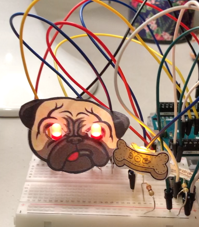
This idea came from me really missing my dog back home:(
If you are a dog owner you know they get really upset/angry when you stop petting them/being near to them. So I decided to use the ldr sensor (analog sensor) to imitate the motion of petting/being near to the dog. The dogs eyes start being lit up with red led light which portray the dogs anger, then when you get closer and touch the ldr sensor the dogs eyes stop glowing (he stops being mad). The touching of the sensor is like touching or petting the dog. Another option to make the dogs eyes stop glowing is giving him a treat which is portrayed using a yellow led light, when you click on the button (digital sensor) you give the dog the treat so his eyes stop glowing and he isn’t upset anymore!
Process:
First of all I wanted to get the more difficult part of the process out of the way which is the ldr. I used the basic way to make an ldr, and followed the steps on our blog. Then I used constrain (map) in order to get the led lights to dim and brighten up all the way. Where I map the values from half the max until the max of the photocell readings into 0 -> 255 so that as they increase the brightness increases, and constrain that within 0 to 255. hence fulfilling the analog fashion needed for the project. This is the video of the ldr sensor working alone before continuing the rest of the project.
I also extrapolated the power and the ground to the rest of the board using two jumper wires, in order to give myself extra space to work with. There I put the button digital switch to control the idea of the treat. The button is used to switch off the eyes as well and the yellow led with the treat on it, hence presenting the digital fashion needed for the project.
Finishing touches:
In order to show the story in a more creative way, I printed out images of the dog and the bone and made the led lights to be the eyes of the dog. And stuck the image of the bone to the yellow led light and the button itself to make it clear that pressing the button means giving the dog a bone.
Struggles:
First of all, I face a struggle in the beginning where my ldr sensor was not working at all, I talked to professor Aaron about it and it turns out the actual ldr was not working so I substituted it for another one and it worked, this took up a lot of my time. Another problem I faced was that I couldn’t get the leds to work with the ldr and button simultaneously, then I was able to figure it out by adding the analog write and digital write in an if statement as seen below:
int currentButtonState = digitalRead(buttonPin);
Serial.println(currentButtonState);

  // if the button is currently being prssed down, AND during the last frame is wasn't pressed down
  if (currentButtonState == HIGH && prevButtonState == LOW) {
      // flip the LED state

       ledState1 = !ledState1;
    ledState2 = !ledState2;
  }
      if (ledState1 == HIGH && ledState2 == HIGH) {           //if the bulbs were previously off then were turned on by button

      int ldrValue =analogRead(A0);                  //store reading from photocell
      int brightness = constrain( map(ldrValue, 596, 850, 0, 255), 0, 255);       //map the values from half the max until the max of the photocell readings into 0 -> 255 so that as they increase teh brightness increases, and constrain that within 0 to 255

Serial.println(ldrValue);

    analogWrite(ledRight, brightness);             //change output of sun bulb accordingly
    analogWrite(ledLeft, brightness);
    digitalWrite(ledPin, ledState2);//change output of moon bulb accordingly
    }
 else {
    digitalWrite(ledRight, ledState2);
    digitalWrite(ledLeft, ledState2); //make bulbs's state = LOW, hence turned off
    digitalWrite(ledPin, ledState2);

    }

    prevButtonState = currentButtonState;
Also, another struggle I face was that the led light was not dimming and lighting up the way I wanted it to, in order to fix that I used constrain(map) and added the values I needed in order to make the led fully light up and dim down with the ldr.
Final result:
Code:
int buttonPin = 2;

int ledPin = 6;


int prevButtonState = LOW;


int brightness;
int ledLeft = 3;
int ledRight = 5;
int ledState1;
int ledState2;


void setup() {


 pinMode(ledPin, OUTPUT);

pinMode(ledRight,OUTPUT);
pinMode(ledLeft,OUTPUT);
pinMode(buttonPin, INPUT);
Serial.begin(9600);
}

void loop() {


delay(20);


int currentButtonState = digitalRead(buttonPin);
Serial.println(currentButtonState);

  // if the button is currently being prssed down, AND during the last frame is wasn't pressed down
  if (currentButtonState == HIGH && prevButtonState == LOW) {
      // flip the LED state

       ledState1 = !ledState1;
    ledState2 = !ledState2;
  }
      if (ledState1 == HIGH && ledState2 == HIGH) {

      int ldrValue =analogRead(A0);                  //store reading from photocell
      int brightness = constrain( map(ldrValue, 596, 850, 0, 255), 0, 255);       //map the values from half the max until the max of the photocell readings into 0 -> 255 so that as they increase teh brightness increases, and constrain that within 0 to 255

Serial.println(ldrValue);

    analogWrite(ledRight, brightness);
    analogWrite(ledLeft, brightness);
    digitalWrite(ledPin, ledState2);
    }
 else {
    digitalWrite(ledRight, ledState2);
    digitalWrite(ledLeft, ledState2);
    digitalWrite(ledPin, ledState2);

    }

    prevButtonState = currentButtonState;


  }
In week 10, I have continued working with Arduino hardware and got an in-depth understanding of both the analog and digital inputs. For my project, I had to use at least one analog and one digital sensor to control at 10 LEDs in some creative manner. So, I decided to use the proximity sensor as my digital sensor and the potentiometer as my analog sensor to control 5 LED’s each in a respective manner that creates light mashups.
INSPIRATION:
The inspiration behind the usage of different LED's is their colorful and attractive appearance which in my case would give a disco themed party. They light up the room in a distinctive manner providing the crowd with a lighthearted experience. Generally speaking, colors often provide a joyful emotion, and an ideal manner to execute this is was by using LED's as an inspiration. In this project, the aim is to mimic those lights on a smaller scale using arduino. The usage of the cat theme came as an inspiration from my sister's love of cats as well as the well-loved campus cats. It provides a fun twist to the project result and appearance, as well as personalizes it in a creative and unique manner.
IdEA OVERVIEW IMPLEMEnTAtION:
Once I grasped the notion of working with both the analog and digital sensor, I decided to make a unique led pattern with it. This implies that I can compare them with a progressive volume or fuel level indicator using the LED’s. To start off, I used 5 LEDs each for analog and digital sensor (total 10 LED’s). With the digital sensor, by default all the LEDs are off and as I place my hand on the proximity sensor, the LEDs switch on one by one till all 5 are lit up. So basically, I can swipe my hand on the sensor and turn on 1 LED, 2 LED or 3 LED as per the number of swipes on the sensor or time duration for which the hands are on the sensor. Later, when all the LEDs are on, any further swipe over the proximity sensor will result in resetting all the LEDs and they will then again start from the all off state. On the other hand, with the analog sensor, again all LEDs are off and as I turn my potentiometer the LEDs start switching on. From all off at one end, the LEDs light up one by one till all are on to the other end. In other words, this can be compared to a volume control knob on older TV’s or music players on vehicles where one end is mute and other end is max volume.
CHALLENGES & PROBLEMS:
In this week, I had decided to use the proximity sensor as a digital sensor. For that, I used one which I have ordered via amazon. Then, although working with the analog sensor was quite straight forward, I had to divide the output of the analog sensor into different ranges as per my concept. This have taken some time for me to comprehend it and the conversion of the ADC value from 0V - 5V to 0 – 1023 has required some effort and additional readings. One thing that aided my process was watching a few YouTube videos for the ADC value conversion concept.
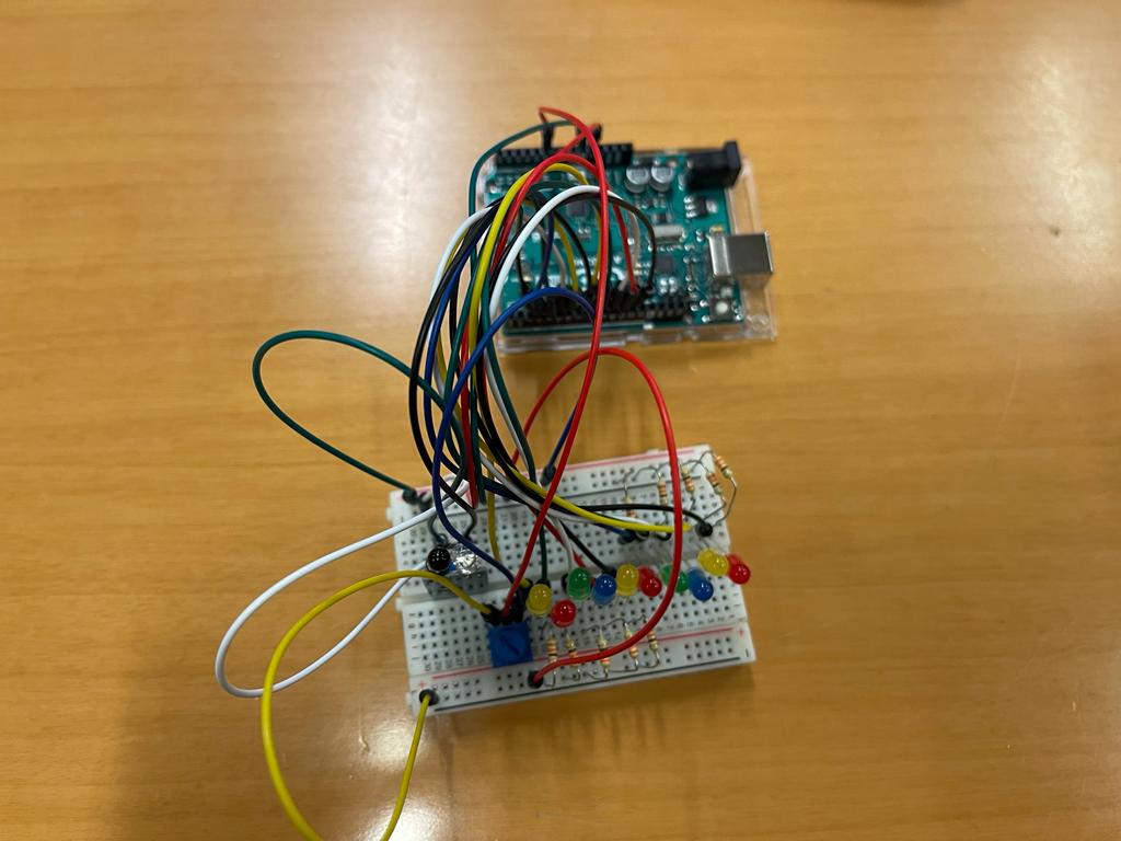
PROCEDURE:
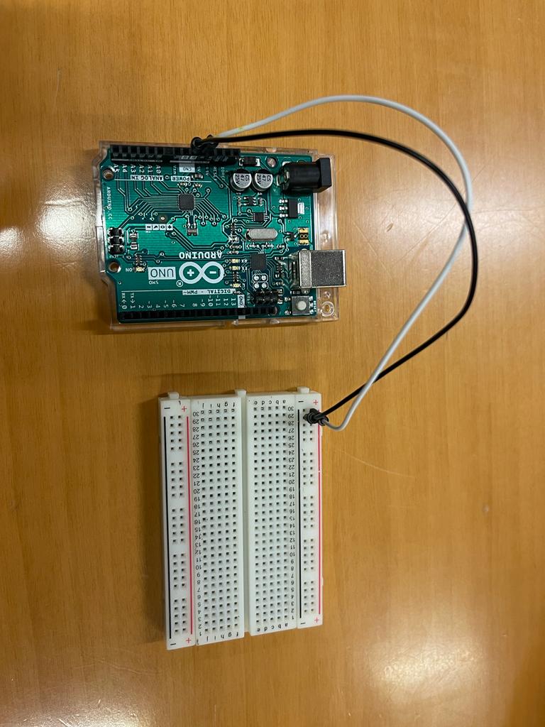
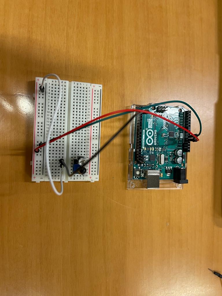
First, I used the Arduino board to power the + and – rails of the breadboard so that the entire circuit can use + and – from these rails whenever required in future connections. In the following image, a jumper wire goes into the +ve rail and the other goes into the -ve rail.
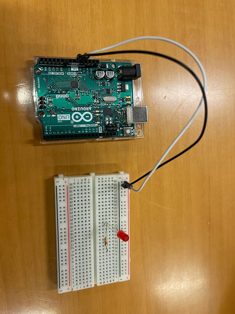
Having already connected the LED in the last assignment, I have quickly completed the following circuit and the anode of LED (longer leg) was connected to Arduino D7 and the resistor was connected to the ground rail as shown below.
I tested the simple LED circuit by uploading the following code and it have worked.
// C++ code

//it runs only once

void setup()
{
  //pinmode is used to configure pin number 7 as an output
  pinMode(7, OUTPUT);
}

// runs forever
void loop()
{
  //writing a logic high which equals 5 volt or 1 in binary
  //jumper wire connected to anode, LED switch on
  digitalWrite(7, HIGH);
  delay(1000); // Wait for 1000 millisecond(s)

  //writing a logic low which equals  0 in binary
  //jumper wire connected to anode, LED switch off
  digitalWrite(7, LOW);
  delay(1000); // Wait for 1000 millisecond(s)
}
The video shown below was the output !
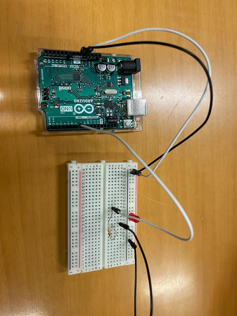
Next, I wanted to test the digital sensor with a single LED, so I have connected the sensor on breadboard and powered it with the onboard power rails. I connected the output of sensor to digital pin 7 which was configured as an input. Moreover , I have utilized the following code and the output was as shown in video below.
// C++ code


void setup()
{
  //pinmode is used to configure pin number 7 as an output
  pinMode(7, OUTPUT);
  //configuring 6 as input to read data from external switch/ sensor
  pinMode(6,INPUT);
}

void loop()
{
  //LED switch off

  if(digitalRead(6)==LOW)
  {
    // LED switch on
    digitalWrite(7, HIGH);
  }
  else
  {
    // LED switch off
    digitalWrite(7, LOW);
  }
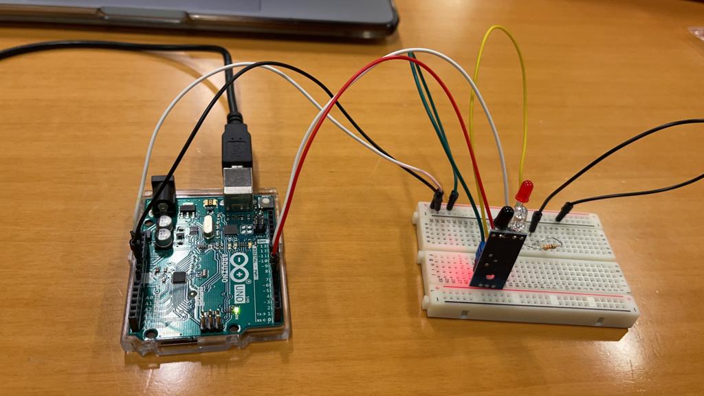
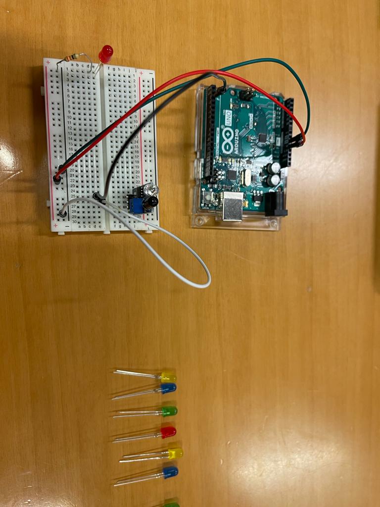
Then, I moved on to the connection of the digital proximity sensor with 5 LED’s. I removed the earlier LED and disconnected the sensor output pin. Now, only the power rails were connected to the respective pins as shown.
Next, I started to connect a single LED. All the other LED’s were kept ready to be placed on the breadboard.
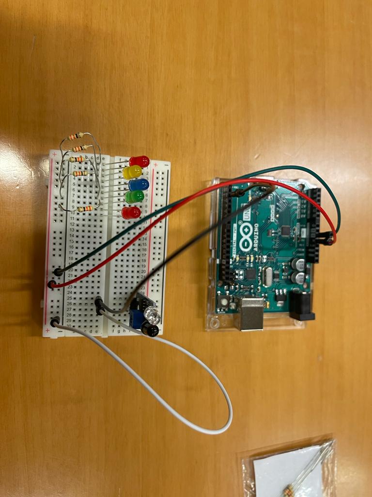
Then, all the 5 LEDs were connected with the resistors. I kept the colours different to get a nice colourful effect.
Moving forward, I connected all the LEDs and the digital sensor with Arduino and wrote a code to test all LEDs with my sensor. This way I was able to test all LEDs individually. The output video is shown.
// Shamma's code

// LED connected to 3,4,5,6,7 in arduino board
int gled = 3, b1led = 4, b2led = 5, yled = 6, rled = 7;

//sensor connected to pin 2 , the proximity sensor
int sensor = 2;

// initialize count variable to zero
int count = 0;

void setup()
{
  //All leds are being configured as an output and sensor is configured as an input because we read from it
  pinMode(gled, OUTPUT);pinMode(b1led, OUTPUT);
  pinMode(b2led, OUTPUT);pinMode(yled, OUTPUT);
  pinMode(rled, OUTPUT);
  pinMode(sensor,INPUT);

  //by default, I am switching all the leds off,
  //even if I remove those, code will work as my count is zero
  digitalWrite(gled,LOW);digitalWrite(b1led,LOW);
  digitalWrite(b2led,LOW);digitalWrite(yled,LOW);
  digitalWrite(rled,LOW);
}


void loop()
//reading if proximity sensor is low, then I will increment count variable by one

{
  //Once I place the hand, the count variable will switch from zero to 1,2,3,4,5,6
  //One is off, while next is on
  if(digitalRead(sensor)==LOW)
  {
    count = count + 1;

    //I use 5 LEDS, so I put 6 to restart the count
    if(count == 6)
    {
      count = 0;
    }
  }

// IF CONDITION for each LED on the mother board
  if(count == 0)
  {
    digitalWrite(gled,LOW);digitalWrite(b1led,LOW);
    digitalWrite(b2led,LOW);digitalWrite(yled,LOW);
    digitalWrite(rled,LOW);
  }
  else if(count == 1)
  {
    digitalWrite(gled,HIGH);digitalWrite(b1led,LOW);
    digitalWrite(b2led,LOW);digitalWrite(yled,LOW);
    digitalWrite(rled,LOW);
  }
  else if(count == 2)
  {
    digitalWrite(gled,LOW);digitalWrite(b1led,HIGH);
    digitalWrite(b2led,LOW);digitalWrite(yled,LOW);
    digitalWrite(rled,LOW);
  }
  else if(count == 3)
  {
    digitalWrite(gled,LOW);digitalWrite(b1led,LOW);
    digitalWrite(b2led,HIGH);digitalWrite(yled,LOW);
    digitalWrite(rled,LOW);
  }
  else if(count == 4)
  {
    digitalWrite(gled,LOW);digitalWrite(b1led,LOW);
    digitalWrite(b2led,LOW);digitalWrite(yled,HIGH);
    digitalWrite(rled,LOW);
  }
  else if(count == 5)
  {
    digitalWrite(gled,LOW);digitalWrite(b1led,LOW);
    digitalWrite(b2led,LOW);digitalWrite(yled,LOW);
    digitalWrite(rled,HIGH);
  }
  // once I place my hand, this delay will stop down the program
  delay(500);
}
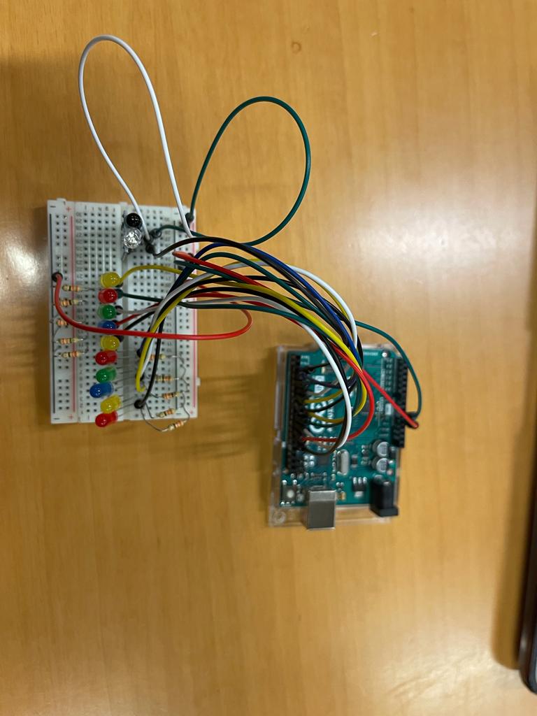
After successfully completing the digital sensor, I worked on analog sensor and chose potentiometer. So, another 5 LEDs were added which would be controlled via analog sensor.
Just to be double sure that all LEDs were connected properly, I wrote a small test LEDs code. This ensured that the wiring was properly done with no errors. The output was as following:
Finally, I added my analog sensor, the potentiometer in the circuit. It had 3 terminals out of which the corner ones were power rails and the middle one was the analog output which was connected to the analog input 0.
I wrote another small code to test only the analog sensor which turned the 5 LEDs dedicated for analog sensor one by one like shown.
// C++ code
//
int gled = 3, b1led = 4, b2led = 5, yled = 6, rled = 7;
//added the other 5 leds which will be used for my analog
int g2led = 8, b3led = 9, b4led = 10, y2led = 11, r2led = 12;
int digital_sensor = 2;
//declared the analog sensor
int analog_sensor = A0;
int count = 0;

void setup()
// all ten leds are configured as outputs
{
  pinMode(gled, OUTPUT);pinMode(b1led, OUTPUT);
  pinMode(b2led, OUTPUT);pinMode(yled, OUTPUT);
  pinMode(rled, OUTPUT);

  pinMode(digital_sensor,INPUT);

  pinMode(g2led, OUTPUT);pinMode(b3led, OUTPUT);
  pinMode(b4led, OUTPUT);pinMode(y2led, OUTPUT);
  pinMode(r2led, OUTPUT);

 // All 10 leds will be turned off

  digitalWrite(gled,LOW);digitalWrite(b1led,LOW);
  digitalWrite(b2led,LOW);digitalWrite(yled,LOW);
  digitalWrite(rled,LOW);

  digitalWrite(g2led,LOW);digitalWrite(b3led,LOW);
  digitalWrite(b4led,LOW);digitalWrite(y2led,LOW);
  digitalWrite(r2led,LOW);
}

void loop()
{
  // Analog Sensor Code
  // Reading the value from the analog sensor and storing it in the variable count
  int count = analogRead(analog_sensor);

// I divided 1024 by 5 as I have 5 leds and took the range from one switch to another
  if(count<10)
  {
    digitalWrite(g2led,LOW);digitalWrite(b3led,LOW);    digitalWrite(b4led,LOW);digitalWrite(y2led,LOW);    digitalWrite(r2led,LOW);
  }
  //
  else if(count>=10 && count<210)
  {
    digitalWrite(g2led,HIGH);digitalWrite(b3led,LOW);  digitalWrite(b4led,LOW);digitalWrite(y2led,LOW);    digitalWrite(r2led,LOW);
  }
  else if(count>=210 && count<410)
  {
    digitalWrite(g2led,HIGH);digitalWrite(b3led,HIGH);  digitalWrite(b4led,LOW);digitalWrite(y2led,LOW);    digitalWrite(r2led,LOW);
  }
  else if(count>=410 && count<610)
  {
    digitalWrite(g2led,HIGH);digitalWrite(b3led,HIGH);  digitalWrite(b4led,HIGH);digitalWrite(y2led,LOW);    digitalWrite(r2led,LOW);
  }
  else if(count>=610 && count<810)
  {
    digitalWrite(g2led,HIGH);digitalWrite(b3led,HIGH);  digitalWrite(b4led,HIGH);digitalWrite(y2led,HIGH);    digitalWrite(r2led,LOW);
  }
  else if(count>810)
  {
    digitalWrite(g2led,HIGH);digitalWrite(b3led,HIGH);  digitalWrite(b4led,HIGH);digitalWrite(y2led,HIGH);    digitalWrite(r2led,HIGH);
  }

//  // Digital Sensor Code
//
//  if(digitalRead(digital_sensor)==LOW)
//  {
//    count = count + 1;
//    if(count == 6)
//    {
//      count = 0;
//    }
//  }
//
//  if(count == 0)
//  {
//    digitalWrite(gled,LOW);digitalWrite(b1led,LOW);
//    digitalWrite(b2led,LOW);digitalWrite(yled,LOW);
//    digitalWrite(rled,LOW);
//  }
//  else if(count == 1)
//  {
//    digitalWrite(gled,HIGH);digitalWrite(b1led,LOW);
//    digitalWrite(b2led,LOW);digitalWrite(yled,LOW);
//    digitalWrite(rled,LOW);
//  }
//  else if(count == 2)
//  {
//    digitalWrite(gled,HIGH);digitalWrite(b1led,HIGH);
//    digitalWrite(b2led,LOW);digitalWrite(yled,LOW);
//    digitalWrite(rled,LOW);
//  }
//  else if(count == 3)
//  {
//    digitalWrite(gled,HIGH);digitalWrite(b1led,HIGH);
//    digitalWrite(b2led,HIGH);digitalWrite(yled,LOW);
//    digitalWrite(rled,LOW);
//  }
//  else if(count == 4)
//  {
//    digitalWrite(gled,HIGH);digitalWrite(b1led,HIGH);
//    digitalWrite(b2led,HIGH);digitalWrite(yled,HIGH);
//    digitalWrite(rled,LOW);
//  }
//  else if(count == 5)
//  {
//    digitalWrite(gled,HIGH);digitalWrite(b1led,HIGH);
//    digitalWrite(b2led,HIGH);digitalWrite(yled,HIGH);
//    digitalWrite(rled,HIGH);
//  }
  delay(500);
}
At last, I integrated the digital sensor and analog sensor code in one final code and I could control all 10 LEDs using different types of sensors.
// C++ code
// This is a combination of code 2 and 3 , both the proximity sensor and the analog which is the potentiometer
//Digital and analog sensor

int gled = 3, b1led = 4, b2led = 5, yled = 6, rled = 7;
int g2led = 8, b3led = 9, b4led = 10, y2led = 11, r2led = 12;
int digital_sensor = 2;
int analog_sensor = A0;
int count = 0,count2 = 0;

void setup()
{
  pinMode(gled, OUTPUT);pinMode(b1led, OUTPUT);  pinMode(b2led, OUTPUT);pinMode(yled, OUTPUT);  pinMode(rled, OUTPUT);
  pinMode(digital_sensor,INPUT_PULLUP);
  pinMode(g2led, OUTPUT);pinMode(b3led, OUTPUT);    pinMode(b4led, OUTPUT);pinMode(y2led, OUTPUT);  pinMode(r2led, OUTPUT);
  digitalWrite(gled,LOW);digitalWrite(b1led,LOW);  digitalWrite(b2led,LOW);digitalWrite(yled,LOW);  digitalWrite(rled,LOW);
  digitalWrite(g2led,LOW);digitalWrite(b3led,LOW);  digitalWrite(b4led,LOW);digitalWrite(y2led,LOW);  digitalWrite(r2led,LOW);
}

void loop()
{
  // Analog Sensor Code
  int count = analogRead(analog_sensor);

  if(count<10)
  {
    digitalWrite(g2led,LOW);digitalWrite(b3led,LOW);    digitalWrite(b4led,LOW);digitalWrite(y2led,LOW);    digitalWrite(r2led,LOW);
  }
  else if(count>=10 && count<210)
  {
    digitalWrite(g2led,HIGH);digitalWrite(b3led,LOW);  digitalWrite(b4led,LOW);digitalWrite(y2led,LOW);    digitalWrite(r2led,LOW);
  }
  else if(count>=210 && count<410)
  {
    digitalWrite(g2led,HIGH);digitalWrite(b3led,HIGH);  digitalWrite(b4led,LOW);digitalWrite(y2led,LOW);    digitalWrite(r2led,LOW);
  }
  else if(count>=410 && count<610)
  {
    digitalWrite(g2led,HIGH);digitalWrite(b3led,HIGH);  digitalWrite(b4led,HIGH);digitalWrite(y2led,LOW);    digitalWrite(r2led,LOW);
  }
  else if(count>=610 && count<810)
  {
    digitalWrite(g2led,HIGH);digitalWrite(b3led,HIGH);  digitalWrite(b4led,HIGH);digitalWrite(y2led,HIGH);    digitalWrite(r2led,LOW);
  }
  else if(count>810)
  {
    digitalWrite(g2led,HIGH);digitalWrite(b3led,HIGH);  digitalWrite(b4led,HIGH);digitalWrite(y2led,HIGH);    digitalWrite(r2led,HIGH);
  }

  // Digital Sensor Code

  if(digitalRead(digital_sensor)==LOW)
  {
    count2 = count2 + 1;
    if(count2 == 6)
    {
      count2 = 0;
    }
  }

  if(count2 == 0)
  {
    digitalWrite(gled,LOW);digitalWrite(b1led,LOW);
    digitalWrite(b2led,LOW);digitalWrite(yled,LOW);
    digitalWrite(rled,LOW);
  }
  else if(count2 == 1)
  {
    digitalWrite(gled,HIGH);digitalWrite(b1led,LOW);
    digitalWrite(b2led,LOW);digitalWrite(yled,LOW);
    digitalWrite(rled,LOW);
  }
  else if(count2 == 2)
  {
    digitalWrite(gled,HIGH);digitalWrite(b1led,HIGH);
    digitalWrite(b2led,LOW);digitalWrite(yled,LOW);
    digitalWrite(rled,LOW);
  }
  else if(count2 == 3)
  {
    digitalWrite(gled,HIGH);digitalWrite(b1led,HIGH);
    digitalWrite(b2led,HIGH);digitalWrite(yled,LOW);
    digitalWrite(rled,LOW);
  }
  else if(count2 == 4)
  {
    digitalWrite(gled,HIGH);digitalWrite(b1led,HIGH);
    digitalWrite(b2led,HIGH);digitalWrite(yled,HIGH);
    digitalWrite(rled,LOW);
  }
  else if(count2 == 5)
  {
    digitalWrite(gled,HIGH);digitalWrite(b1led,HIGH);
    digitalWrite(b2led,HIGH);digitalWrite(yled,HIGH);
    digitalWrite(rled,HIGH);
  }
  delay(500);
}
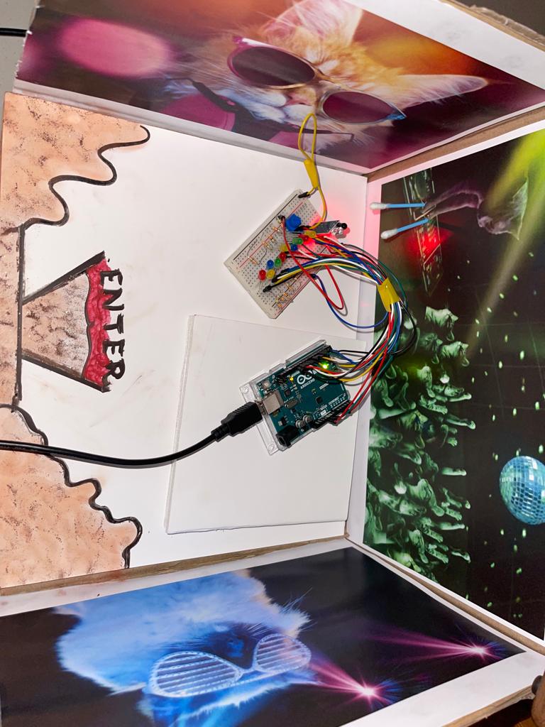
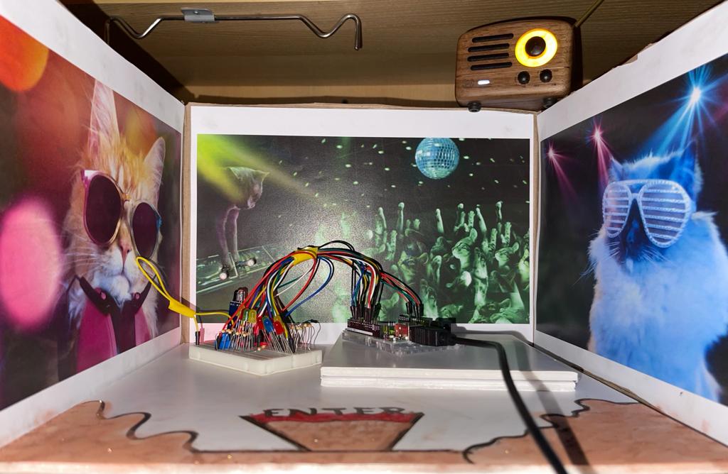
Just to add a little spice, I decided to cut down a cartoon box I found that is recycled and turn it into a space for cats to party. I did that by printing a couple of images, using a card board to give definition in terms of the party stage by adding a couple of card board together. Then, I used cotton bods as they will act as the cat paws which will trigger the proximity sensor when being moved on top of it. Later, I did not have any markers to draw the entrance of the party, so I used some makeup powders and eyeliner that I had, so excuse me for the mess. I also added a small radio I had on top of the box so I can run inside it a little fun cat song. At last, I placed the Arduino inside the cat space party to make the experience more real.
CONCLUSION:
The experience with this assignment has opened my eyes to the use of different sensors and how to interface them with Arduino. By being able to control LEDs using analog and digital sensors, although it’s a simple thing, it made me more enthusiastic about the more interesting applications that is to come.