Description / Mechanism
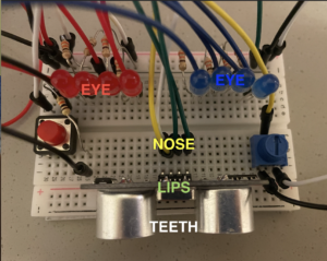
For this week’s assignment, I made a project that looks like a face of a robot, which has lights as its eyes, cables as nose and the distance sensor as mouth.
Normally, it looks straight at you, with the lights at the center of both sides on. If you turn the potentiometer left, the robot looks left, so the red lights are on. If you turn it right, the blue lights are on, showing that the robot is now looking right. If you move close to the robot’s face (mouth), it gets shy and closes its eyes, so the lights are all off.
If you press the button, the robot will enter into another state. Instead of looking at you, it starts processing data, so I have the delays between LEDs to show how data flows through. Then if you press again, it will go back to its original state.
Code
const int led1 = 2;
const int led2 = 3;
const int led3 = 4;
const int led4 = 5;
const int led5 = 6;
const int led6 = 7;
const int led7 = 8;
const int led8 = 9;
const int button = 10;
const int echo = 12;
const int trig = 13;
const int knob = A1;

int count = 0;
int ledState = LOW;
int buttonState1;
int buttonState2;
int de = 100;
bool off = false;

void setup() {
  // put your setup code here, to run once:
  Serial.begin(9600);
  pinMode(led1, OUTPUT);
  pinMode(led2, OUTPUT);
  pinMode(led3, OUTPUT);
  pinMode(led4, OUTPUT);
  pinMode(led5, OUTPUT);
  pinMode(led6, OUTPUT);
  pinMode(led7, OUTPUT);
  pinMode(led8, OUTPUT);

  pinMode(button, INPUT);
  pinMode(knob, INPUT);
  pinMode(trig, OUTPUT);
  pinMode(echo, INPUT);
  buttonState1 = digitalRead(button);
}

void loop() {
  buttonState2 =  digitalRead(button);
  if (buttonState2 != buttonState1) {
    if (buttonState2 == LOW) {
      count ++;
    }
  }
  buttonState1 = buttonState2;

  if (count%2 == 1) {
    ledState = HIGH;
  } else {
    ledState = LOW;
  }

  int knob_val = analogRead(knob);


  digitalWrite(trig, LOW);
  delayMicroseconds(2);
  digitalWrite(trig, HIGH);
  delayMicroseconds(2);
  digitalWrite(trig, LOW);

  int duration = pulseIn(echo, HIGH);
  int dist = duration/58.2;


  if (ledState == HIGH) {
    digitalWrite(led1, HIGH);
    delay(de);
    digitalWrite(led2, HIGH);
    delay(de);
    digitalWrite(led3, HIGH);
    delay(de);
    digitalWrite(led4, HIGH);
    delay(de);
    digitalWrite(led5, HIGH);
    delay(de);
    digitalWrite(led6, HIGH);
    delay(de);
    digitalWrite(led7, HIGH);
    delay(de);
    digitalWrite(led8, HIGH);

    digitalWrite(led1, LOW);
    delay(de);
    digitalWrite(led2, LOW);
    delay(de);
    digitalWrite(led3, LOW);
    delay(de);
    digitalWrite(led4, LOW);
    delay(de);
    digitalWrite(led5, LOW);
    delay(de);
    digitalWrite(led6, LOW);
    delay(de);
    digitalWrite(led7, LOW);
    delay(de);
    digitalWrite(led8, LOW);
  } else {
    int del;
    if (dist <= 10) {
      off = true;
    } else {
      off = false;
    }
    if (off) {
      digitalWrite(led1, LOW);
      digitalWrite(led4, LOW);
      digitalWrite(led5, LOW);
      digitalWrite(led8, LOW);
      digitalWrite(led2, LOW);
      digitalWrite(led3, LOW);
      digitalWrite(led6, LOW);
      digitalWrite(led7, LOW);
    } else {

    if (knob_val>300 and knob_val<630) {
      digitalWrite(led1, LOW);
      digitalWrite(led4, LOW);
      digitalWrite(led5, LOW);
      digitalWrite(led8, LOW);
      digitalWrite(led2, HIGH);
      digitalWrite(led3, HIGH);
      digitalWrite(led6, HIGH);
      digitalWrite(led7, HIGH);
    }
    if (knob_val<=300) {
      digitalWrite(led1, HIGH);
      digitalWrite(led4, HIGH);
      digitalWrite(led5, LOW);
      digitalWrite(led8, LOW);
      digitalWrite(led2, HIGH);
      digitalWrite(led3, HIGH);
      digitalWrite(led6, LOW);
      digitalWrite(led7, LOW);
    }
    if (knob_val>=630) {
      digitalWrite(led1, LOW);
      digitalWrite(led4, LOW);
      digitalWrite(led5, HIGH);
      digitalWrite(led8, HIGH);
      digitalWrite(led2, LOW);
      digitalWrite(led3, LOW);
      digitalWrite(led6, HIGH);
      digitalWrite(led7, HIGH);
    }
    }
  }


}
Challenges
Initially, instead of the distance sensor, I was going to use the LDR sensor as the robot’s nose. However, the light in the dorm was not suitable for it and the output of the LDR value was quite random. I couldn’t figure out how to use the photo cell properly, so I changed it to the distance sensor, which is more reliable 🙂 Then I readjusted the position and found that the cables could be the nose!
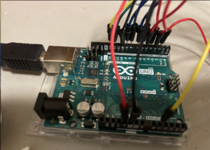
The challenge I encountered was how to arrange the elements to create a correct circuit. Since I had many parts on the board, I needed to be careful not to overlap the positions for power/ground, so that they don’t touch each other to form another circuit. Thanks to Professor Aaron, I successfully connected the button and also the distance sensor.
The code part was not so challenging, but it took me some time to figure out the logics. The order of the conditions in the codes was difficult to sort out.
Overall, I think I have learned a lot from this project and have a better understanding of how the circuits work, especially how the sensors work.


