Description:
This project consisted of using creativity to implement a digital and an analog sensor in the Arduino to represent something.
Idea:
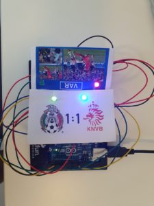
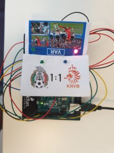
For this assignment, I decided to simulate a VAR system in soccer. The VAR stands for Video Assistance Referee and it is a system in soccer that checks for the repetition of a play. The main referee in the game can request a VAR check if he/she is not sure of a play. Humans are not perfect and referees make mistakes; therefore it is essential to implement the VAR in soccer games. However, this system was created recently. I remember a game in the World Cup 2014 where Mexico faced the Netherlands. Mexico lost the game 2-1 because of a play that conceded a penalty to the Netherlands. However, several repetitions demonstrated that a penalty should not have been awarded. If VAR had existed in this game, maybe the results would have been different.
Challenges:
For this project, the main challenge was understanding and working with Arduino code. Since I am not familiar with the functions in Arduino I faced several challenges trying to figure out what was wrong with my code. Also, another challenge was making sure everything in the Arduino was connected properly. I spent a lot of time figuring out why my code didn’t work and ended up realizing I had misplaced the wires when connecting the knob. Also checking for wires is a challenge because there is a lot of content in the breadboard and Arduino that it gets unorganized and confusing.
Process:
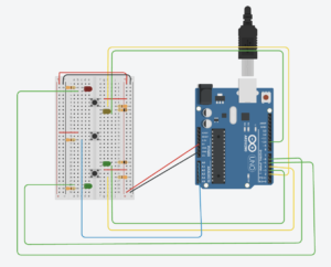
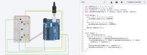
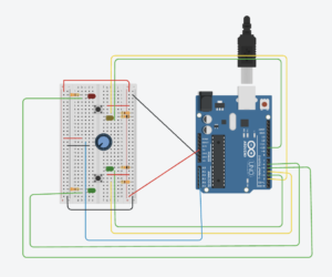
I first started using TinkerCad to simulate my project. First I connected what was necessary, then I replicated this image into the real breadboard and Arduino. After making sure everything was connected as planned I started coding. First, I wanted to use three buttons and one knob. My idea was to implement a button with the knob so that the knob would be working only if the button was pressed and would stop working if the button was pressed once again. After spending some hour trying to figure this out, I gave up and decided to use only one knob. For this reason, I had to use only one of the LEDs(red one) in the VAR which is controlled by the knob. After coding everything, I tried the code on the model I had on TinkerCad. If something was not working, then I checked my code and my model until the outcome gave me something I wanted. When I finally completed the model in TinkerCad I implemented the same exact thing on my breadboard and Arduino Code. Finally, I also edited and printed some images to represent the soccer match.
Conclusion:
Overall I had a lot of fun with this project. I think this assignment was very different from previous assignments because we actually got to work with something physical. Although I failed to accomplish my initial plan, I am proud of the final outcome. I really enjoyed working on this project, especially the part where I get to connect things in the Arduino and Breadboard. I think I have learned a lot and I have a better idea of how several concepts work in the Arduino.
int ledPin[4] = { 10, 3, 5, 6};
int buttonPin[3] = {2, 4, 12};
bool onOff[4] = {false, false, false, false};
bool prevButtonState[3] = {false, false, false};
int scoreMex = 0;
int scoreNed = 0;
int knobPin = A0;
int knobState = false;

void setup() {
  for( int i = 0; i < 4; i++){
    pinMode(ledPin[i], OUTPUT);
  }
  for( int i = 0; i < 3; i++){
    pinMode(buttonPin[i], OUTPUT);
  }
  pinMode(knobPin, INPUT);
  Serial.begin(9600);
}

void loop() {
  bool buttonState[3];
  int knobValue = analogRead(knobPin);
  int mappedValue = map(knobValue, 0, 1023, 0, 255);
  for(int i = 0; i < 2; i++){
    buttonState[i] = digitalRead(buttonPin[i]);
    if(buttonState[i] == HIGH && prevButtonState[i] == LOW){
      onOff[i] = !onOff[i];
      if( i == 0 && onOff[0] == true){
        scoreNed++;
        Serial.print("Netherlands Score");
      }
      if( i == 1 && onOff[1] == true){
        scoreMex++;
        Serial.print("Mexico Score");
      }
    }
    Serial.println("Netherlands\tMexico");
    Serial.println(scoreNed + "\t:\t" + scoreMex);
    digitalWrite(ledPin[i], onOff[i]);
    prevButtonState[i] = buttonState[i];
  }
  analogWrite(ledPin[3], mappedValue);

}

