LED lightshow!

I love throwing dance parties (in non-COVID times of course). One of the things on my “To build” dream list is an LED cube synchronized to music.

Sort of like this:

But, alas, senior year is not the most compatible with the desire to just build the things I want to build.

Thus, I decided to use this project to get a bit closer to that LED cube. I probably could have just built the LED cube for this project but I lack access to a laser cutter right now which I would want to use to organize the cube.

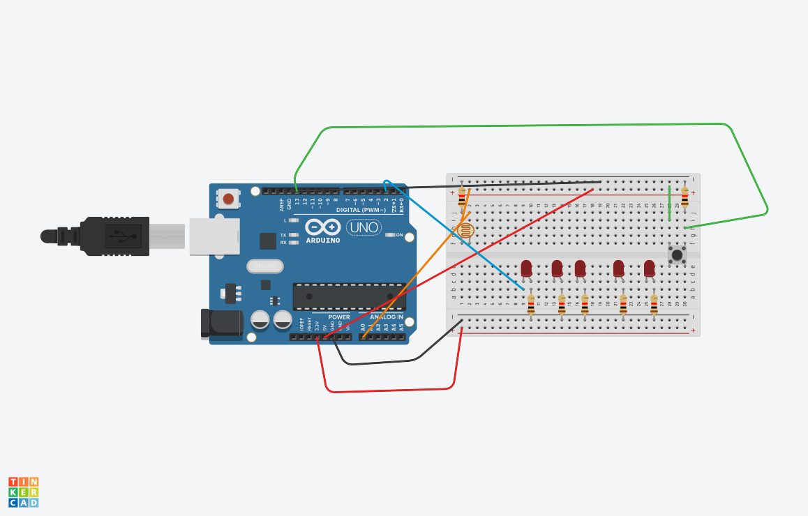
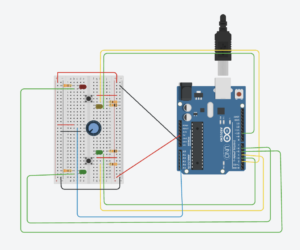
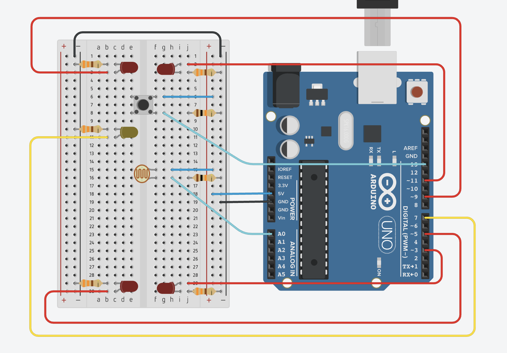
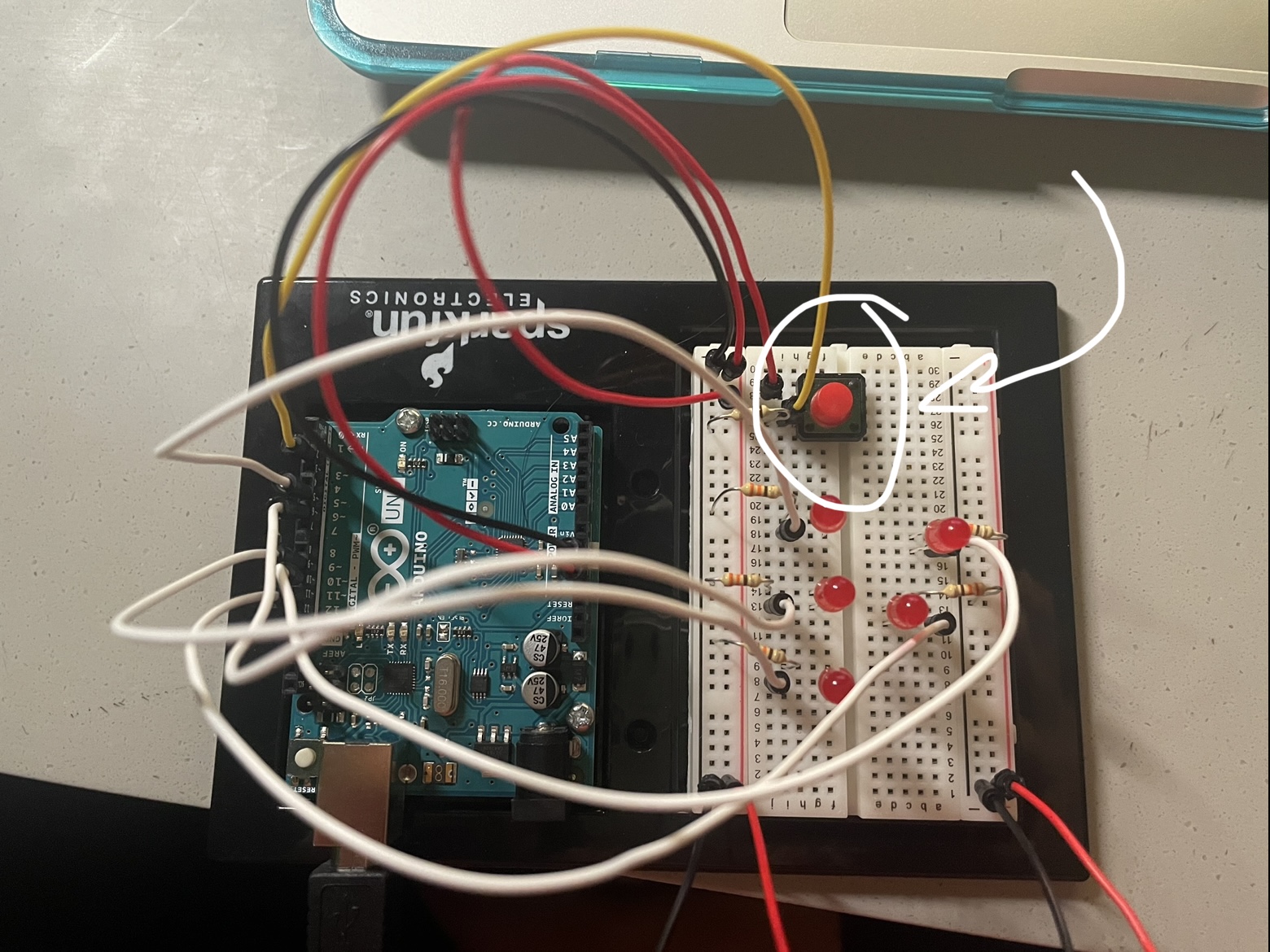
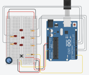
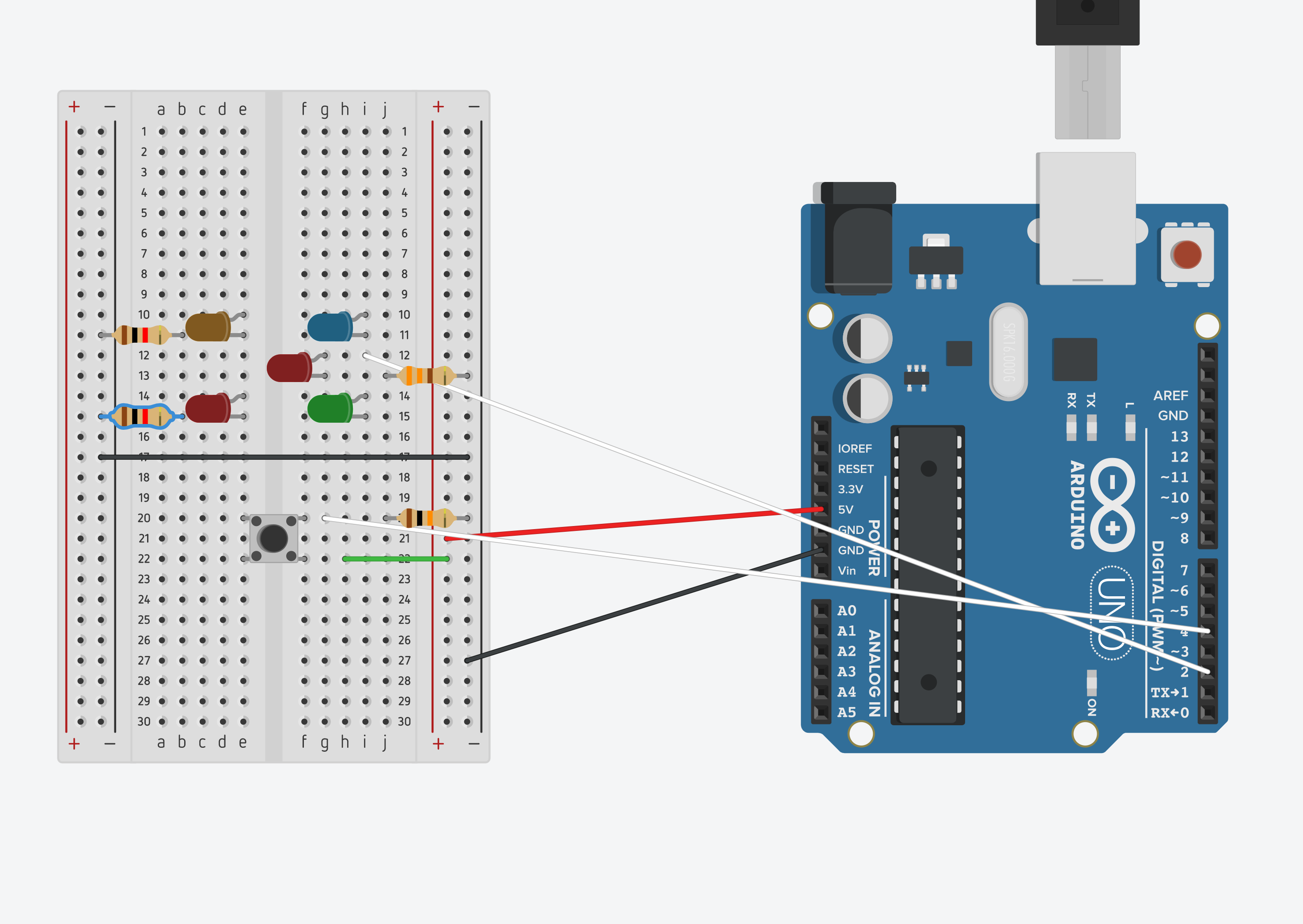
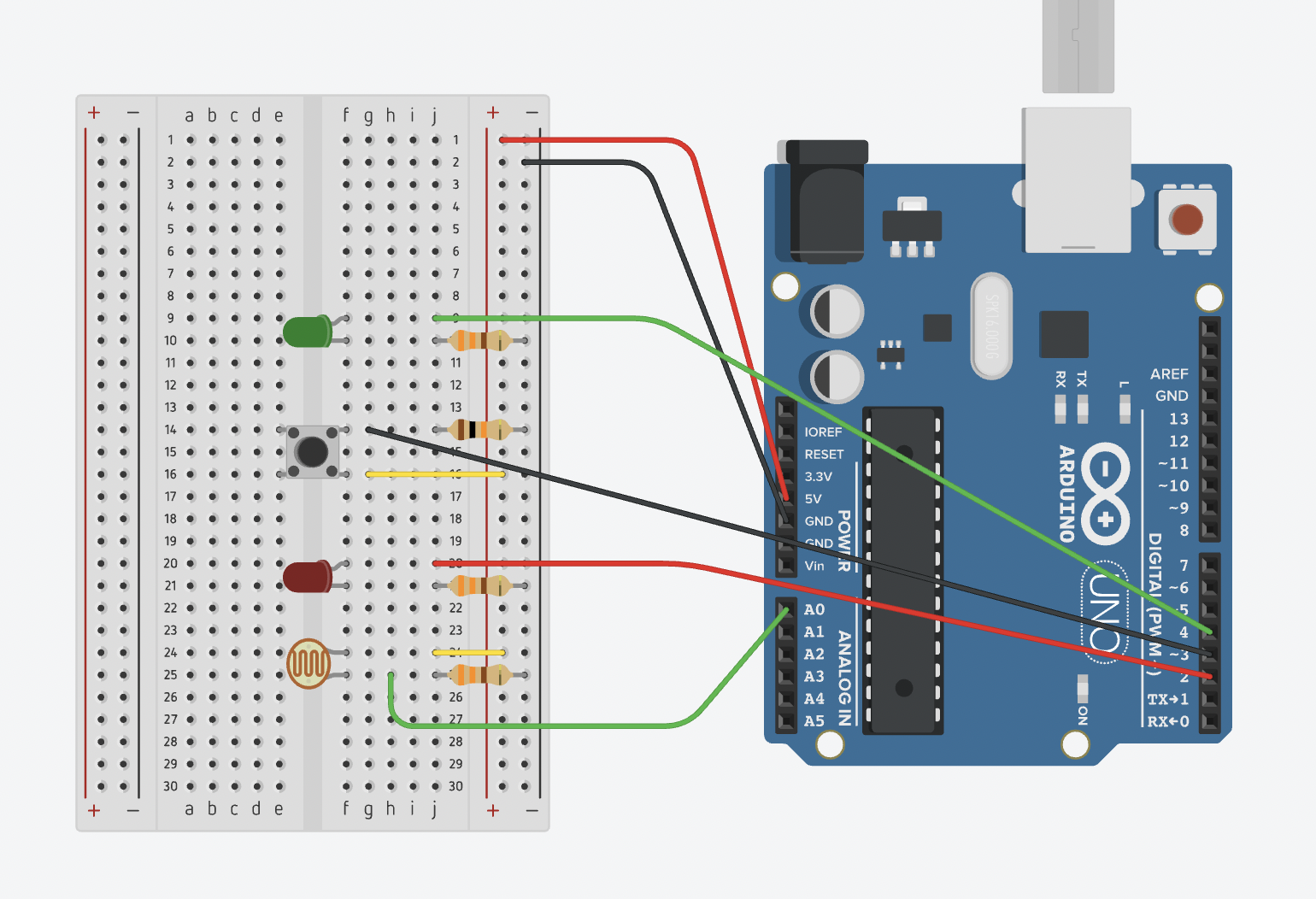
I first built a simple led sequencer with the speed controlled by the potentiometer and a button to turn it on and off.

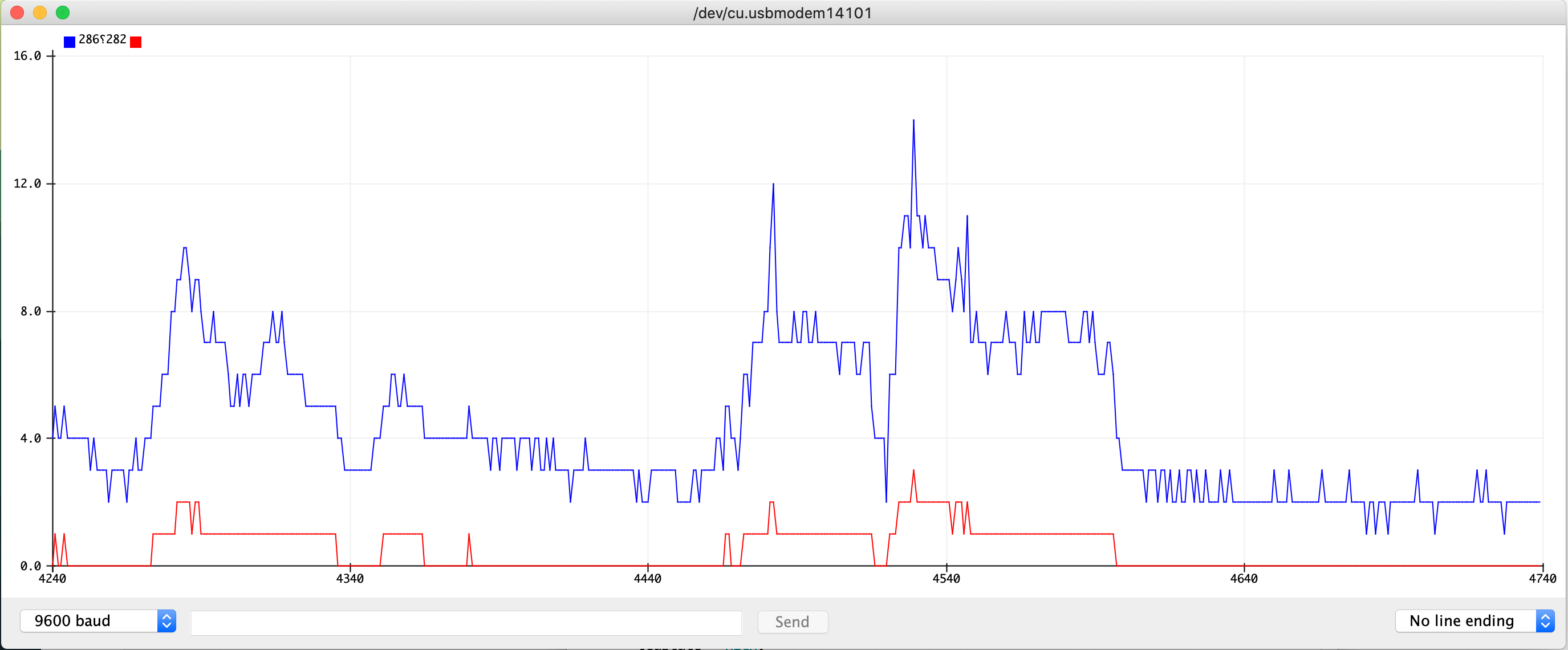
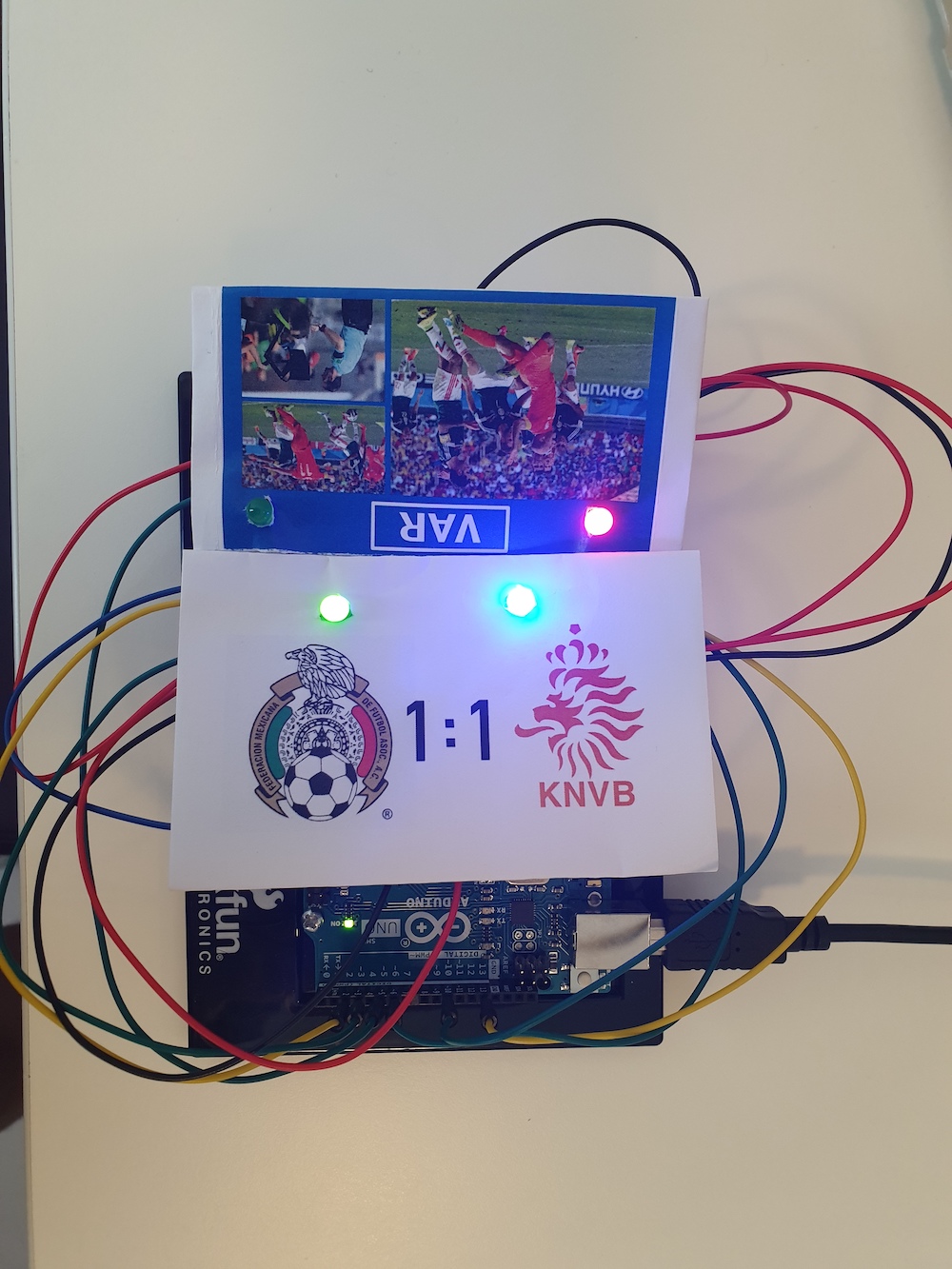
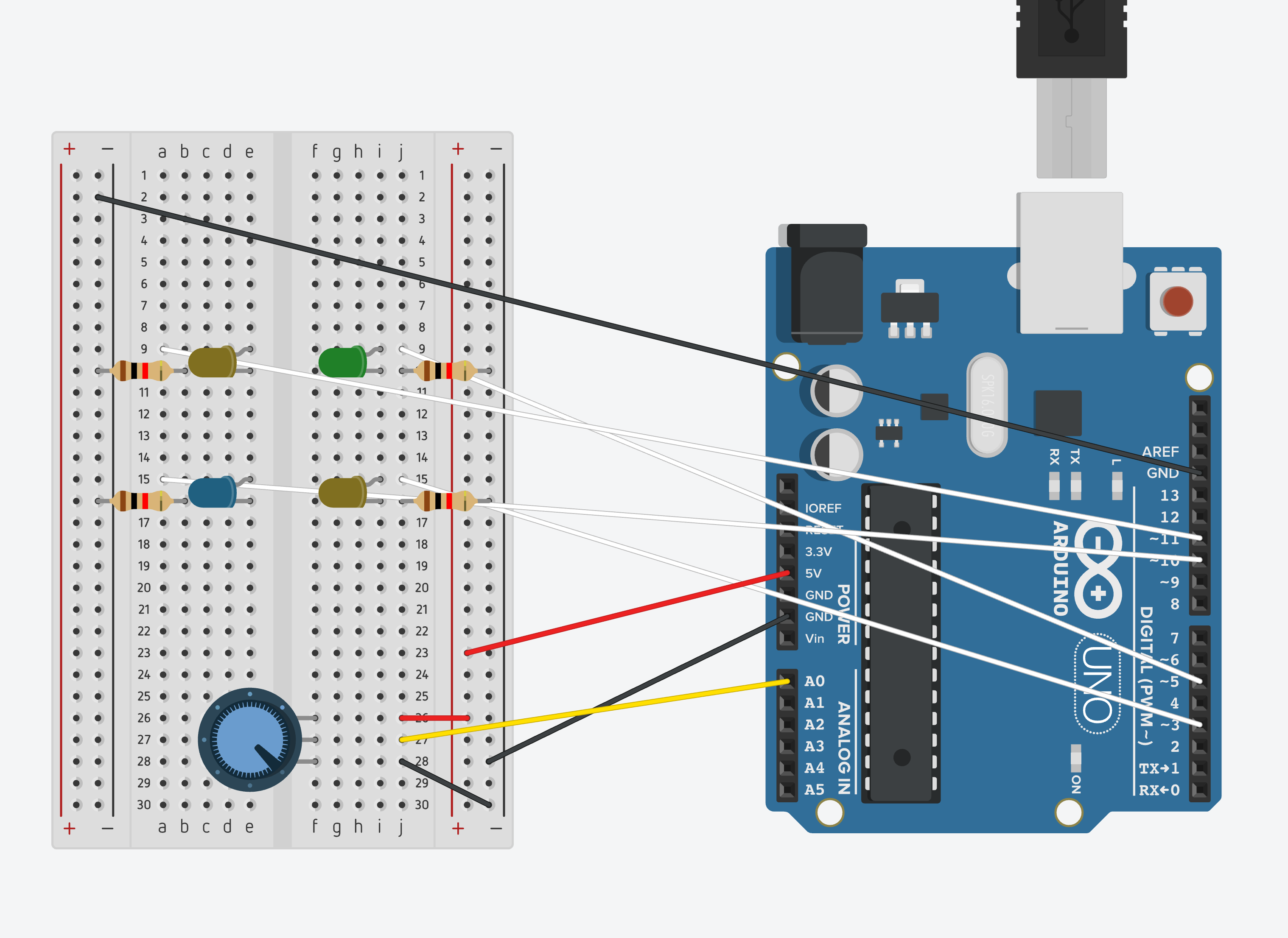
Then, I moved to creating the synchronization with music. The potentiometer controls the brightness of the pins with PWM…I would have liked to be able to control the brightness of all of them but was limited by the pin capacity on the arduino uno. The digital write uses the minim processing library to find attributes of the song playing and turn on certain LEDs accordingly.


EDIT:

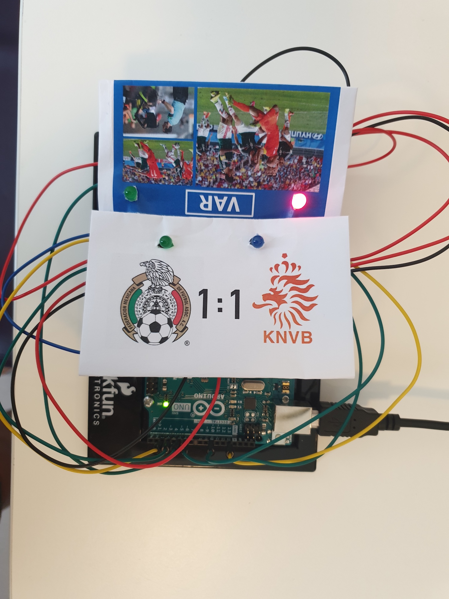
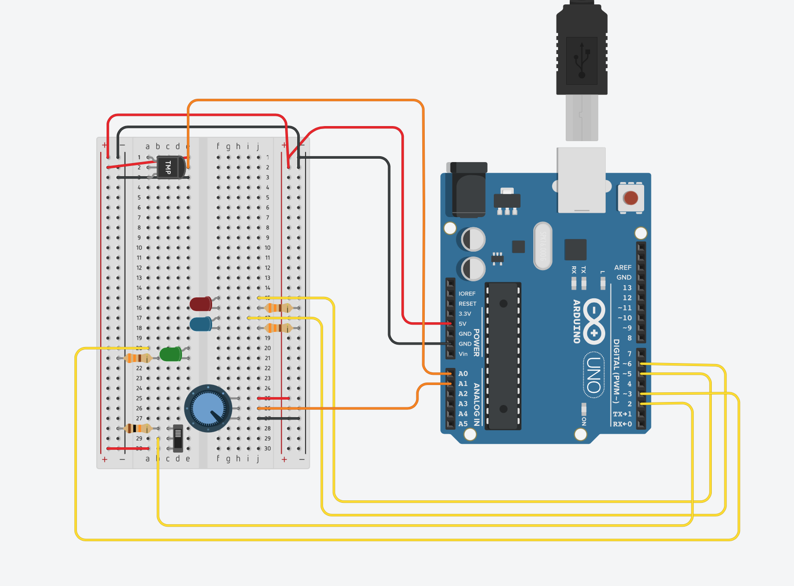
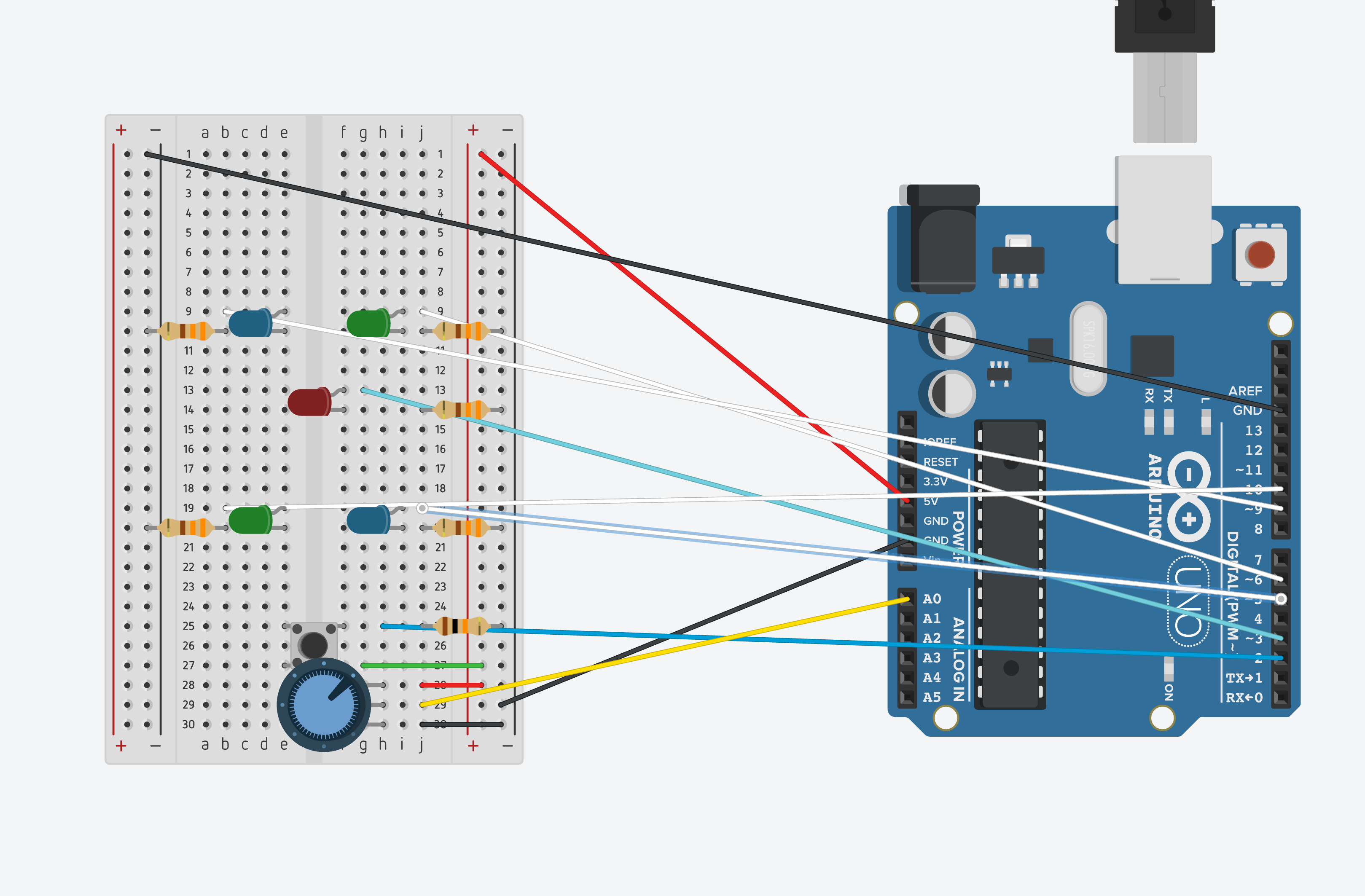
I realize it is difficult to see the effects of the potentiometer so I adjusted my circuit and code so that there are only 6 LEDs that are ALL connected to PWM pins.

My code is based on this instructable. I also relied on the method documentation in the Arduino for Processing library here. 

One difficult thing I encountered was differing datatypes for inputs/outputs of functions in the Arduino library in processing versus what I did when coding in the Arduino IDE.

Part 1 code:

int led[] = {2,3,4,5,6,7,8,9};
int buttonPin = 12;
int analogPin = A0;
bool onOff = false;
bool prevState = false;
int val = 0;

void setup() {
  for (int i = 0; i < sizeof(led); i++) {
    pinMode(led[i], OUTPUT);
  }
  pinMode(analogPin, INPUT);

  Serial.begin(9600);

}

void loop() {
  bool buttonState = digitalRead(buttonPin);
  Serial.println(buttonState);
  int pot = analogRead(analogPin);
  val = map(pot, 0, 1023, 0, 500);

  if (buttonState == HIGH && prevState == LOW) {
    onOff = !onOff;
  }
  for (int i = 0; i < sizeof(led); i++) {
    digitalWrite(led[i], onOff);
    delay(val);  
  }
  if (onOff) {
    for (int i = 0; i < sizeof(led); i++) {
      digitalWrite(led[i], !onOff);
      delay(val);  
    }
  }

  prevState = buttonState;

}

LED synchronization with music:

import processing.sound.*;
import processing.serial.*;
import ddf.minim.*;
import ddf.minim.analysis.*;
import cc.arduino.*;

Minim minim;
AudioPlayer song;
BeatDetect beat;
BeatListener bl;
Arduino arduino;
//the pin numbers I'm using
int led[] = {2,3,4,5,6,7,8,9};
int buttonPin = 12;
int analogPin = 0;
boolean onOff = false;
int prevState = 0;
float val = 0;

//based on the instructable https://www.instructables.com/How-to-Make-LEDs-Flash-to-Music-with-an-Arduino/
//kick is the bass drum
//snare is the higher pitch component
//hat (hi-hat) is the cymbal-like beat


void setup() {
  size(100,100);
  
  minim = new Minim(this);
  //57600 is the speed of connection -- this appears to be a standard value used
  //[2] is the port that I am using
  arduino = new Arduino(this, Arduino.list()[2], 57600);

  song = minim.loadFile("redbone.mp3", 2048);
  song.play();
 //BeatDetect is a class in the minim library that will allow me to use built-in methods to detect the types of beats
  beat = new BeatDetect(song.bufferSize(), song.sampleRate());
 //the algorithm will wait for 100 milliseconds before detecting another beat
  beat.setSensitivity(100);  
  //used BeatListener class from instructable
  bl = new BeatListener(beat, song);  
 //set up pins for output
   for (int i = 0; i < led.length; i++) {
    arduino.pinMode(led[i], Arduino.OUTPUT);
  }
  //analog pin for potentiometer
  arduino.pinMode(analogPin, Arduino.INPUT);
}

void draw() {
  background(0);
  //this turned out to take an integer value. originally tried to make it take a boolean instead.
  int buttonState = arduino.digitalRead(buttonPin);
  println(buttonState);
  
  if (buttonState == 1 && prevState == 0) {
    onOff = !onOff;
  }
  println(onOff);
  //gets value from potentiometer
  float pot = arduino.analogRead(analogPin);
  println(pot);
  val = map(pot, 0, 1023, 0, 255);

  //if(onOff) {
  //uses beat detect method to detect for bass
  //digitally writes to specific LEDs
  //analog writes brightness of pot to pin 3
  if(beat.isKick()) {
      arduino.digitalWrite(led[0], Arduino.HIGH);   // set the LED on
      arduino.analogWrite(led[1], int(val));   // set the LED on
      arduino.digitalWrite(led[6], Arduino.HIGH);   // set the LED on
      arduino.digitalWrite(led[7], Arduino.HIGH);   // set the LED on

  }
  //uses beat detect method to detect for snare
  //digitally writes to LED pins 4 and 7
  if(beat.isSnare()) {
      arduino.digitalWrite(led[2], Arduino.HIGH);   // set the LED on
            arduino.digitalWrite(led[5], Arduino.HIGH);   // set the LED on
  }
    //uses beat detect method to detect for cymbal
  //analog writes to LED pins 5 and 6 depending on pot brightness
  if(beat.isHat()) {
      arduino.analogWrite(led[3], int(val));   // set the LED on
            arduino.analogWrite(led[4], int(val));   // set the LED on

  }
  //}
for (int i = 0; i < led.length; i++) {
    arduino.digitalWrite(led[i], Arduino.LOW);   // set the LED off
  }
            arduino.analogWrite(led[1], 0);   
            arduino.analogWrite(led[3], 0);   
            arduino.analogWrite(led[4], 0); 
  prevState = buttonState;

}

void stop() {
  song.close();
  minim.stop();
  super.stop();
}


Happy Birthday assignment


The aim of this week assignment  is to use one digital and one analog input. So, the whole story is about birthday cake. To switch on the leds you need to press the button(  digital input ),  after  you pressed the button they automatically start to turn on one after another. To “blow” on the candles i used photoresistor. You can use your finger or something else to close it and turn the leds off.


Scheme:

Picture:


Last version:

code:

int led1 = 2;
int led2 = 3;
int led3 = 4;
int led4 = 5;
int led5 = 6;
int led6 = 7;
int led7 = 8;
int led8 = 9;
int a;
int t1 = 600;
bool v;
int vpin = A0;
int buttonPin = 13;


void setup() {
  pinMode(led1, OUTPUT);
  pinMode(led2, OUTPUT);
  pinMode(led3, OUTPUT);
  pinMode(led4, OUTPUT);
  pinMode(led5, OUTPUT);
  pinMode(led6, OUTPUT);
  pinMode(led7, OUTPUT);
  pinMode(buttonPin, INPUT);
  Serial.begin(9600);

}

void loop() {
  int currentButtonState = digitalRead(buttonPin);

  if (currentButtonState == HIGH){
    
    for(int i=2; i<9; i++){
      
        digitalWrite(i, HIGH);
        delay(t1);
        digitalWrite(i+1, HIGH);
        delay(t1);
        digitalWrite(i+2, HIGH);
        delay(t1);
        a = 2;
        }
  }

  if  (a == 2) {
  
      int Value = analogRead(vpin);
      int mappedValue = map(Value, 10, 100, 0, 255);
      
      for(int i=2; i<9; i++){
       analogWrite(i, mappedValue);
      }

 }
}


Digital input and Analog input

For this week’s assignment, we are asked to use at least one analog input to control one LED and at least one digital input to control one LED. I haven’t added the sketch yet so I am going to come back and add that creative element later!

I had fun with the line graph displaying the knobValue before and after being mapped. I made the graph curve by rotating the potentiometer. Below are the graph and the video of that:

Testing the button (digital input) and the potentiometer (analog input):


This is the code (how to make it color-coded though?) (updated: oh! it is color-coded in the post but not right in the editing space)

const int ledPinYellow = 3;
const int ledPinGreen = 7;
const int ledPinBlue = 12;
const int buttonPin = 2; 
int knobPin = A0;
int ledState = LOW;
int prevButtonState = LOW;

void setup() {
  pinMode(ledPinYellow, OUTPUT);
  pinMode(ledPinGreen, OUTPUT);
  pinMode(ledPinBlue, OUTPUT);
  pinMode(buttonPin, INPUT);
  //pinMode(A0, INPUT);

  Serial.begin(9600);
}

void loop() {
  int knobValue = analogRead(knobPin);
  int mappedValue = map(knobValue, 0, 1023, 0, 255);
  Serial.print(knobValue); 
  Serial.print("    ");
  Serial.println(mappedValue);

  analogWrite(ledPinYellow, mappedValue);


  int currentButtonState = digitalRead(buttonPin);
 
  if (currentButtonState == HIGH && prevButtonState == LOW) {
      // flip the LED state
      if (ledState == HIGH){
        ledState = LOW;
      } else if (ledState == LOW){
        ledState = HIGH;
      }
  }
  // if you want to print out the LED state
  // Serial.print(ledState);
 
  digitalWrite(ledPinGreen, ledState);
  digitalWrite(ledPinBlue, !ledState);
 
  //we need to remember the state of our button for the next time through LOOP
  prevButtonState = currentButtonState;
}


Week 9 : Digital and Analog

Description:

This project consisted of using creativity to implement a digital and an analog sensor in the Arduino to represent something.

Idea:

For this assignment, I decided to simulate a VAR system in soccer. The VAR stands for Video Assistance Referee and it is a system in soccer that checks for the repetition of a play. The main referee in the game can request a VAR check if he/she is not sure of a play. Humans are not perfect and referees make mistakes; therefore it is essential to implement the VAR in soccer games. However, this system was created recently. I remember a game in the World Cup 2014 where Mexico faced the Netherlands. Mexico lost the game 2-1 because of a play that conceded a penalty to the Netherlands. However, several repetitions demonstrated that a penalty should not have been awarded. If VAR had existed in this game, maybe the results would have been different.

Challenges:

For this project, the main challenge was understanding and working with Arduino code. Since I am not familiar with the functions in Arduino I faced several challenges trying to figure out what was wrong with my code. Also, another challenge was making sure everything in the Arduino was connected properly. I spent a lot of time figuring out why my code didn’t work and ended up realizing I had misplaced the wires when connecting the knob. Also checking for wires is a challenge because there is a lot of content in the breadboard and Arduino that it gets unorganized and confusing.

Process:

I first started using TinkerCad to simulate my project. First I connected what was necessary, then I replicated this image into the real breadboard and Arduino. After making sure everything was connected as planned I started coding. First, I wanted to use three buttons and one knob. My idea was to implement a button with the knob so that the knob would be working only if the button was pressed and would stop working if the button was pressed once again. After spending some hour trying to figure this out, I gave up and decided to use only one knob. For this reason, I had to use only one of the LEDs(red one) in the VAR which is controlled by the knob. After coding everything, I tried the code on the model I had on TinkerCad. If something was not working, then I checked my code and my model until the outcome gave me something I wanted. When I finally completed the model in TinkerCad I implemented the same exact thing on my breadboard and Arduino Code. Finally, I also edited and printed some images to represent the soccer match.


Conclusion:

Overall I had a lot of fun with this project. I think this assignment was very different from previous assignments because we actually got to work with something physical. Although I failed to accomplish my initial plan, I am proud of the final outcome. I really enjoyed working on this project, especially the part where I get to connect things in the Arduino and Breadboard. I think I have learned a lot and I have a better idea of how several concepts work in the Arduino.

int ledPin[4] = { 10, 3, 5, 6};
int buttonPin[3] = {2, 4, 12}; 
bool onOff[4] = {false, false, false, false};
bool prevButtonState[3] = {false, false, false};
int scoreMex = 0;
int scoreNed = 0;
int knobPin = A0;
int knobState = false;

void setup() {
  for( int i = 0; i < 4; i++){
    pinMode(ledPin[i], OUTPUT);
  }
  for( int i = 0; i < 3; i++){
    pinMode(buttonPin[i], OUTPUT);
  }
  pinMode(knobPin, INPUT);
  Serial.begin(9600);
}

void loop() {
  bool buttonState[3];
  int knobValue = analogRead(knobPin);
  int mappedValue = map(knobValue, 0, 1023, 0, 255);
  for(int i = 0; i < 2; i++){
    buttonState[i] = digitalRead(buttonPin[i]);
    if(buttonState[i] == HIGH && prevButtonState[i] == LOW){
      onOff[i] = !onOff[i];
      if( i == 0 && onOff[0] == true){
        scoreNed++;
        Serial.print("Netherlands Score");
      }
      if( i == 1 && onOff[1] == true){
        scoreMex++;
        Serial.print("Mexico Score");
      }
    }
    Serial.println("Netherlands\tMexico");
    Serial.println(scoreNed + "\t:\t" + scoreMex);
    digitalWrite(ledPin[i], onOff[i]);
    prevButtonState[i] = buttonState[i];
  }
  analogWrite(ledPin[3], mappedValue);
                      
}

Week 9 Assignment: Thermostat

Idea:

This week our task was to take digital and analog inputs, and light up LED lights with both digital and analog outputs. My goal was to make something similar to the thermostat on your wall. I wanted a power button, and a dial where you could turn up or down the temperature. I would then light up LED’s to show this working as if the heater or AC was turning on.

Implementation:

Digital Input: I started off using the button setup that we tried in class but decided it would be nicer if I used a switch. I found that a switch was wired very similarly to the button but was always in a 0 or 1 state. This made the code very easy as it did not require and saving of the previous state.

Analog Input: I needed two inputs here, the target temperature that the user wants which utilized a dial in the form of the potentiometer, as well as the room temperature which I tried using the included thermometer to implement. I found the wiring schematics online (short circuited it once by setting it up backwards), and managed to get analog outputs from it. The tricky part was converting from the analog input to degrees. I found that you could convert the analog input value into volts. The thermometer worked at a 10mV per degree linear ratio so I was able to convert it quite easily with the preset offset of 500mV from there. I checked the Serial.write value with my room thermostat and both matched.

Digital Output: The most basic part of my circuit was to light up a green power button if the system was on. I just wrote to a green LED high when the switch was on and low when it was off.

Analog Output: To light up the appropriate LED’s to represent the heater or AC turning on, I had to first get a target temperature from the potentiometer and compare that to the room temperature. If the room was warmer than the target I would light up the blue LED as if AC was turning on, and the red if the opposite was true to simulate the heater. I also lit up the LED’s stronger when the room temperature was further from the target temperature.


Results:

Here is a demo where I adjust the potentiometer to change the target temperature, as well as turn the system on and off with the switch.

Here is an example where I apply heat to the thermometer. This causes the system to think that the room is warm and you can see the AC light turn on. As it gets warmer the AC light gets brighter. (Headphone users beware)


Circuit: 


Code:

//Pins
const int tempPin = A0;
const int knobPin = A1;
const int switchPin = 2;
const int green = 3;
const int red = 5;
const int blue = 6;


bool on = false;
float temp; //What is the current temp from thermometer reading
float target; //Based on potentiometer what is the desired temperature

void setup() {
  //Start console comunication
  Serial.begin(9600);

  //Set pin modes
  pinMode(green, OUTPUT);
  pinMode(red, OUTPUT);
  pinMode(blue, OUTPUT);
  pinMode(switchPin, INPUT);

  //Set on off initial value
  on = digitalRead(switchPin);
}

void loop() {
  //Read in temperature value and convert it to celcius from analog in
  temp = (((analogRead(tempPin) * 5.0) / 1024) - 0.5) * 100;  //Convert from reading to mV to celcius with a 10mv per degree rating
  on = digitalRead(switchPin);

  //If on turn on lights
  if (on) {
    //Turn power (green light) on
    digitalWrite(green, HIGH);

    //Get the target temp from the potentiometer should be a value between 15 and 27, 21 is standard in the middle value
    target = map(analogRead(knobPin), 0, 1023, 15.0, 27.0);

    float difference = abs(map(temp - target, 0, 7, 0, 100)); //How far off the target value is it?, mapped to a value from 0 to 100 for an led to take
    //If hotter turn on red light up to 100 (so dimness is more clear)
    Serial.println(difference);
    if (temp - target < 0) {
      analogWrite(red, difference);
      analogWrite(blue, 0);
    }
    //Cooler than target
    else if (temp - target > 0) {
      analogWrite(red, 0);
      analogWrite(blue, difference);
    }
    //By some chance equal
    else {
      analogWrite(red, 0);
      analogWrite(blue, 0);
    }

  }
  else {
    //Turn power (green light) off
    digitalWrite(green, LOW);
    digitalWrite(red, LOW);
    digitalWrite(blue, LOW);
  }

  //  Serial.println(" ");
  //  Serial.print("Temp: ");
  //    Serial.println(temp);
  //  Serial.print(" Knob: ");
  //  Serial.print(analogRead(knobPin));

}


The Great Heist

This week’s assignment sounded very simple – just use LEDs as we did in class in a creative way. But, to be honest, making the entire circuit without having the professor in front of you to guide you made it pretty hard!

I did remember how to connect each component – that wasn’t the problem. What was problematic was connecting all of it together. Do I connect it in series? Or parallel? Do I put the 330-ohm resistor or the 10k-ohm one? And I think silliest of all… the design choice of my circuit. I ended up having so many wires in the circuit, it was hard to keep track of them all and even harder to add new components in the middle of this mesh or relocate any of the components.

Nevertheless, this assignment has been very crucial to make me understand how to set up my circuit and code it appropriately. It seemed very tough in the beginning, I had to keep going back to the lectures and class notes to see how to proceed. But now I know and am confident! :))

THE IDEA

So, for this week’s assignment, I decided to create a robbery scene. The bell-curve class example inspired me to do so. While playing around with the spread and speed of that code, I created a chain with reminded me of an alarm system. I initially thought of an ambulance light.. but this didn’t interest me enough to go ahead with. Then, inspired by one of my favourite shows – Money Heist, I came up with the idea of the Great Heist in which I could use the alarm system I imagined.

THE PROCESS

I first started with setting up the 4 LEDs in the corners which I wanted to use for my alarm. I did something very stupid – or rather did not do – connect the ground (-) vertical line on the left hand side to the right one or a separate ground. And for a long time, I went on going crazy as to why 2 of my LEDs were not working!

After that, I added a fifth LED. What I had initially planned for was, there would be a LED that would start blinking as a thief came nearer the diamond; also it would start blinking faster as the distance minimized. Then, when the thief would touch the diamond, the red LEDs would go on, signaling a museum lockdown. However, I could not go ahead with this idea for 2 reasons. First, I was unable to control the range using the LDR. I was getting very different values each time, and I figured after some trial and error that it was happening based on how I was positioned/seated, if I laid back or sat up straight, the position of my arm, and also, my hair! So, it wasn’t feasible to go ahead with this idea. Second, I needed digital input as well. The LEDs controlled by the LDR were analog ones.

Then, I came up with a very interesting idea. I decided to have a button that could disable the alarm system. Now, if it were Money Heist, the professor had to be saved, right! I couldn’t let my thief get caught. So, this made for a perfect escape. The button would be linked to a LED which would signal if the alarm system is disabled or not. From the museum’s perspective, They would have such a disabler for restoration purposes. In such a case, they would need an indicator that the alarm system is disabled so as to remember to turn it back on. From the thief’s perspective, the thief would need an indicator of when the system is disabled so that he can make his move. Hence, I then coded the fifth LED as such and made the red LEDs turn on only if the yellow LED was off (sin=gnaling the alarm system is enabled).

What next?

It was showtime! I prepared my museum for its opening (i.e. made the banner, placed the diamond and ribbon) and dressed my thief for his heist.


Here is a video of my final outcome – The Story of the Great Heist:

THE CIRCUIT

THE CODE

//for outer LEDs
const int numLEDs = 4;
float ledPos[numLEDs] = {0, .25, .5, .75};
int ledIndex[numLEDs] = {3, 5, 9, 11};
int speed = 5; //higher number is slower
float spread = 0.02; //to make bell curve wider or narrower
float bellCurveCenter = -spread; //set the postion to start outside of 0 to 1 so the first LED is dark
float brightness;

//for the inner LEDs
int LEDin = 7;
bool onOff = false;
long timer = 0;
int timerLength; //instead of delay(500)

//for LDR
int photoPin = A2;
float photoValue; //to keep track of the distance of object aka thief

//for button
int buttonPin = 13;
float buttonState;
float prevButtonState = false;

//==================================================================================================================

void setup()
{
  //the the 4 outer LEDs
  for (int i = 0; i < numLEDs; i++)
    pinMode(ledIndex[i], OUTPUT);

  //for the inner LED
  pinMode(LEDin, OUTPUT);

  //for photocell to keep track of the distance
  pinMode(photoPin, INPUT);

  pinMode(buttonPin, INPUT);

  Serial.begin(9600);
}

//==================================================================================================================

void loop()
{
  photoValue = analogRead(photoPin);
  //Serial.println(photoValue);

  buttonState = digitalRead(buttonPin);

  if (buttonState == 1 && prevButtonState == 0)
  {
    onOff = !onOff;
  }

  digitalWrite(LEDin, onOff);
  buttonState = prevButtonState;

  if (photoValue < 400 && !onOff)
    outerLEDs();
  else //switch the LED off irrespective of whatever state it was in
  {
    //brightness = 0;
    for (int i = 0; i < numLEDs; i++)
      analogWrite(ledIndex[i], 0);
  }
  //outerLEDs();
}

//==================================================================================================================

//for the outer 4 LEDs
void outerLEDs()
{
  // taken this code from our class example
  
  for (int i = 0; i < numLEDs; i++)
  {
    // finding the distance of each LED from the center of our bell curve
    float distance = abs(ledPos[i] - bellCurveCenter);
    // this is the formula for the bell curve, multiply by 255 to put in the proper range for brightness
    brightness = exp(-0.5 * pow(distance / spread, 2)) * 255;
    analogWrite(ledIndex[i], brightness);
  }

  // move the center
  // you could adjust the speed with a potentiometer
  if (millis() % speed == 0)
    bellCurveCenter += .01;

  // start it over when it reaches the end
  // reset based on the spread so that it fades all the way out before resetting
  if (bellCurveCenter > 1 + spread)
  {
    bellCurveCenter = -spread;
  }
}

Ear Flames

Description:

Flame Ears is an interactive artwork in which the user can play doctor and disease to patient Grace Benner, by turning on the lights with a push button and then either increasing the brightness of the ear flames (worsening the illness) or decreasing them (healing the patient) through the use of a potentiometer.

Idea:

I had a really hard time deciding what to do for this assignment, but I knew that something fire related would be interesting since in our fist lab, the LED blink reminded me of a fireplace for some strange reason. Inspiration hit me when I read an article about Grace Benner, a young women who was suffering from a mysterious illness. One of the symptoms of the disease was having red ears that were hot to the touch. Her symptoms came and went, which gave me the idea of using a drawing made about her condition and using LEDs to showcase the burning sensation that she had in her ears, allowing the audience to either worsen or better her situation.

Process:

I started by making a sketch of the drawing. 

After I finished the sketch, I went on to ink and color the drawing.

I then proceeded to place the image on the breadboard to see at which position I should locate the LEDs. Unfortunately, I noticed that the drawing was too big for such as small breadboard and even if I managed to light up the ear, the LEDs would be too far apart to create the “fire” effect I wanted. I thus made a smaller version of the drawing. It would fit perfectly, but then  I realized that the cables would interfere since most of the drawing would be positioned towards the left (where the wires would fall). I thus decided to make another drawing that was the mirror of the original image and the size of the smaller version.

Once this was done, it was time to start the fun part: wiring the whole thing.

I placed the drawing on the breadboard and calculated where each LED had to be to illuminate the ear properly.

I tested the position by lighting up the LEDs.

Afterwards, I added a button and created the code to make the LEDs light up when the button was pressed.

Then I went in with a potentiometer. I tried two versions to use the potentiometer as a way to control the LEDs: the first was by using it to control the delay of the blinking of the LEDs (would create a delay between when one LED turns on and the next). It looked good, but would only work for one LED at a time which didn’t yield the effect I was looking for. I ended up using the potentiometer as a way to control the brightness and the delay so as to create a fire effect. Note: the way I tested the potentiometer was without the button. This is how it looked:

I then merged the code for the potentiometer and the one for the button to be able to turn on and off the circuit and if on, control the brightness of the LEDs.

I then started to think how to position things in the best way possible so as to not make the user experience uncomfortable because of the location of the circuit elements. For instance, I tried to put the button and the potentiometer in a series to reduce the amount of wires. It didn’t work.

I also ended up changing the position of the potentiometer since the original way made it awkward for the person to move the knob. I also clipped the wires together and toss them at the sides to get them out of the way for the drawing to fit.

Since I can’t record without one of my two hands, I made a stand for the painting out of a cup

Challenges:

  • Coding the “fire” effect. As you will see in my code, I tried various things to make it work. Also merging the potentiometer and the button required some thought, luckily, I including an analog in my initial trial with the button, so I had an idea of where to place the lines regarding the potentiometer.
  • Figuring out where everything should be was also very troublesome and required a lot of trial and error.
  • Recording with one hand while moving the know with the other

Circuit:

Note: in my actual circuit, I used white jumper wires for the OUTPUT of the LEDs, but that’s not the most visible color on TinkerCad so I assigned it the color gray.

Final Result:

Code:

// write the Arduino pin number of the LED
int ledPins[5] = {5, 6, 9, 10, 11};
int numLeds = 5;

//write the Arduino pin of the button, the state (off) 
int buttonPin = 2;
bool onOff = false;
//and set a variable to hold the previous state to off
bool previousButtonState = false;

//write  the Arduino pin of the pontentiometer, its initial value
int potentiometerPin = A0;
int potentiometerValue = 0;

//create a variable for the brightness of the pins
int brightness = 0;

void setup() {

  //set the mode  of the leds to Output
  for (int i = 0; i < numLeds; i++)
  {
    pinMode(ledPins[i], OUTPUT);
  }
  //set the button as Input
  pinMode(buttonPin, INPUT);
}

void loop() {
  //read if the button has been pressed
  int buttonState = digitalRead(buttonPin);

  //change onOff if there is a change in the button state
  if (buttonState == HIGH && previousButtonState == LOW)
  {
    //onOff becomes the opposite of what it currently is
    onOff = !onOff;
  }
  
  //Serial.println(buttonState);

  //if the circuit is on
  if (onOff)
  {
    //read the value that the potentiometer is giving
    potentiometerValue = analogRead( potentiometerPin);

    //map the input of the potentiometer to values within the LED brightness spectrum
    brightness = map(potentiometerValue, 0, 1023, 0, 255);

    //for all the LEDs in the circuit,
    for (int i = 0; i < numLeds; i++)
    {
      //turn on the led with a certain brightness
      analogWrite(ledPins[i], random(brightness));
      
      //originally I used random(200), but I found brightness to give me a better effect
      delay(random(brightness)/2);
      //this is what gives the lights the "fire" effect

      //Original Version of the fire effect
      //I used analog but without the input of the potentiometer to test if the "fire effect" works
      //analogWrite(ledPins[i], random(130) + 125);
      //delay(random(100));
    }
  }
  //if the circuit is off
  else
  {
    //for all the LEDs
    for (int i = 0; i < numLeds; i++)
    {
      digitalWrite(ledPins[i], onOff);
    }
  }

  //assign the current button state as the previous before repeating the loop
  previousButtonState = buttonState;


  //Serial.println("onOff = " + onOff);
  //Serial.println("button State = " + buttonState);
  //Serial.println("previous  = " +  previousButtonState);

  
  //potentiometerValue = analogRead( potentiometerPin);
 // brightness = map(potentiometerValue, 0, 1023, 0, 255);

  //Trying Delay to give the 'treating' effect
  /*
    for (int i = 0; i < numLeds; i++)
    {
      digitalWrite(ledPins[i], onOff);

      digitalWrite(ledPins[i], HIGH);
      // stop the program for <sensorValue> milliseconds:
      delay(potentiometerValue);
      // turn the ledPin off:
      digitalWrite(ledPins[i], LOW);
      // stop the program for for <sensorValue> milliseconds:
      delay(potentiometerValue);


      analogWrite(ledPins[i], random(brightness));
      //originally I used random(200), but I found brightness to give me a better effect
      delay(random(brightness));

    }
  */
}


Recreating a moment from a movie (sort of)

Idea

The experiences I had with the LED light in class reminded me of the character of HAL 9000 from the classic film ‘2001: A Space Odyssey’ and so for this week’s project I wanted to do something surrounding that.

After spending quite sometime brainstorming, I decided to use the LEDS and the digital and analog sensors to make an interactive movie wherein the player/audience defeats HAL and sabotages his attempts to conquer the world.


Implementation

In order to implement this idea, I decided to play out a famous dialogue from the movie which HAL says in the climax and convert it into Morse so that the dialogue can be communicated through the LED and that it would appear as if HAL is saying this. And then in order to show that HAL is attempting to destroy the world, I decided to show a sequence of LEDs light up as if HAL has now gained access to nuclear codes or something and then the player has to turn off the LEDs using a potentiometer to beat HAL. This entire sequence from the narration of the dialogue by HAL and his defeat at the hands of player commences when the player presses the button and can be played over and over again.

The defeat of HAL is signified by his LED turning dimmer and finally off (showing that he dead).

Phases of the Project

In order to make things easier for me, I decided to test everything out in tinkercad and then once I was sure everything worked the way i wanted it to, i implemented it on my Arduino UNO.

So the phases of the project were as follows:

Morse Code

For this I searched up a morse code letter translator (see image) and represented the dots with short bursts of brightness on the LEDs and the dashes as long bursts.

Morse Code translator

The dialogue to be converted was “I am sorry Dave.”

The below code and circuit outlet helped do this.

Morse Circuit

Code:

int ledPin = 2;
int buttonPin = 4;
int shortTime = 300;
int longTime = 900;
int prevButtonState = LOW;
int play_dialogue = 0;

void flash_led(int timing)
{
  digitalWrite(ledPin, HIGH);
  delay(timing); 
  digitalWrite(ledPin, LOW);
  delay(shortTime); 
}


void to_morse(int order, int code0 =0, int code1 = 0, int code2 = 0, int code3 = 0)
{
 	int code_array[4];
 	code_array[0] = code0;
   	code_array[1] = code1;
    code_array[2] = code2;
  	code_array[3] = code3;
  
  for (int i = 0; i <order; i++)
  {
    flash_led(code_array[i]);
  }
  delay(longTime);
 
}

void setup()
{
  pinMode(ledPin, OUTPUT);
  pinMode(buttonPin, INPUT);
}

void loop()
{
   int currentButtonState = digitalRead(buttonPin);

  // if the button is currently being prssed down, AND during the last frame is wasn't pressed down
  if (currentButtonState == HIGH && prevButtonState == LOW) {
      // flip the LED state
      if (play_dialogue == HIGH){
        play_dialogue = LOW;
      } else if (play_dialogue == LOW){
        play_dialogue = HIGH;
      }
  }
  
  if(play_dialogue){
	to_morse(2, shortTime, shortTime); //I
  
  	to_morse(2, shortTime, longTime); //A
  	to_morse(2, longTime, longTime); //M
  	
  	to_morse(3, shortTime, shortTime, shortTime); //S
  	to_morse(3, longTime, longTime, longTime); //O
  	to_morse(3, shortTime, longTime, shortTime); //R
  	to_morse(3, shortTime, longTime, shortTime); //R
  	to_morse(4, longTime, shortTime, longTime, longTime); //Y
  
  	to_morse(3, longTime, shortTime, shortTime); //D
  	to_morse(2, shortTime, longTime); //A
  	to_morse(4, shortTime, shortTime, shortTime, longTime); //V
  	to_morse(1, shortTime); //E
    digitalWrite(ledPin, HIGH);
  	play_dialogue = 0;
  }


}


Carousel

The carousel had two components:

  1. Showing the code by lighting all the LEDS in a sequence
    1. This was implemented using a digitalWrite and delay
  2. Turning off the LEDS using a potentiometer
    1. For this specific parts of the knobValue had to section (divided into four parts) and the brightness of each LED was dependent on the particular section of the knobValue (see code for reference)

Below is a circuit and the accompanying code for this part

Carousel
int ledPin1 = 3;
int ledPin2 = 5;
int ledPin3 = 11;
int ledPin4 = 10;
int knobPin = A0;
int b_led1 = 255;
int b_led2 = 255;
int b_led3 = 255;
int b_led4 = 255;

void setup()
{
  pinMode(ledPin1, OUTPUT);
  pinMode(ledPin2, OUTPUT);
  pinMode(ledPin3, OUTPUT);
  pinMode(ledPin4, OUTPUT);
  Serial.begin(9600);
}

void loop()
{
  int knobValue = analogRead(knobPin);
  
  if(knobValue <= 255)
  b_led4 = map(knobValue,0,255,255,0);
  
  if(knobValue > 255 && knobValue <= 511)
  b_led3 = map(knobValue,256,511,255,0);
  
  if(knobValue > 511 && knobValue <= 767)
  b_led2 = map(knobValue,512,767,255,0);
  
  if(knobValue > 767 && knobValue <= 1023)
  b_led1 = map(knobValue,768,1023,255,0);
  
  
  Serial.println("This is knobValue: ");
  Serial.println(knobValue);
  
  
  Serial.println("This is brightness of LED4 ");
  Serial.println(b_led4);
  
  Serial.println("This is brightness of LED3 ");
  Serial.println(b_led3);
  
  Serial.println("This is brightness of LED2 ");
  Serial.println(b_led2);
  
  Serial.println("This is brightness of LED1 ");
  Serial.println(b_led1);
  
  digitalWrite(ledPin1, HIGH);
  delay(1500); // Wait for 1000 millisecond(s)
  digitalWrite(ledPin2, HIGH);
  delay(1500); // Wait for 1000 millisecond(s)
  digitalWrite(ledPin3, HIGH);
  delay(1500); // Wait for 1000 millisecond(s)
  digitalWrite(ledPin4, HIGH);
  delay(1500); // Wait for 1000 millisecond(s)
  
  	analogWrite(ledPin1, b_led1);
  	analogWrite(ledPin2, b_led2);  
	analogWrite(ledPin3, b_led3);  
	analogWrite(ledPin4, b_led4);  
}


Bringing them Together 

Finally here is a video showing how it all came together (included outputs in the serial Monitor to make it more fun!)


And here is the final code and circuit

Final Circuit
int halPin = 3;
int buttonPin = 2;
int ledPin1 = 5;
int ledPin2 = 6;
int ledPin3 = 9;
int ledPin4 = 10;
int knobPin = A0;
int b_led1 = 255;
int b_led2 = 255;
int b_led3 = 255;
int b_led4 = 255;
int shortTime = 225;
int longTime = 675;
int prevButtonState = LOW;
int play_dialogue = 0;
int stop_carousel = 0;
int hal_destruction =0;
int hal_defeated =0;


void flash_led(int timing)
{
  digitalWrite(halPin, HIGH);
  delay(timing); 
  digitalWrite(halPin, LOW);
  delay(shortTime); 
}


void to_morse(int order, int code0 =0, int code1 = 0, int code2 = 0, int code3 = 0)
{
   int code_array[4];
  code_array[0] = code0;
    code_array[1] = code1;
    code_array[2] = code2;
    code_array[3] = code3;
  
  for (int i = 0; i <order; i++)
  {
    flash_led(code_array[i]);
  }
  delay(longTime);
 
}

void setup()
{
  pinMode(halPin, OUTPUT);
  pinMode(buttonPin, INPUT);
  pinMode(ledPin1, OUTPUT);
  pinMode(ledPin2, OUTPUT);
  pinMode(ledPin3, OUTPUT);
  pinMode(ledPin4, OUTPUT);
  Serial.begin(9600);
}

void loop()
{
   int currentButtonState = digitalRead(buttonPin);

  // if the button is currently being prssed down, AND during the last frame is wasn't pressed down
  if (currentButtonState == HIGH && prevButtonState == LOW) {
      // flip the LED state
      if (play_dialogue == HIGH){
        play_dialogue = LOW;
      } else if (play_dialogue == LOW){
        play_dialogue = HIGH;
        b_led1 = 255;
    b_led2 = 255;
    b_led3 = 255;
    b_led4 = 255;
      }
  }
  
  if(play_dialogue){
    Serial.println("Dave: Welcome to the.....oh my god it is Hal");
    hal_defeated = 0; 
    Serial.print("Hal: ");
    to_morse(2, shortTime, shortTime); //I
    Serial.print("I");
    Serial.print(" ");

    to_morse(2, shortTime, longTime); //A
    Serial.print("A");
    to_morse(2, longTime, longTime); //M
    Serial.print("M");
    Serial.print(" ");
  
    to_morse(3, shortTime, shortTime, shortTime); //S
    Serial.print("S");
    to_morse(3, longTime, longTime, longTime); //O
    Serial.print("O");
    to_morse(3, shortTime, longTime, shortTime); //R
    Serial.print("R");
    to_morse(3, shortTime, longTime, shortTime); //R
    Serial.print("R");
    to_morse(4, longTime, shortTime, longTime, longTime); //Y
    Serial.print("Y");
    Serial.print(" ");
  
    to_morse(3, longTime, shortTime, shortTime); //D
    Serial.print("D");
    to_morse(2, shortTime, longTime); //A
    Serial.print("A");
    to_morse(4, shortTime, shortTime, shortTime, longTime); //V
    Serial.print("V");
    to_morse(1, shortTime); //E
    Serial.print("E");
    Serial.println(" ");
    digitalWrite(halPin, HIGH);
    
    play_dialogue = 0;
    //start_carousel = 1;
    hal_destruction = 1;
  }
  
  //if (start_carousel){
    
    if (hal_destruction){
      digitalWrite(ledPin1, HIGH);
      delay(1500); // Wait for 1000 millisecond(s)
      digitalWrite(ledPin2, HIGH);
      delay(1500); // Wait for 1000 millisecond(s)
      digitalWrite(ledPin3, HIGH);
      delay(1500); // Wait for 1000 millisecond(s)
      digitalWrite(ledPin4, HIGH);
      delay(1500); // Wait for 1000 millisecond(s)
      
      Serial.println("Dave: Oh No! Hal has started the code that would blow up the planet! You must stop him! ");
      stop_carousel = 1;
    }
  
  while(stop_carousel){
    int knobValue = analogRead(knobPin);


    if(knobValue > 0)
      hal_destruction = 0;

    if(knobValue > 0 && knobValue <= 255){
      b_led4 = map(knobValue,0,255,255,0);
    }
    
    if(knobValue > 255 && knobValue <= 511){
        b_led4 = 0;
        b_led3 = map(knobValue,256,511,255,0);
    }

    if(knobValue > 511 && knobValue <= 767){
      b_led3 = 0;
      b_led2 = map(knobValue,512,767,255,0);
    }

    if(knobValue > 767 && knobValue <= 1023){
        b_led2 = 0;
      b_led1 = map(knobValue,768,1023,255,0);
    }


    analogWrite(ledPin1, b_led1);
    analogWrite(ledPin2, b_led2);  
  analogWrite(ledPin3, b_led3);  
  analogWrite(ledPin4, b_led4); 
    
    if(knobValue == 1023) {
        hal_defeated = 1;
        stop_carousel = 0;
    }
  }
  //}
  
  if(hal_defeated){
     //start_carousel = 0;
    digitalWrite(halPin, LOW);
    //if(ending_dialogue){
    Serial.println("Dave: Thank God! You defeated Hal!");
    Serial.println("To play again, press the button.");
    //}
    hal_defeated = 0;
  } 


}


Hurdles along the way
To be honest, there weren’t many. This project went forth pretty smoothly and really helped me solidify the concepts we learned in week 8 and 9. And I had lots of fun making this!

[Week 9] LED to control LED

This assignment for week 9 focuses on the two forms of input/output information. I’ve never used light sensors like the photoresistor so I wanted to experiment around with it to figure out some idea on how to use it to control LED(s). I was mostly trying out the photoresistor’s sensitivity and it turned out it’s very sensitive to light and changes in light. Because of this, I decided to combine the assignment prompts: I used a button to switch the first LED on and off, the light from which will in turn control the second LED.

Here is a diagram of my circuit, with the red and green LEDs being controlled using digital and analog signals respectively:

And following is a demo of the circuit at work. Please excuse the night mode of the video. Since I was using one LED to control another, I needed to omit all light from elsewhere.

The sensitivity of the photoresistor is quite clear. When I adjust the light, the state of the green LED changes almost immediately. When I use the button to switch the red LED on and off, the green LED follows quite closely with only a very short delay. As seen in the demo, I also try to manually block the red light from reaching the photoresistor, in which case the green LED also switches off quickly.

I’m trying to think if there is some way to scale up this circuit for some real-life applications. Perhaps the two LEDs can be positioned in two separated spaces, with one button to switch on/off one LED while the second one can be controlled by some kind of separator (door, etc.) that can block or un-block the light coming from the first LED.

Problems

I haven’t had a good history with circuits ever since high school physics. I tried to reassemble the different components like the photoresistor and the button first to test my understanding, but I forgot many details so at first I got a lot of weird readings. For instance, I forgot the 10k Ω resistor for the button so the digital reading from the button was just jumping randomly between 0 and 1. Thankfully I haven’t broken anything so far. I really hope it stays that way.

Code

const int redLedPin = 2;
const int buttonPin = 3;
const int greenLedPin = 4;
const int photoPin = A0;
bool onOff = false;
bool previousButtonState = false;

void setup() {
  pinMode(redLedPin, OUTPUT);
  pinMode(greenLedPin, OUTPUT);
  Serial.begin(9600);
}

void loop() {
  bool buttonState = digitalRead(buttonPin);
  if (buttonState == HIGH && previousButtonState == LOW) {
    onOff = !onOff;
  }
  digitalWrite(redLedPin, onOff);

  int photoValue = analogRead(photoPin);
  float mappedValue = map(photoValue, 0, 320, 0, 255);
  //Serial.print(photoValue);
  //Serial.print(" ");
  //Serial.println(mappedValue);
  analogWrite(greenLedPin, mappedValue);

  previousButtonState = buttonState;
}


Week 9 – Traffic Signal

For the Week 9 assignment, we were supposed to get information from at least one analog sensor and at least one switch, and use this information to control at least two LEDs, one in an analog fashion and one in a digital fashion, in a creative way.

I’ll be very honest, I started the assignment on Saturday but I wasn’t very comfortable with working with the circuit. I knew I could experiment with the coding part, but the fear of damaging any equipment meant that trial-and-error wasn’t the best choice when it came to setting up the circuit. But after going through some websites and class examples and after the Monday class (29th March), I became a lot more confident about setting up my circuit.

I tried to create a traffic signal using Arduino. I set up my circuit with 3 LEDs, corresponding to the red, yellow and green lights, one switch (digital sensor) and one potentiometer (analog sensor).

The red LED can be turned on and off using the switch. It is controlled digitally and its brightness can only be set as HIGH or LOW. When it is on, the potentiometer can then be used to take input and the input generated can be used to make the traffic signal work. The input generated can be mapped onto a variable called mappedValue, which only stores values between 0 to 255 (just like in the class examples).

When the value of ‘mappedValue’ crosses 100, the red light is turned off and the yellow LED is turned on. This yellow LED is controlled in an analog fashion and its brightness is equal to the mappedValue at all instances.

When the value of mappedValue crosses 150, the yellow LED is turned off and the green LED is turned on. The green LED is controlled digitally and its brightness can once again only be set as HIGH or LOW. The green LED stays on as long as mappedValue takes values between 150 and 255. 

The entire process can then be repeated in the reverse order, starting from the green LED and finishing at the red LED, which can once again be turned on and off using the switch/button.

A video of the working circuit is attached below.

The code:

int buttonPin = 2;
int ledPin = 3;
int led2Pin = 9;
int led3Pin = 11;
int knobPin = A0;
int ledState = LOW;
int prevButtonState = LOW;
 
void setup() {
  // set pin modes for the 3 LEDs and the button
  pinMode(ledPin, OUTPUT);
  pinMode(led2Pin, OUTPUT);
  pinMode(led3Pin, OUTPUT);
  pinMode(buttonPin, INPUT);
  // needed in order to start serial communication
  Serial.begin(9600);
}
 
 void loop() {
  // check to see what state our button is in, and store that information
  int currentButtonState = digitalRead(buttonPin);
 
  // if the button is currently being prssed down, AND during the last frame is wasn't pressed down
  if (currentButtonState == HIGH && prevButtonState == LOW) {
      // flip the LED state
      if (ledState == HIGH){
        ledState = LOW;
      } else if (ledState == LOW){
        ledState = HIGH;
      }
  }
 
  // set our LED to turn on and off according to our variable that we flip above
//  digitalWrite(ledPin, ledState);
 
  //we need to remember the state of our button for the next time through LOOP
  prevButtonState = currentButtonState;

  // reading the input generated by the potentiometer and then mapping it to a variable called 'mappedValue'
  int knobValue = analogRead(knobPin);
  int mappedValue = map(knobValue, 0, 1023, 0, 255);

//  if (mappedValue >= 120 && ledState == LOW){
//    digitalWrite(ledPin, LOW);
//    analogWrite(led2Pin, 0);
//    digitalWrite(led3Pin, HIGH);
//  }
//  else if (mappedValue < 120 && ledState == LOW){
//    digitalWrite(ledPin, LOW);
//    analogWrite(led2Pin, mappedValue);
//    digitalWrite(led3Pin, LOW);
//  }
//  else if (mappedValue >= 120 && ledState == HIGH){
//    digitalWrite(ledPin, HIGH);
//    analogWrite(led2Pin, 0);
//    digitalWrite(led3Pin, LOW);
//  }
//  else if (mappedValue < 120 && ledState == HIGH){
//    digitalWrite(ledPin, HIGH);
//    analogWrite(led2Pin, mappedValue);
//    digitalWrite(led3Pin, LOW);
//  }


  // setting conditions for turning the 3 different LEDs on and off based on the input generated by the potentiometer
  if (mappedValue < 100 && ledState == HIGH){
    digitalWrite(ledPin, HIGH);
    analogWrite(led2Pin, 0);
    digitalWrite(led3Pin, 0);
  }

  if (mappedValue >= 100 && mappedValue <= 150 && ledState == HIGH){
    digitalWrite(ledPin, LOW);
    analogWrite(led2Pin, mappedValue);
    digitalWrite(led3Pin, LOW);
  }

  if (mappedValue > 150 && ledState == HIGH){
    digitalWrite(ledPin, LOW);
    analogWrite(led2Pin, 0);
    digitalWrite(led3Pin, HIGH);
  }

  if (mappedValue >= 0 && mappedValue <= 5 && ledState == LOW){
    digitalWrite(ledPin, LOW);
  }
}