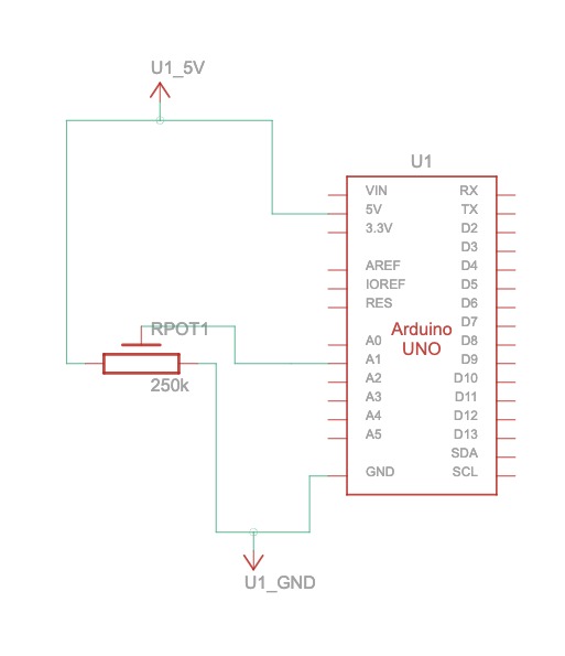
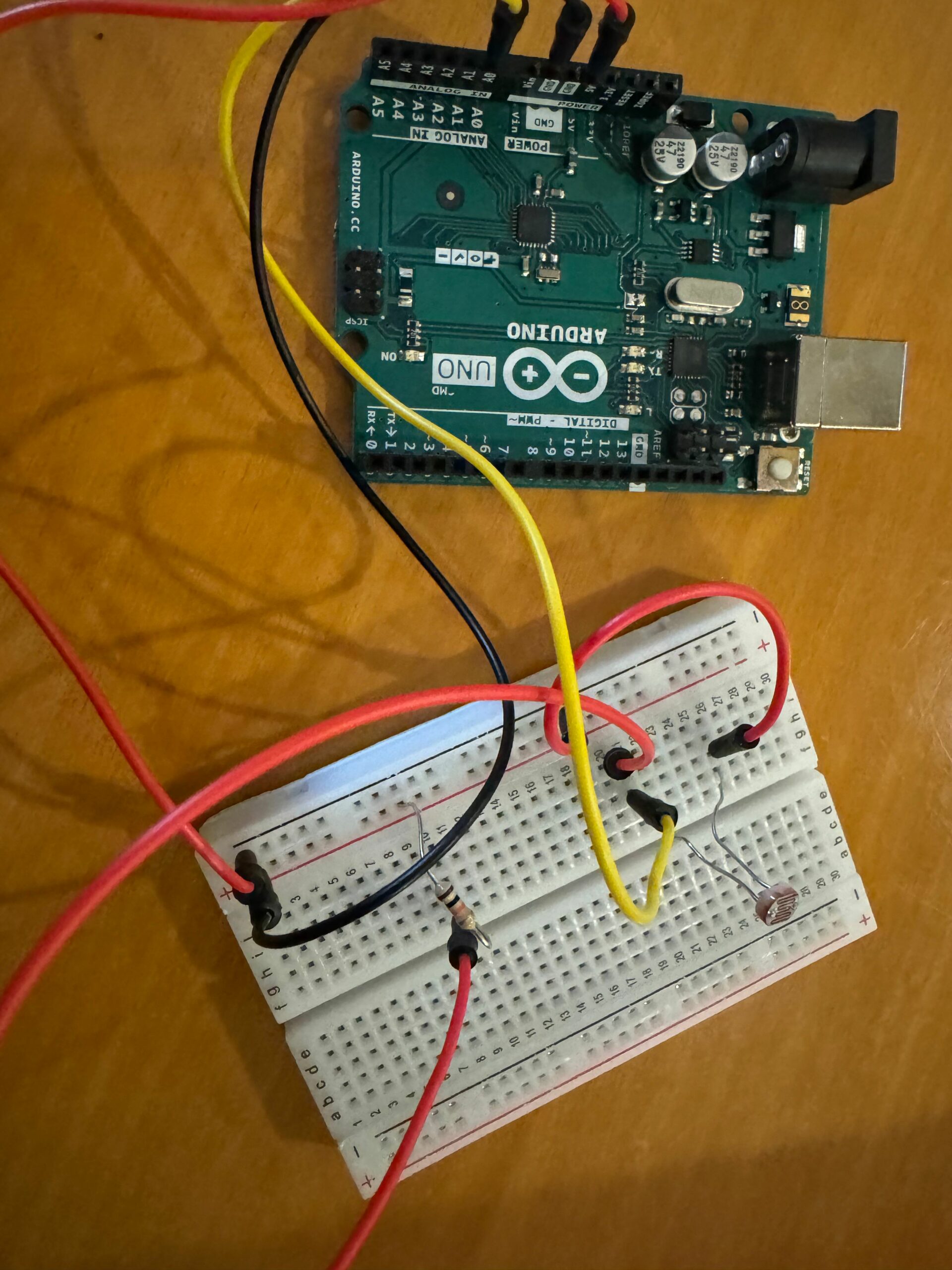
Exercise 1:
Circuit:
Code:
P5Js:
//Exercise 1 P5js Code

let ellipseX; // Variable to store ellipse's x-coordinate

function setup() {
  createCanvas(600, 400); // Create a canvas of 800x400 pixels
  ellipseX = width / 2; // Set initial x-coordinate of ellipse to middle of the screen
  noStroke(); // No stroke for the ellipse
}

function draw() {

  background(220); // Refresh background on each frame
  fill(0, 0, 255); // Set fill color to red
  ellipse(ellipseX, height / 2, 50, 50); // Draw ellipse at current x-coordinate and middle of the screen

  if (!serialActive) {
    text("Press Space Bar to select Serial Port", 20, 30);
  } else {
    text("Connected", 20, 30);}
}


function keyPressed() {
  if (key == " ") {
    // important to have in order to start the serial connection!!
    setUpSerial();
  }
}

// this callback function
function readSerial(data) {
  ////////////////////////////////////
  //READ FROM ARDUINO HERE
  ////////////////////////////////////

  if (data != null) {
    // make sure there is actually a message
    // split the message

    let fromArduino = split(trim(data), ",");
    // if the right length, then proceed
    if (fromArduino.length == 1) {
      // only store values here
      // do everything with those values in the main draw loop
//values from light sensor roughly ranged between 0 and 500,000 so map them between 0 and width of the screen
//use the mapped value as x-coordinate of the ellipse
      ellipseX = map(data,0,500000, 0,width);
    }

    //////////////////////////////////
    //SEND TO ARDUINO HERE (handshake)
    //////////////////////////////////
   let sendToArduino = fromArduino + "\n";
   writeSerial(sendToArduino);
  }
}
Arduino codes:
//Exercise 1 Arduino Code

void setup() {
  Serial.begin(9600); // Start serial communication at 9600 bps

  pinMode(LED_BUILTIN, OUTPUT);
// start the handshake
  while (Serial.available() <= 0) {
    //digitalWrite(LED_BUILTIN, HIGH); // on/blink while waiting for serial data
    Serial.println("0,0"); // send a starting message
    delay(300);            // wait 1/3 second
    //digitalWrite(LED_BUILTIN, LOW);
    delay(50);
  }
}
void loop() {

  // wait for data from p5 before doing something
    while (Serial.available()) {
    digitalWrite(LED_BUILTIN, HIGH); // led on while receiving data

  // Read sensor value
  int sensorValue = analogRead(A0);
   Serial.print(sensorValue);
  // Map sensor value to screen width
  int screenValue = map(sensorValue, 0, 1023, 0, 600);

  // Send mapped value to p5.js
  Serial.println(screenValue);

  delay(50); //    for stability
}
digitalWrite(LED_BUILTIN, LOW);
}
In future implementations, we may want the ball to move in a smoother fashion. We can consider adding codes that can smooth out the path of the ball’s movement. But using the photosensor to control the ball, we reinforce the knowledge about coding in Arduino and sending data from Arduino to p5.
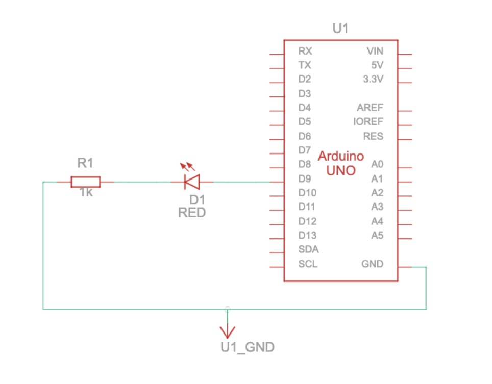
Exercise 2:
Circuit: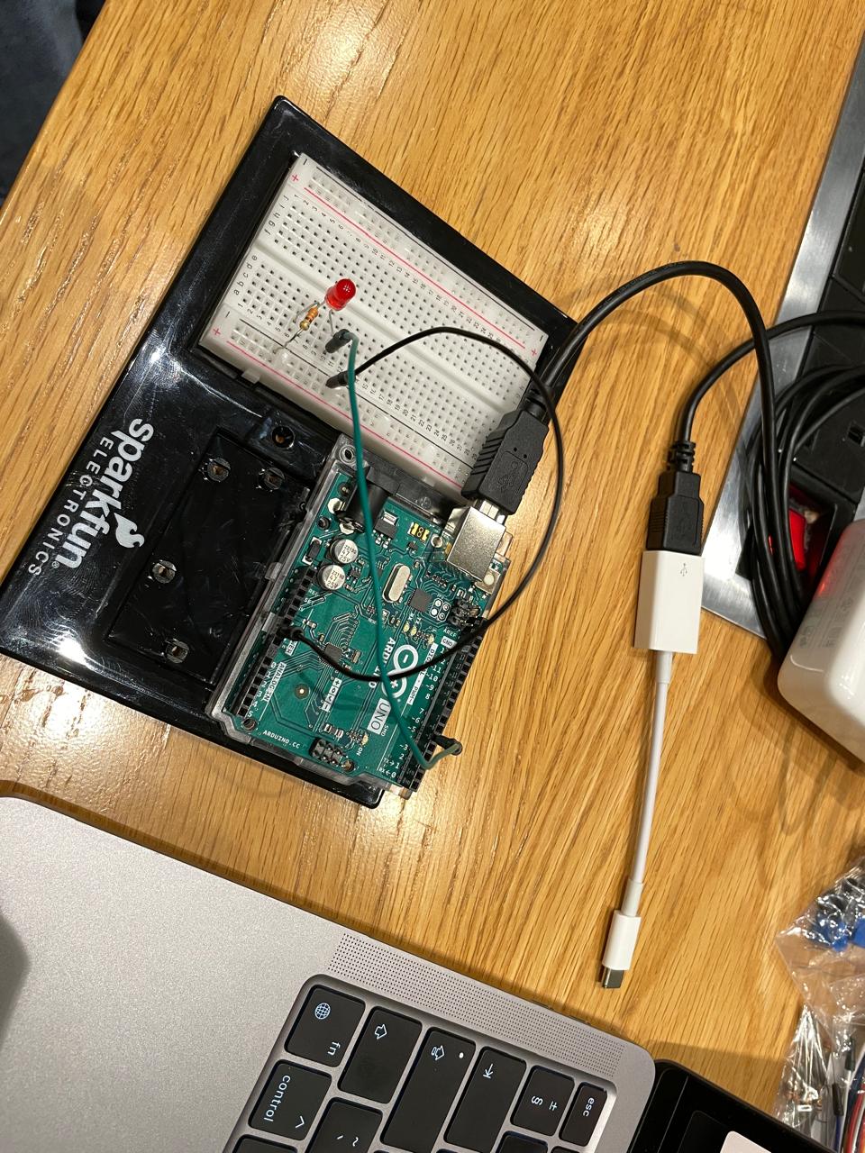
P5js code:
let rVal = 0;
let alpha = 255;
let left = 0; // True (1) if mouse is being clicked on left side of screen
let right = 0; // True (1) if mouse is being clicked on right side of screen
let slider;

function setup() {
  createCanvas(640, 480);
  textSize(18);
  slider = createSlider(0,255,0);
  slider.position(50,50);
}

function draw() {
  // one value from Arduino controls the background's red color
  background('white');

  // if (!serialActive) {
    text("Press Space Bar to select Serial Port", 20, 30);
  // } else {
  //   text("Connected", 20, 30);
  //   // Print the current values
    // text('rVal = ' + str(rVal), 20, 50);
  //   text('alpha = ' + str(alpha), 20, 70);
  // }


  // click on one side of the screen, one LED will light up
  // click on the other side, the other LED will light up
  // if (mouseIsPressed) {
  //   if (mouseX <= width / 2) {
  //     left = 1;
  //   } else {
  //     right = 1;
  //   }
  // } else {
  //   left = right = 0;
  // }
}

function keyPressed() {
  if (key == " ") {
    // important to have in order to start the serial connection!!
    setUpSerial();
  }
}

// This function will be called by the web-serial library
// with each new *line* of data. The serial library reads
// the data until the newline and then gives it to us through
// this callback function
function readSerial(data) {
  ////////////////////////////////////
  //READ FROM ARDUINO HERE
  ////////////////////////////////////

  if (data != null) {
    //////////////////////////////////
    //SEND TO ARDUINO HERE (handshake)
    //////////////////////////////////
    let sendToArduino = slider.value() + "\n";
    console.log(slider.value());
    writeSerial(sendToArduino);

    }

}
Arduino code:
int rightLedPin = 5;
int brightness = 0;

void setup() {
  // Start serial communication so we can send data
  // over the USB connection to our p5js sketch
  Serial.begin(9600);

  // We'll use the builtin LED as a status output.
  // We can't use the serial monitor since the serial connection is
  // used to communicate to p5js and only one application on the computer
  // can use a serial port at once.
  pinMode(LED_BUILTIN, OUTPUT);

  // Outputs on these pins
  // pinMode(leftLedPin, OUTPUT);
  pinMode(rightLedPin, OUTPUT);

  // Blink them so we can check the wiring
  // digitalWrite(leftLedPin, HIGH);
  digitalWrite(rightLedPin, HIGH);
  delay(200);
  // digitalWrite(leftLedPin, LOW);
  digitalWrite(rightLedPin, LOW);


  // start the handshake
  while (Serial.available() <= 0) {
    digitalWrite(LED_BUILTIN, HIGH); // on/blink while waiting for serial data
    Serial.println("0,0"); // send a starting message
    delay(300);            // wait 1/3 second
    digitalWrite(LED_BUILTIN, LOW);
    delay(50);
  }
}

void loop() {
  // wait for data from p5 before doing something
  while (Serial.available()) {
    digitalWrite(LED_BUILTIN, HIGH); // led on while receiving data

    // int left = Serial.parseInt();
    int right = Serial.parseInt();
    if (Serial.read() == '\n') {
      // digitalWrite(leftLedPin, left);
      analogWrite(rightLedPin, right);


      // int sensor = analogRead(A0);
      // delay(5);
      // int sensor2 = analogRead(A1);
      // delay(5);
      // Serial.print(sensor);
      // Serial.print(',');
      Serial.println();
    }
  }
  digitalWrite(LED_BUILTIN, LOW);

}
In terms of the future improvement for this one, we may want to control multiple LEDs with only one slider, or add more sliders to control many LEDs. But it helped us think about writing the code on transferring data to Arduino.
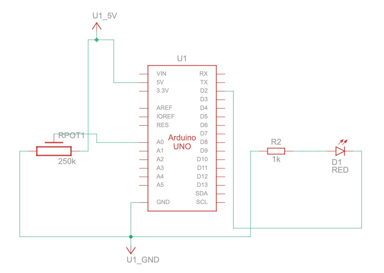
Exercise 3:
Circuit: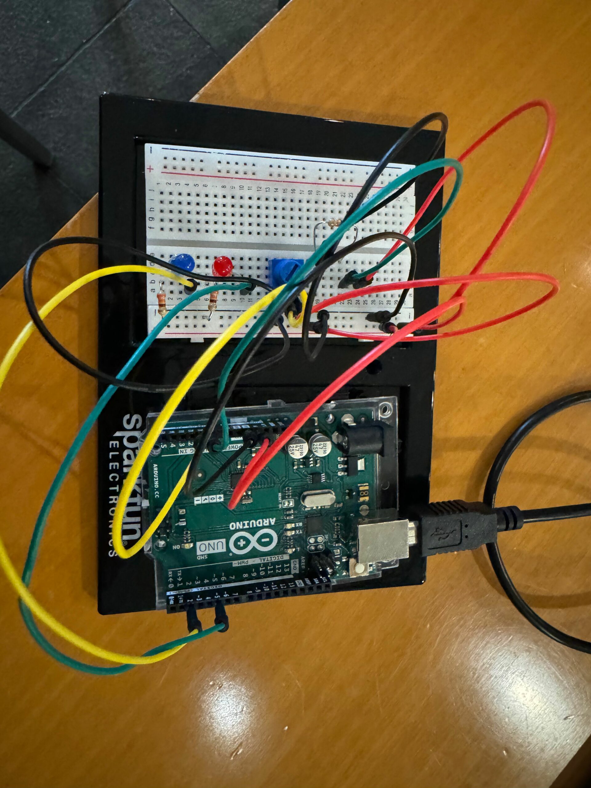 Code:
Code:
p5js code:
let velocity;
let gravity;
let position;
let acceleration;
let wind;
let drag = 0.99;
let mass = 50;
let rVal ;

function setup() {
  createCanvas(640, 360);
  noFill();
  position = createVector(width/2, 0);
  velocity = createVector(0,0);
  acceleration = createVector(0,0);
  gravity = createVector(0, 0.5*mass);
  wind = createVector(0,0);
}

function draw() {
  background(255);
  applyForce(wind);
  applyForce(gravity);
  velocity.add(acceleration);
  velocity.mult(drag);
  position.add(velocity);
  acceleration.mult(0);
  fill("blue");
  ellipse(position.x,position.y,mass,mass);
  if (position.y > height-mass/2) {
      velocity.y *= -0.9;  // A little dampening when hitting the bottom
      position.y = height-mass/2;
    }
  if (position.y == height - mass/2) {
      right = 1;
  } else {
      right = 0;
  }
  if (rVal > 522) {
    wind.x = 1;
} else if (rVal < 502) {
    wind.x = -1;
} else {
    wind.x = 0;
}


  // if (!serialActive) {
  //   text("Press Space Bar to select Serial Port", 20, 30);
  // } else {
  //   text("Connected", 20, 30);
  //   // Print the current values
  //   text('rVal = ' + str(rVal), 20, 50);
  //   text('alpha = ' + str(alpha), 20, 70);
  // }
}

function applyForce(force){
  // Newton's 2nd law: F = M * A
  // or A = F / M
  let f = p5.Vector.div(force, mass);
  acceleration.add(f);
}

// if (position.y == height - mass/2) {

//     //   left = 1;
//     // } else {
//       right = 1;
//     // }
//   } else {
//     // left = right = 0;
//   right = 0;
//   }

function keyPressed(){
  if (key == " ") {
    // important to have in order to start the serial connection!!
    setUpSerial();
  }
  // if (keyCode==LEFT_ARROW){
  //   wind.x=-1;
  // }
  // if (keyCode==RIGHT_ARROW){
  //   wind.x=1;
  // }
  if (keyCode==ENTER){
    // mass=random(15,80);
    position.y=-mass;
    velocity.mult(0);
  }
}

function readSerial(data) {
  ////////////////////////////////////
  //READ FROM ARDUINO HERE
  ////////////////////////////////////

  if (data != null) {
    // make sure there is actually a message
    // split the me ssage
    rVal=data;
    print(rVal);

    //////////////////////////////////
    //SEND TO ARDUINO HERE (handshake)
    //////////////////////////////////
    let sendToArduino = right + "\n";
    writeSerial(sendToArduino);
  }
}
Arduino code:
// Week 11.2 Example of bidirectional serial communication

// Inputs:
// - A0 - sensor connected as voltage divider (e.g. potentiometer or light sensor)
// - A1 - sensor connected as voltage divider
//
// Outputs:
// - 2 - LED
// - 5 - LED

// int leftLedPin = 2;
int rightLedPin = 5;

void setup() {
  // Start serial communication so we can send data
  // over the USB connection to our p5js sketch
  Serial.begin(9600);

  // We'll use the builtin LED as a status output.
  // We can't use the serial monitor since the serial connection is
  // used to communicate to p5js and only one application on the computer
  // can use a serial port at once.
  pinMode(LED_BUILTIN, OUTPUT);

  // Outputs on these pins
  // pinMode(leftLedPin, OUTPUT);
  pinMode(rightLedPin, OUTPUT);

  // Blink them so we can check the wiring
  // digitalWrite(leftLedPin, HIGH);
  digitalWrite(rightLedPin, HIGH);
  delay(200);
  // digitalWrite(leftLedPin, LOW);
  digitalWrite(rightLedPin, LOW);


  // start the handshake
  while (Serial.available() <= 0) {
    digitalWrite(LED_BUILTIN, HIGH); // on/blink while waiting for serial data
    Serial.println("0,0"); // send a starting message
    delay(300);            // wait 1/3 second
    digitalWrite(LED_BUILTIN, LOW);
    delay(50);
  }
}

void loop() {
  // wait for data from p5 before doing something
  while (Serial.available()) {
    digitalWrite(LED_BUILTIN, HIGH); // led on while receiving data

    // int left = Serial.parseInt();
    int right = Serial.parseInt();
    if (Serial.read() == '\n') {
      // digitalWrite(leftLedPin, left);
      digitalWrite(rightLedPin, right);
      // int sensor = analogRead(A0);
      // delay(5);
      int sensor2 = analogRead(A1);
      delay(5);
      // Serial.print(sensor);
      // Serial.print(',');
      Serial.println(sensor2);
    }
  }
  digitalWrite(LED_BUILTIN, LOW);
}
Challenges and implementations: we had no problem making the LED blink every time the ball touches the ground. But we did face some challenges in controlling the wind with the potentiometer initially. The ball kept moving to the left and we couldn’t figure out how to control it no matter what. In the end, we figure out that the issue lies in mapping and in coding the snippets of codes we want to send from p5 into Arduino. For improvements, we want to increase the speed of the ball being controlled by the potentiometer. At the moment, it is moving rather slowly.