Reading Reflection: Week 10

I liked how Tigoe described interactive art as conversation. Before I took this class, I wasn’t familiar with artworks that require the audience to interact with. Therefore, when it comes to art, I thought of paintings that simply express a thought/idea; in other words, artworks that state what the artist thinks. However, now that I have taken this class, I learned that art isn’t just about expressing the artist’s thoughts. It could be a conversation that the audience shares with the art itself. For that reason, for some artworks, the audience may not understand what the artwork is trying to deliver at first glance. Through interaction and conversation, the audience will gain an understanding of the artwork’s meaning.

Tigoe spoke to artists and asked them to shut up once they had set the initial statement so that the audience could interact through their senses. A good thing about interactive art, I believe, is that it is open to interpretation and gives the audience the freedom to expand on the meaning of the artwork. In this way, the artwork could reach a wider range of audience and be more entertaining.

An example of interactive art that caught my attention was “Tilty Stands and Tables”. This artwork required the audience to physically tilt the flat surfaces and experience the artwork’s response to the changes. Other than this, many other interactive artworks appealed to our senses. By calling the audience to physically interact with the artwork, the audience can freely interpret the meaning behind the work and add to their experiences. Now, with an understanding of what interactive art is, I am looking forward to sharing conversations with artworks and coming up with my interpretations.

Week 9 – LED and the Light Sensor

Concept and Idea:

I was working on an Arduino project in my core class, where we were playing with the light sensor and I thought about this idea to use for my unusual switch. So basically an LED using a light sensor: it reads the light level, converts it to a simplified scale, and then turns the LED on in dark conditions and off in light conditions. The sensor measures how much light is in the environment. Based on this measurement, the Arduino decides whether it’s dark or light around. If it’s dark, the LED turns on to provide light. If there’s enough light, the LED stays off. This setup is a practical way to automatically turn a light on or off depending on the surrounding light level.

Video:

Code:

const int sensorPin = A0;
const int ledPin = 7; 

// Initialize the setup
void setup() {
  pinMode(ledPin, OUTPUT); // Setup LED pin as an output
}

// Function to read and process light level
int readAndProcessLight(int pin) {
  int sensorValue = analogRead(pin); // Read the light sensor
  // Convert the sensor reading from its original range to 0-10
  return map(sensorValue, 1023, 0, 10, 0);
}

// Function to update LED status based on light level
void updateLedStatus(int lightLevel, int threshold, int pin) {
  if (lightLevel < threshold) {
    digitalWrite(pin, HIGH); // Turn LED on
  } else {
    digitalWrite(pin, LOW); // Turn LED off
  }
}


void loop() {
  int lightLevel = readAndProcessLight(sensorPin); // Read and process light level
  updateLedStatus(lightLevel, 6, ledPin); // Update LED status based on light level

  delay(200); // Short delay to avoid flickering
}


Improvements:

I was trying to incorporate the idea of replacing one LED light with 3 LED lights. With an RGB LED to enable color changes based on light levels. For example, so different colors could indicate different intensities of the light, and I was testing with the sunlight that was falling from my window, from morning to evening.

W10 Reading Reflection

As a creative, I often see art as a form of self expression, a statement made by an artist to convey a message to an audience. Providing detailed interpretations of specific works, you could describe what each element, color, composition of the work means and how the audience should interpret it. That was the way I was taught to go about my practice, which I was also going to bring in when creating interactive projects for this class. However after reading Tigoe’s post about physical computing, I saw my perspective shift. Tigoe makes the point that interactive art is actually not about making a statement but about how the project is able to serve as an instrument or environment that invites the audience to engage , interact, and interpret it. This forced me to see art as a point of communication and not simply a form of expression. It opened my eyes to the reality that my role as a designer, creative or artist is to simply set the stage, provide the context, and then take a step back. It is only when this is done will the true beauty of art, but more specifically, interactive art, lie. Therefore, when creating one should try to prioritize setting the stage for dialogue, creating an environment that invites the audience to interpret and interact with the art as they wish. 

Reading Tigoe’s second blog post about physical computing’s greatest hits and misses allowed me to see my new found understanding in action. Tigoe showcased different projects from faculty and students alike that showcase the essence of interactive art that he preached about in the first blog I mentioned. What I found really interesting is that all of these projects, although they have instructions, give freedom for the user to engage with the project in the way they seem fit. For example, the Gloves project allows for users to make a rhythm by moving your hands or fingers in a particular way. Even if everyone engages with it, the rhythms they create and the way they decide to go about using the project varies greatly based on individual movements, interpretations, and interaction. To me, this reaffirms the idea that interactive art is never the same for everyone and that it thrives on two things: collaboration and personal interpretation. If these foundational principles are not at the forefront during ideation and creation stages of interactive projects, we are left questioning: is it truly interactive, or is it merely a static piece of art masquerading as interactive?


My First Arduino Project – An Automatic Night Light ⚡️

For my first Arduino project, I decided to build a simple automatic night light that turns on when it gets dark. The basic concept is to use a photocell (light sensor) to detect light levels and then turn an LED on or off accordingly.

The Components:

– Arduino Uno board
– Photocell (light dependent resistor)
– LED
– Resistors
– Breadboard and jumper wires

The Concept:

A photocell is a resistor that changes resistance based on the amount of light hitting its sensor area. In bright light, the resistance is low allowing more current to flow. In darkness, the resistance is high restricting current flow.

I used this property to build a basic light sensor circuit. By connecting the photocell to one of the Arduino’s analog input pins, we can read its varying resistance values based on light levels. With some code to set a light threshold, we can then control an LED by turning it on when dark and off when bright.

const int led = 8;
const int sensor_pin = A0;
int sensor;
const int threshold = 500;

void setup(){
pinMode(led, OUTPUT);
Serial.begin(9600);
}

void loop(){
sensor = analogRead(sensor_pin);
Serial.println(sensor);
if(sensor<threshold){
digitalWrite(led,HIGH);
} else{
digitalWrite(led,LOW);
}
}

The end result is a compact night light that automatically lights up whenever the ambient light drops below the threshold level!

Future Development:
While functional, this is a very basic project. Some improvements I’d like to make are:

  • Make it portable by integrating a battery pack for a wireless night light
  • Design it into functional household objects like lamps, book lights, stair lights, etc.
  • Program different LED brightness levels based on duration of darkness

This first project taught me the basics of working with Arduino, simple circuits, analog inputs, and lighting control. I’m excited to level up my skills on more advanced projects!

Watch it in action here! :

IMG_4512

Unusual Switch

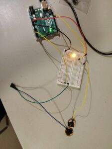
For the project, I was walking around my room and looking for creative ways to create a switch. Finally, I found two American pennies which are made from zinc and are coated with copper, both of which are good conductive materials. Then, I realized I could make a switch that works when the coins touch. Wires are taped to the coins so that when the coins touch, the circuit closes and lights up the yellow LED. I connected the green and blue wires together to extend the reach of the coins. The idea is similar to Carrom – the coin that has an extended reach has to be flung into the other coin which will be relatively stationary. The setup can be seen below.

Next, I write some code for the Arduino, so that when they touch, the LED stays lit for 3 seconds so that the contact is captured and a hit or miss can be seen clearly.

void setup() {
  // put your setup code here, to run once:
  pinMode(9, OUTPUT);
  pinMode(A5, INPUT);
}

void loop() {
  // put your main code here, to run repeatedly:
  int switchState = digitalRead(A5);

  if (switchState == HIGH){
    digitalWrite(9, HIGH);
    delay(3000);
  }
  else{
    digitalWrite(9, LOW);
  }
}

Week 9 Unusual Switch


For this week’s assignment, we were asked to make an unusual switch without any coding. The inspiration for this came from another project of mine. Back home, I  placed a switch and a simple circuit with an LED panel in my cupboard. A push-button switch is placed in between the hinges of the cupboard. Every time I open the cupboard door, the button gets pushed, and the LED panel lights up, making my life easier.

So, for this, I wanted to think of a simple switch that would make my life easier. I came up with the idea to make a switch that will light up a LED every time I step on it. Imagine waking up at night and taking a step; the LED would promptly light up, guiding your way.

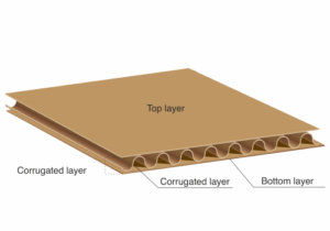
The concept for the switch was to use cardboard from delivery package and copper tape as a switch. Cardboard  will  be  placed  on  the  floor.  And  if there is  pressure  on  the  cardboard  the  LED  will  light  up. 

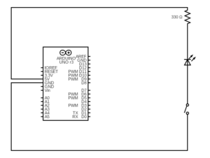
I placed one piece of copper tape on top of the bottom layer and another piece of copper tape under the top layer. So, if there is enough pressure, the in between corrugated layer gets squeezed, and both pieces of copper tape touch each other.  If the pressure gets released, the corrugated layer gets back to its original shape, and the switch disconnects. The copper tapes are connected in between the negative terminal of the LED and the ground of the Arduino. And the positive terminal of the LED is connected to the Arduino’s 5V pin through a 330 ohm resistor.

My Schematic Diagram

The main challenge I faced was deciding on the switch  material itself. I was sure that I wanted to replicate a floor that lights up if you step on it, and as soon as you step away, the LED should turn off, but I could not initially find a material that I could use a switch to replicate this behavior. The other challenging part was cutting the middle layer of the cardboard and placing the copper tapes carefully to avoid unwanted connections. In future, I would want to use any other sensor to detect if someone is stepping on the floor or not and turn on the LED accordingly.

Control LED by light – Week 9

Control LED by light

I created a straightforward project demonstrating a simple light-activated switch using a photoresistor. A photoresistor, also known as a light-dependent resistor (LDR), changes its resistance based on the amount of light it receives. When it’s dark, the resistance is high; when it’s light, it is low.

Components:

  • Arduino Uno
  • Photoresistor
  • Resistor (10 kΩ)
  • LED
  • Resistor (330 Ω)
  • Jumper wires

Setup:

  • Connect one leg of the photoresistor to the 5V pin of the Arduino and the other leg to a digital pin (e.g., pin 2) through a 10 kΩ resistor.
  • Connect the LED to another digital pin (e.g., pin 3) through a 330 Ω resistor.

Upload the following code to your Arduino:

int photo = A0;
int led = 7;

void setup() {
  pinMode(led, OUTPUT);
}

void loop() {
  int lightRaw = analogRead(photo);
  int light = map(lightRaw, 1023, 0, 10, 0);

  if (light < 6) {
    digitalWrite(led, HIGH);
  }

  else {
    digitalWrite(led, LOW);
  }
}

Future Developments

  • One potential future development for this project would be to create a more sophisticated light-activated switch that could be used in various applications. For example, the switch could turn on lights automatically when it gets dark or open and close doors or windows.
  • Another possibility would be integrating the switch into a more extensive system, such as a home automation system. This would allow users to control their lights and other devices with their smartphones or tablets.
  • Additionally, the switch could be made more user-friendly by adding features such as a dimmer switch or a timer. This would allow users to customize the switch’s behavior to suit their needs.
    Overall, this project has many potential future developments. With creativity and ingenuity, the light-activated switch could be used in various ways to make our lives easier and more convenient.I had a lot of fun with this assignment! It was really cool to see how a simple idea could be turned into a daily application that we can use to save electricity.

Week 9 – Unusual Switch

Concept

For this assignment, the task is to create an creative switch that doesn’t require manual activation or coding. Drawing from a personal challenge of frequently and leaving the essential cards like the room and NYUAD access cards in my dorm room, the aim is to design a solution that addresses this issue. The proposed idea is to create a switch that lights up when the wallet is kept in the room and dims when it’s taken out.

Process

So for this project the materials and components used were red LED light, 330 ohm Resistor, 4 Wires, Aluminum foil, tape, Breadboard, and Arduino board. The breadboard circuit connection is shown below:

Video Demonstration

Future Improvements

Sound Effects: I would like to add music or sound effects for a more engaging experience. For example, a pleasant tune could play when the wallet is detected, enhancing user interaction.

Aesthetic Enhancements: I would like to add visual appeal with colorful LEDs or creative casing designs. This will make the device more attractive and blend better with the room decor.

Blinking Lights: I would also like to modify the lights to blink continuously instead of remaining constantly on, which would need some coding integrations.


Week 9: Laptop Charging Switch

Concept: While browsing YouTube for ideas, I noticed that my friend’s old laptop lacks an indicator light for charging. Every time she plugs it in, she’s uncertain if it’s actually charging. So, for my Week 9 project, I’ve decided to help her by using an Arduino to create a simple input/output switch. This will make it easy for her to tell whether her laptop is charging.

Fig 1: This is laptop we will be using for making a switch.


Fig 2: A closer look of connection between laptop and charging cable.

So the ultimate goal of this project is to incorporate an LED that will serve as an indicator when the charging plug is connected to the laptop.

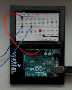
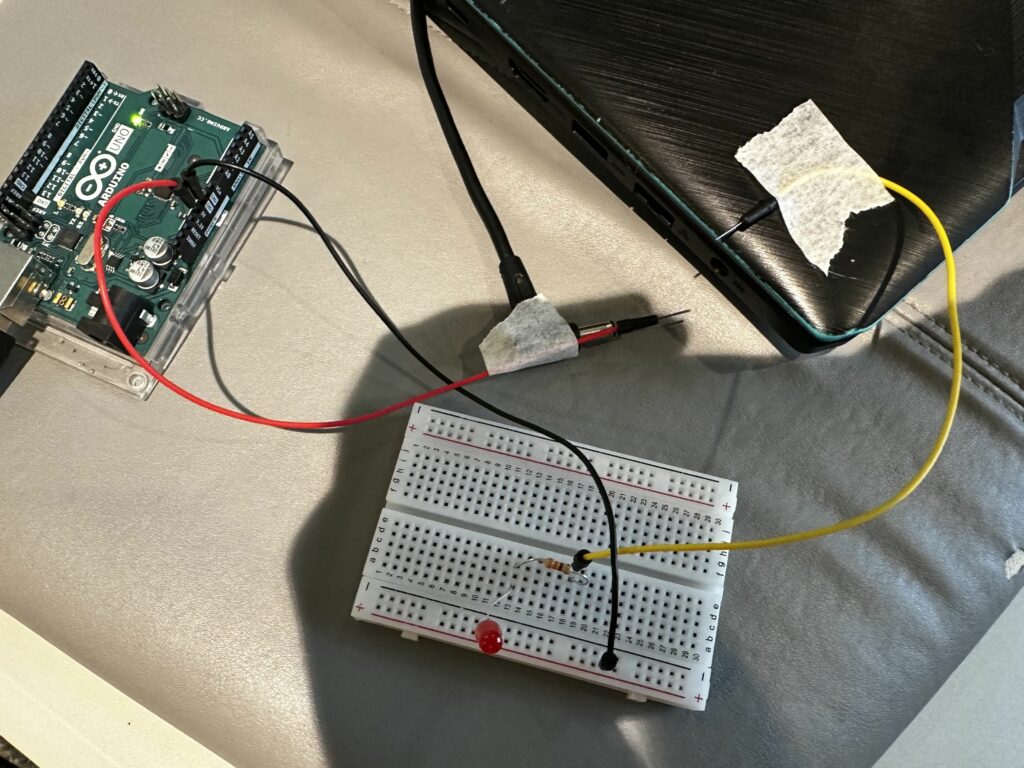
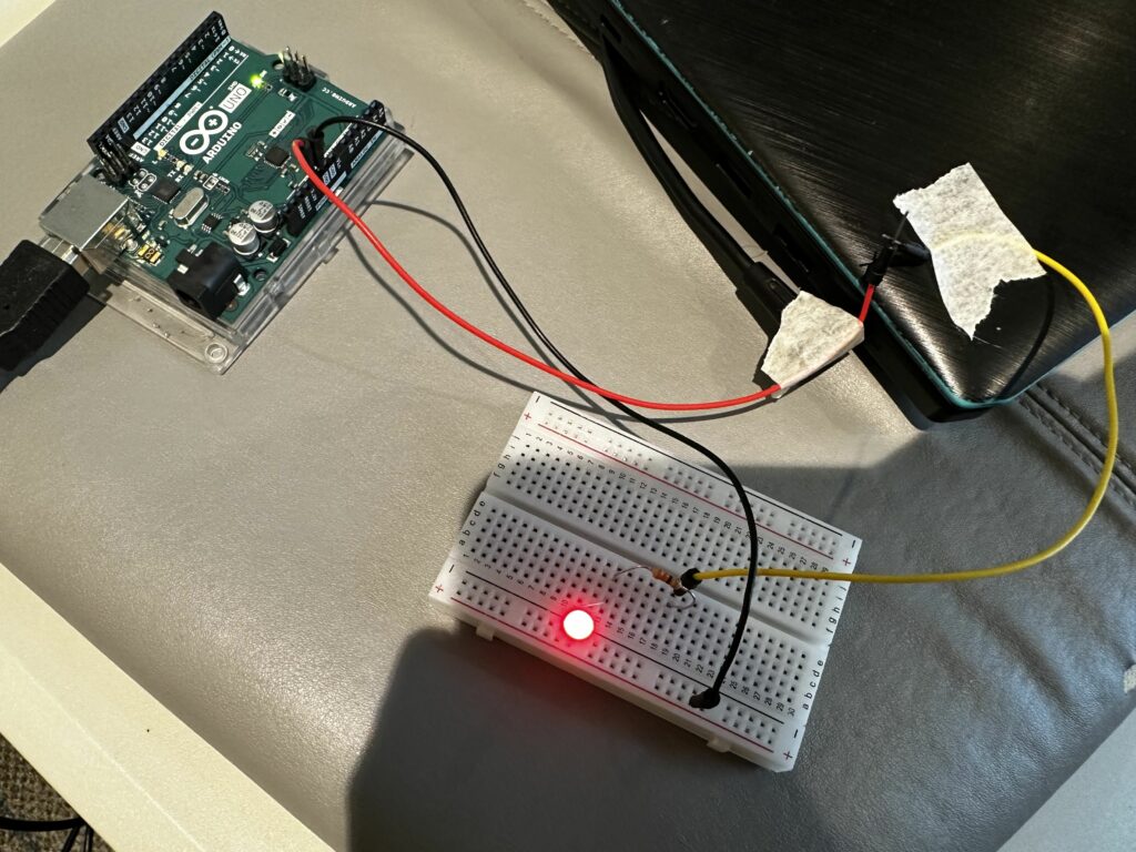
Process: First, I built a basic circuit that uses an Arduino to power a breadboard. I included a red led in the circuit to serve as an indicator of whether the circuit is complete.  So the red wire is supplying power (+5V from the Arduino) to the longer, positive leg of the LED. The shorter, negative leg of the LED is connected to one end of a resistor. The other end of the resistor is connected back to the Arduino board via the black wire, which completes the circuit to GND (ground), allowing the current to flow. When the circuit is closed, a red led turns on. If the circuit is interrupted or there is a break between two wires, then the red led turns off.

Fig 3: An Open or Broken Circuit, The Red Led is in “Off” state.

Fig 4: A Closed Circuit, The LED is in “ON” State.

Components I used:

1) Three jumper wires
2) A Red LED
3)  Arduino
4) A Resistor
5) A USB Cable for connecting Laptop with Arduino
6) A Breadboard
7) A Tape

Video Demonstration:

Link to this video.

Challenges and Future Improvements:

1) Working on this basic circuit board isn’t very challenging for me. However, I find it a bit tricky to attach the wires with tape in such a way that they make a complete connection when the charging cable is plugged in. Getting the angle right for this connection is the challenging part.

2) So for future improvements, I’m considering to use a sensor that can automatically detect whether the cable is connected or disconnected, and do so wirelessly. This would enhance the system’s functionality and user convenience.

Concept:

The concept behind my Unusual Switch project is to transform a regular room door into an innovative electrical switch. This unconventional approach leverages the movement of the door to control the on and off state of an LED light.

Demonstration:

Circuit:

Execution:

I set up a simple circuit with a resistor and an LED. Starting with a ground wire connected to the LED, which then connects to a resistor. To integrate the door into this circuit, I attached one wire wrapped in aluminum foil to the door frame and another, connected to 5V, similarly wrapped and placed on the door. A long strip of aluminum foil on the door’s moving part completes the circuit when the door is closed, lighting up the LED. Open the door, and the circuit breaks, turning off the LED. It’s a neat little setup that turns the action of opening and closing a door into an on-off switch for the light.