Potentiometer Switch

I came up with the idea of this assignment while playing around with the potentiometer. It has a wide range of values it can provide and I wanted to utilize the potential of its variability and precision.

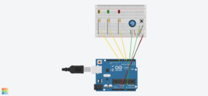
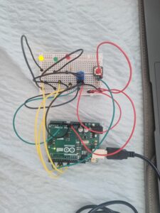
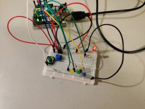
There are 4 LEDs – red, yellow, green and blue – that light up as the values generated by the variable resistor change. The potentiometer is the analog sensor here, but provides functionality of both an analog and a digital sensor. The purely digital sensor here is the green button.

The potentiometer values are supplied to the digital output pins and control the brightness of the LEDs. The value range of the potentiometer is also split into 4 equal segments, so that each LED only has a quarter of the full range of brightness it can take. The splitting also allows to switch the LED as the value changes, meaning for (0, 256] range of the potentiometer reading, one LED lights up with (0, 1/4] of its brightness range. Same logic applies to the other LEDs in a successive fashion.

The green button  (digital sensor) allows to change the sequence of LEDs that light up with certain values of the potentiometer. For instance, if initially the red LED has the lowest quarter of values, the switch sets that lowest range to the next LED in succession, which would be the yellow one, and every LED gets the position of the next one, hence in this example the red one would get the highest range of values and be the brightest if turned on. The video of how the system works is attached below.

The main code responsible for the button and the value switches is provided below. The relatively challenging part was figuring out a way to make the switch between what values which LED gets, and I ended up with an array structure for efficiency.

if (buttonState == HIGH){
    if (swapped == 0){
    switchState += 1;
    switchState = switchState % 4;
    }
    swapped = 1;
  }
  else{
    swapped = 0;
  }

  if (sensorValue > 0 && sensorValue <= 256){
    analogWrite(leds[switchState], sensorValue/4);
    digitalWrite(leds[(switchState+1)%4], LOW);
    digitalWrite(leds[(switchState+2)%4], LOW);
    digitalWrite(leds[(switchState+3)%4], LOW);
    //speed = 2000;
  }
  else if(sensorValue > 256 && sensorValue <= 512){
    digitalWrite(leds[switchState], LOW);
    analogWrite(leds[(switchState+1)%4], sensorValue/4);
    digitalWrite(leds[(switchState+2)%4], LOW);
    digitalWrite(leds[(switchState+3)%4], LOW);
    //speed = 1000;
  }
  else if(sensorValue > 512 && sensorValue <= 768){
    digitalWrite(leds[switchState], LOW);
    digitalWrite(leds[(switchState+1)%4], LOW);
    analogWrite(leds[(switchState+2)%4], sensorValue/4);
    digitalWrite(leds[(switchState+3)%4], LOW);
    //speed = 500;
  }
  else if(sensorValue > 768 && sensorValue <= 1023){
    digitalWrite(leds[switchState], LOW);
    digitalWrite(leds[(switchState+1)%4], LOW);
    digitalWrite(leds[(switchState+2)%4], LOW);
    analogWrite(leds[(switchState+3)%4], sensorValue/4);
    //speed = 250;
  }
  else{
    digitalWrite(red, LOW);
    digitalWrite(yellow, LOW);
    digitalWrite(green, LOW);
    digitalWrite(blue, LOW);
    //speed = 0;
  }

For improvements, I could add more variability into what the button does, possibly incorporate flickering rate for different potentiometer readings to make the transitions more clear. I also could optimize the code and make it more reusable so that when new functionality or LEDs are added, it does not take much code to incorporate.

Week 10: Reading Response

First Article: Physical Computing’s Greatest Hits (and misses)

After reading this article, I find myself reflecting on its crucial aspects. The author discusses various themes in physical computing and highlights recurring project ideas. One point raised is the versatility of these themes, allowing for originality despite their frequent use. I can see evidence of this in the examples provided, such as the theremin-like instruments and gloves used for musical interaction. However, I wonder if the author’s enthusiasm for these themes might overshadow potential limitations or drawbacks. While the projects are indeed versatile and popular, are there certain constraints or challenges that aren’t fully addressed? Additionally, the emphasis on creativity and variation might suggest a bias towards celebrating the potential of physical computing without thoroughly examining its limitations or pitfalls.

Reading this has not drastically changed my beliefs, but it has prompted me to consider the balance between creativity and practicality in project development. Are there instances where prioritizing creativity might hinder the functionality or effectiveness of a physical computing project Furthermore, the discussion of themes like “Remote Hugs” and “Meditation Helpers” raises questions about the effectiveness of technology in facilitating emotional experiences. Can machines truly simulate or enhance human connection and emotional well-being, or do they risk oversimplifying complex human experiences?

Overall, I think while the reading offers valuable insights into the world of physical computing, sententiously it also prompts critical thinking about the intersection of technology and human interaction.

Second Article: Making Interactive Art: Set the Stage, Then Shut Up and Listen

After reading this article, I find the author’s perspective on interactive art thought-provoking. They emphasize the importance of not interpreting one’s own work in the context of interactive art. Instead, the author suggests setting the stage for interaction and then allowing the audience to interpret and respond to the artwork in their own way. I agree with the notion that providing interpretation alongside interactive art can limit the viewer’s experience by dictating how they should perceive and engage with the piece. By allowing space for individual interpretation, the artwork becomes a platform for dialogue between the artist and the audience.

The comparison made between planning interactive artwork and directing actors resonates with me. Just as a director guides actors without imposing specific interpretations, an artist should create opportunities for interaction without prescribing meaning. This approach allows for more authentic and varied responses from the audience. However, I wonder about the balance between providing context for interaction and leaving room for interpretation. How can an artist effectively guide the audience’s engagement without imposing their own biases or intentions?

Furthermore, the idea of interactive artwork as a performance highlights the dynamic nature of the audience’s role in completing the work. How can artists create environments or stimuli that encourage meaningful interaction and exploration without overshadowing the audience’s agency?Overall, I feel the article challenges traditional notions of authorship and interpretation in art, encouraging a more open and collaborative approach to creating interactive experiences.

Week 10 | Proximity-activated LEDs

Concept

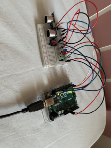
For this week’s assignment , we were required to take an analog and a digital input from two sensors to control two LEDs . I decided to use a slide switch for the digital input and the ultrasonic sensor for the analog input (distance of an object from the sensor). The slide switch is used to switch between the two LEDs that are of different colors . The ultrasonics sensor is used to detect the distance of an object from it. As an object gets closer and closer, the LED gets brighter and brighter. This could be  as some kind of an alert switch that grows bright when an object gets closed to it . It could be used for automatic proximity lighting or in security systems.

Schematics

I used tinkerCAD to simulate my project and generate the schematics below:

Schematic Diagram

View on TinkerCAD


List of Components


Code

I am using a library called newPing that handles input from the sensor HC-SR04 (ultrasonic distance sensor). The code is given below:

#include <NewPing.h> // Include the NewPing library

//Created by Aadil Chasmawala

const int LEDPin1 = 3; // Define LEDPin1 as a constant integer
const int LEDPin2 = 5; // Define LEDPin2 as a constant integer
const int switch_PIN= 10; //switch PIN
int brightness1;
int brightness2;
NewPing Mysensor(8, 7, 200); // Trigger pin = 8, echo pin = 7, max_distance = 200cm

void setup() {
  pinMode(LEDPin1, OUTPUT); // Set LEDPin1 pin mode to output
  pinMode(LEDPin2, OUTPUT); // Set LEDPin2 pin mode to output
  pinMode(switch_PIN,INPUT); 
  Serial.begin(9600); // Initialize serial communication
}

void loop() {
  int distance = Mysensor.ping_cm(); // Get the distance in centimeters
  Serial.println(distance); // Print the distance to the serial monitor
  if(distance > 50){ //if distance is more than 50 , switch the LED off
    brightness1=0;
    brightness2=0;
  }
  else{
  // Map the distance to the brightness of the LEDs
  brightness1 = map(distance, 0, 50, 255,0); // Adjust the range as needed
  brightness2 = map(distance, 0, 50, 255,0); // Adjust the range as needed
  }

  // Set the brightness of the LEDs
  bool state = digitalRead(switch_PIN);
  Serial.println(state);

  if(state == HIGH){ // if switch is in one state (towards 5V)
  analogWrite(LEDPin1, brightness1);
  analogWrite(LEDPin2,0);
  }
  else if (state == LOW){ //if the slide switch is towards ground
  analogWrite(LEDPin2, brightness2);
   analogWrite(LEDPin1,0);
  }

  delay(100); // Wait for a short time before taking another measurement
}


Video Demonstration/ Images

Link to the video- https://youtu.be/Unpllzq1EK8

Challenges and Reflections

I had some issues in using push buttons for the digital input as there would be a noticeable delay between when the button was released and the detection of that release. However, this was resolved by using a slide switch instead of a button switch.

Since I am using a library called <newPING.h>, I don’t have to worry about sending and receiving pulses from the trigger and echo pins respectively. The ping_cm handles it . At some point, the sensor was not working as expected so I printed the value of distance in the serial monitor for debugging and was able to resolve the issue.

Overall, I am happy with the way the brightness of LED changes with the distance and the quick switching of LED using a slide switch. For future projects, I hope to continue experimenting with different inputs and use them in creative ways.

Week 10: Reading Response

Physical Computing’s Greatest Hits (and misses)

This reading allowed me to think of physical computing in a different approach. When coming up with ideas for a project, I usually take so much time to think of something that has never been done before. After looking at these works, they are merely inspired by other artists’ works, in which they may have similar themes in terms of interaction but also convey completely different messages and ideas. The works shown inspired me to think of my own iteration of these themes and ideas.

Making Interactive Art: Set the Stage, Then Shut Up and Listen

While reading this, it reminded me of a previous reading we had, The Design of Everyday Things by Don Norman. Norman thinks that a design of something should communicate how it is going to be used. Similarly, this reading also tells us about how our artwork doesn’t have to give out instructions to others. We should allow our audience to interpret it themselves and receive feedback from them to adjust our work accordingly.

Week 10 – EID Decoration

Concept

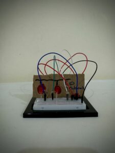
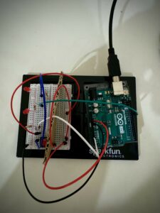
For this assignment, the task is to get information from at least one analog sensor and at least one digital sensor (switch), and use this information to control at least two LEDs, in both digital and analog way. Since its EID and after drawing some inspirations from previous works done by a student, I’ve decided to make an EID decoration using the LED lights.

Materials I used

  1. Arduino Uno board
  2. 2 LEDs (RED)
  3. 2 x 220-ohm resistors
  4. 10k-ohm resistor
  5. Tactile push-button switch
  6. Photocell
  7. Breadboard
  8. jumper wires
  9. A piece of cardboard

How it works

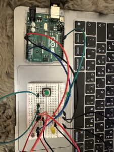
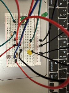
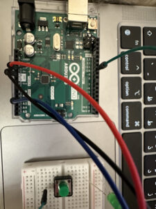
The goal is to turn on both LEDs to light up the Eid decoration. To do this, you press one button to light up one LED. Then, to turn on the other LED, you block the photocell’s light by placing your finger over it. When you do both actions together (pressing the button and blocking the photocell), both LEDs will light up at the same time.

Code

int led = 11;
int brightness = 0;

void setup() {
  // put your setup code here, to run once:
  Serial.begin(9600);
  pinMode(led, OUTPUT);

}

void loop() {
  // put your main code here, to run repeatedly:

  int sensorValue = analogRead(A2);
  Serial.println(sensorValue); //prints the sensorValues

  sensorValue = constrain(sensorValue, 410, 450);
  brightness = map(sensorValue, 410, 450, 255, 0); //mapping the sensorValues

  analogWrite( led, brightness);

  delay(30);

}

Video Demonstration

Future Improvements

In future updates, I want to include a condition where simply activating the button or just the photocell won’t turn on the LEDs. Instead, both the button and photocell need to be activated simultaneously to light up the LEDs.

Week 10 – “Interactive Color Toy”

Concept

After completing my project, I began contemplating a creative concept for it. It occurred to me that if I had a child, I would use this project as a toy to help them quickly learn colors. Consequently, I decided to name this project the “Interactive Color Toy.” Children can use it as a toy, pressing a button to cycle through three colors: red, yellow, and green. Additionally, they can adjust the LED’s brightness using a potentiometer. By pressing the button and changing the brightness, children could easily learn colors through tactile experiences, especially if parents help by naming the colors that appear when the button is pressed.

Circuit

My circuit consists of the following elements:

– Arduino board (e.g., Arduino Uno)

– Potentiometer

– Push button switch

– LED

– Resistors

– Breadboard

– Jumper wires

In this circuit, a potentiometer is connected to an analog input pin of the Arduino, allowing it to read varying voltage levels. A push button is connected to a digital input pin, enabling the Arduino to detect button presses. Three digital output pins are connected to the red, green, and yellow pins of the LED, respectively. By adjusting the potentiometer, users control the brightness of the LED colors, while pressing the button cycles through the available colors.

Code

// Pins
const int POTENTIOMETER_PIN = A0; // Analog input pin for potentiometer
const int BUTTON_PIN = 2; // Digital input pin for push button
const int RED = 5;  // Digital output pin for RGB LED (red)
const int GREEN = 6;  // Digital output pin for RGB LED (green)
const int YELLOW = 9; // Digital output pin for RGB LED (yellow)

// Variables
int potentiometerValue = 0; // Potentiometer value
bool buttonState = false; // Button state
int colorIndex = 0; // Index of current color

void setup() {
  pinMode(POTENTIOMETER_PIN, INPUT);
  pinMode(BUTTON_PIN, INPUT_PULLUP);
  pinMode(RED, OUTPUT);
  pinMode(GREEN, OUTPUT);
  pinMode(YELLOW, OUTPUT);
}

void loop() {
  potentiometerValue = analogRead(POTENTIOMETER_PIN);
  
  // Map potentiometer value to LED brightness
  int brightness = map(potentiometerValue, 0, 1023, 0, 255);
  
  // Set the LED color based on the current color index
  switch (colorIndex) {
    case 0:  // Red
      analogWrite(RED, brightness);
      analogWrite(GREEN, 0);
      analogWrite(YELLOW, 0);
      break;
    case 1:  // Green
      analogWrite(RED, 0);
      analogWrite(GREEN, brightness);
      analogWrite(YELLOW, 0);
      break;
    case 2:  // Yellow
      analogWrite(RED, 0);
      analogWrite(GREEN, 0);
      analogWrite(YELLOW, brightness);
      break;
  }

  // Check button state
  if (digitalRead(BUTTON_PIN) == LOW) {
    if (!buttonState) {
      // Toggle color index
      colorIndex = (colorIndex + 1) % 3;
      buttonState = true;
      delay(200);
    }
  } else {
    buttonState = false;
  }
}

This is my code. The analogRead function reads the value from the potentiometer, which is then mapped to control the brightness of the LED colors. The switch statement selects the appropriate color based on the current color index, and the digitalWrite function sets the brightness of the corresponding LED pins accordingly. When the button is pressed, the color index is incremented to cycle through the available colors.

Improvements and Overview

Overall, I enjoyed this assignment, particularly the aspect of controlling outputs using different physical inputs. The most challenging part was figuring out how the current moved through the circuit. However, I was able to easily determine the correct way to connect all the components. As a further improvement, I considered expanding the color palette by using a full RGB LED instead of individual colors. This would allow for a wider range of colors and more creative possibilities.

Luke Nguyen – Week 10 Reading

I was particularly fascinated by the Gloves section in the Physical Computing’s Greatest Hits reading. It is interesting to learn how engineers created the gloves that could respond to the movements of fingers to make rhythm; I wondered how they created and programmed the force-sensing resistors so that when attached to the fingertips, these sensors would know what kinds of triggers to create according to how strong the forces are. A few years ago, I was amazed at how Ariana Grande could control music with her gloves during her Honeymoon Tour in 2015. Here are a few videos of the way she did it: video 1, video 2. After doing some research, I discovered that she was using the Mi.Mu Gloves developed by MI.MU GLOVES LIMITED (UK) which enables music through movement as the company advertised. During her tour, Ariana used the motions and forces of her gloved hand gestures to add effects to her live performances, for example: holding up one finger to add harmony, opening her palm to add major-sounding harmonies, etc. I didn’t know back then that this technology is called physical computing; it was physical computing that enabled her to do this. In retrospect, it is amazing how physical computing has opened up countless opportunities for musicians to create and control their music both in studio and live environment. This glove technology is a mega hit to them.

I resonate with the author’s point in the second article “Making Interactive Art: Set the Stage, Then Shut Up and Listen”. I think artists’ intentions while making the interactive artworks are important but the audience’s experience is equally important as well. Most of the time when I see an interactive artwork, it is interactive in itself but not to the spectators, which I find to be rather frustrating. One time when I was visiting the Museum of Natural Science, there was a very awesome exhibition about nature that I remembered till this day. The exhibition was showcased in a sphere. When visitors stepped inside, they would directly interact with the elements of nature through their feet. One would step on the elements, for example, water, leaves, wind, bubbles, butterflies, etc. to see how they would become interactive. I got no instructions on how to interpret the artwork but I learned how to interact with it purely through interacting with it. I felt alive; I felt that was such a unique experience; the artwork made me want to play with it again and again. In contrast, most of the interactive artworks I had seen before this one were presumably “interactive” but I wasn’t given any opportunity to interact with them. I did not know how to feel viscerally towards what I was observing, which I think made the objects hardly memorable without photography after moving on from them.

Week 10: Digital and Analog

Concept:

The idea of this assignment is to have differently controlled LED lights. In this example, they act as lights outside of an airplane bathroom. When the bathroom is occupied, the yellow light is either on or off (digital) . When it is unoccupied, the green LED senses that there is no light in the room and therefore turns on the green light gradually (analog). This can also be used in a parking lot which depicts whether a parking is available or not.

Watch here:

IMG_4713

IMG_4713

For the analog pin, I used pin 10, with A2 used for the input. I used both resistors for it, the 10K and 330 ohm ones. As for the digital pin, it only required the 330 ohm resistor.


Code:

int led = 10;         // the PWM pin the LED is attached to
int brightness = 0;  // how bright the LED is

// the setup routine runs once when you press reset:
void setup() {
  Serial.begin(9600);
  // declare pin 10 to be an output:
  pinMode(led, OUTPUT);
}

// the loop routine runs over and over again forever:
void loop() {
  int sensorValue = analogRead(A2);

  sensorValue = constrain(sensorValue, 30, 210);

  analogWrite(led, sensorValue/4);

  brightness = map(sensorValue, 30, 210, 0, 255);

  Serial.println(sensorValue);

  // wait for 30 milliseconds to see the dimming effect
  delay(30);
}

Difficulties:

As I was working on it, I struggled so much with trying to get both LED lights to work at the same time as they both needed power from 5V. A few  LED lights were burnt while figuring that out. Eventually, I knew how to fix that by connecting two wires to the 5V wires then connecting those to each input (button and photoresistor).

Luke Nguyen – Week 10 Assignment – Thanos Snap


Concept & Inspiration:

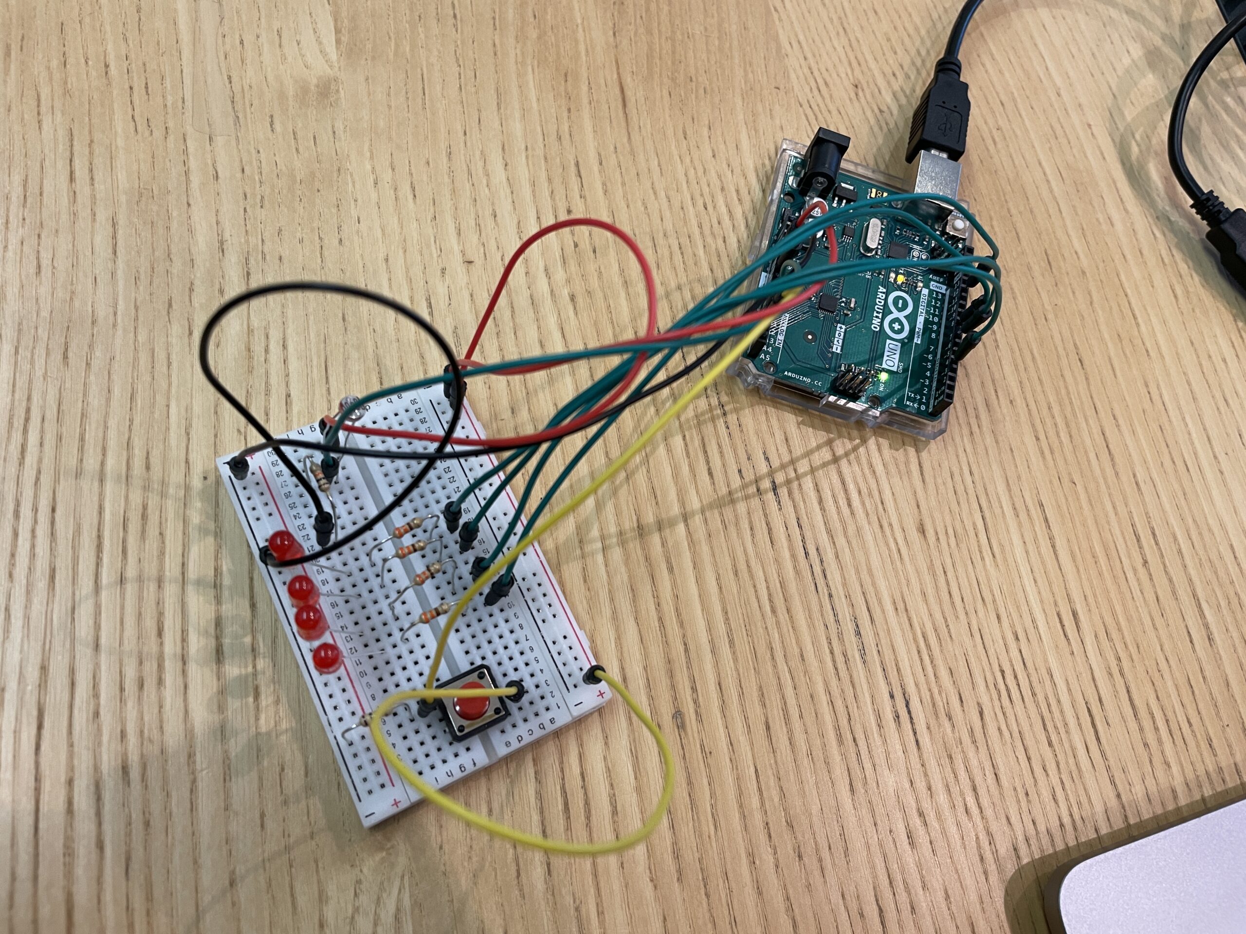
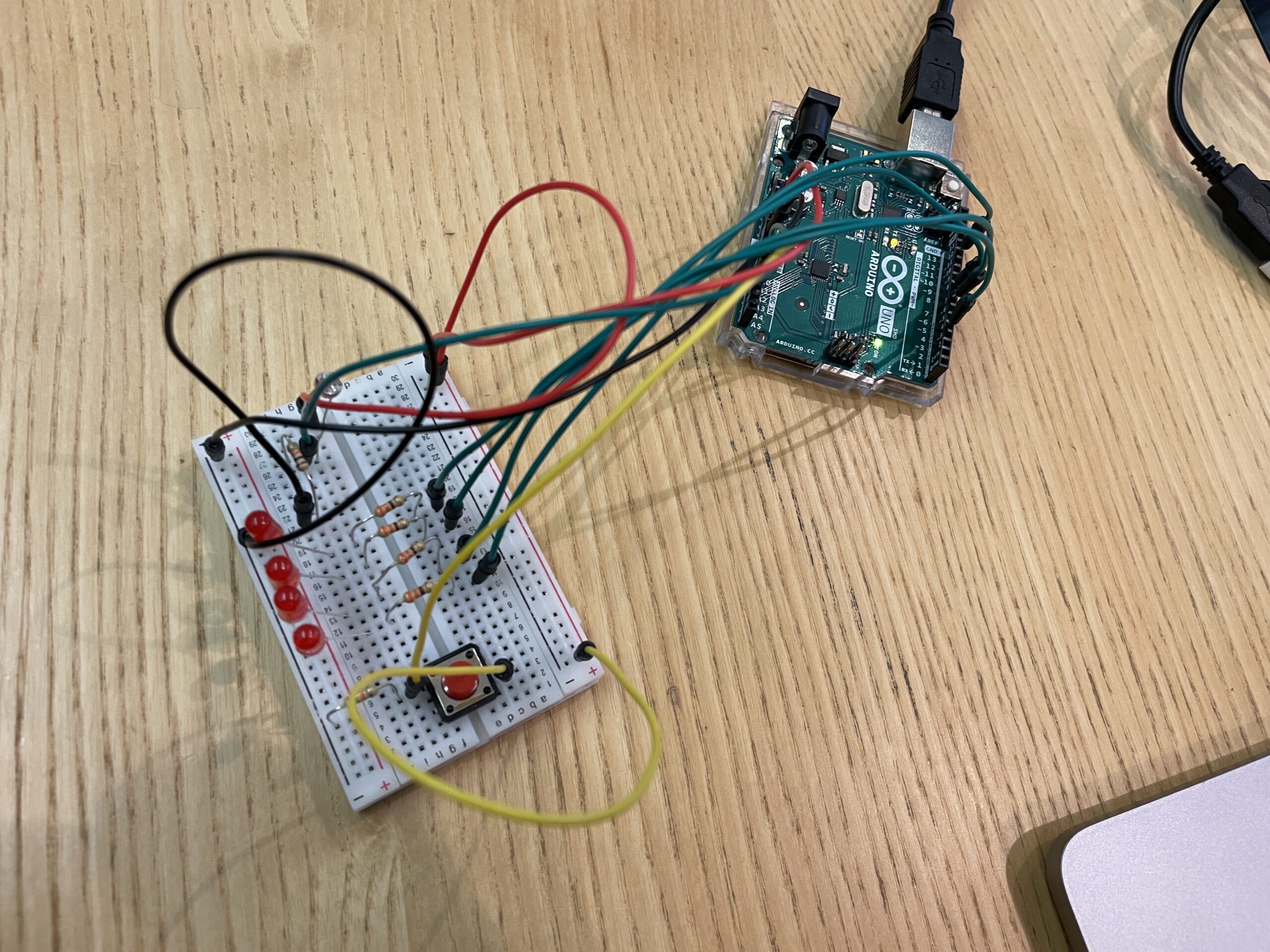
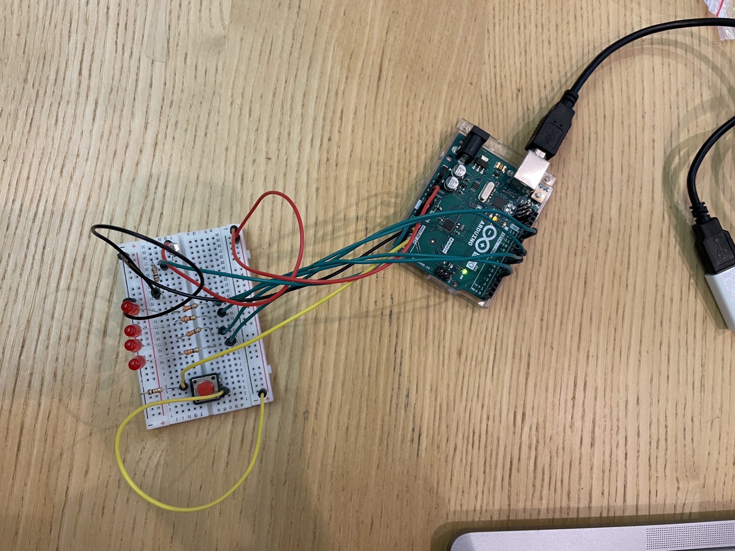
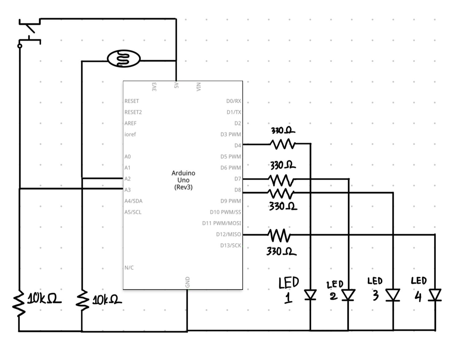
I thought of Thanos in Marvel Comics while I listened to a song by Beyoncé where he is referenced. Analog versus sensor seems to be a duality that reminds me of the notion of half and half that Thanos is fervent believer of. He believes that if he wipes out half of the population of the universe, he could restore its balance (half-populated and half-empty); fully populated would tip the scale. This assignment is set in that universe. I want the population of the universe to be represented by the number of LEDs; I used 4 LEDs in this case. I would play 2 roles as I operate the circuit: the creator of life and Thanos. To bring “life” to the LEDs, I would use the photocell as the analog sensor. To destroy “life” inside the LEDs, I would use the button as the digital sensor.

Circuit:

Code:

When I touch the photocell (the analog sensor), I would bring “life” to the LEDs by making them turn on. When I press the button (the digital sensor), I would wipe out half of the universe (half of the number of lives) by turning off two pre-determined LEDs. This way, I only have to code in a way so that that is possible.

int led1 = 4;
int led2 = 7;
int led3 = 8;
int led4 = 12;
int brightness = 0;

// the setup routine runs once when you press reset:
void setup() {
  // initialize serial communication at 9600 bits per second:
  Serial.begin(9600);
  pinMode(led1, OUTPUT);
  pinMode(A3, INPUT);
  pinMode(led2, OUTPUT);
  pinMode(led3, OUTPUT);
  pinMode(led4, OUTPUT);
}

// the loop routine runs over and over again forever:
void loop() {
  // read the input on analog pin 0:
  int sensorValue = analogRead(A2);
  int buttonState = digitalRead(A3);

  sensorValue = constrain(sensorValue, 500, 900);
  brightness = map(sensorValue, 500, 860, 255, 0);


  if (brightness > 0){
    analogWrite(led1, brightness);
    analogWrite(led2, brightness);
    analogWrite(led3, brightness);
    analogWrite(led4, brightness);

    if (buttonState == HIGH ){
      digitalWrite(led3, LOW);
      digitalWrite(led4, LOW);
    }

  }

  Serial.println(sensorValue);
  delay(30);  // delay in between reads for stability

}

Challenges and reflections:

My biggest challenge has to do with the coding. I couldn’t figure out how to write the code for both the third and fourth LED, both of which are controlled by the analog sensor and the digital sensor at the same time, in a way that would make them turn on when I touched the photocell and turn off when I pressed the button.

A first few attempts resulted in these 2 LEDs not turning on at all, them only turning on when I was not touching the photocell, them turning on when I touched the photocell but not turning off when I pressed the button.

The commented-out parts are these first few attempts:

void loop() {
  // read the input on analog pin 0:
  int sensorValue = analogRead(A2);
  int buttonState = digitalRead(A3);

  sensorValue = constrain(sensorValue, 500, 900);
  brightness = map(sensorValue, 500, 860, 255, 0);

  // analogWrite(led1, brightness);
  // analogWrite(led2, brightness);
  // analogWrite(led3, brightness);
  // analogWrite(led4, brightness);


  // if (buttonState == LOW && sensorValue > 600 ){
  //   digitalWrite(led3, HIGH);
  //   digitalWrite(led4, HIGH);
  // }
  // else{
  //   digitalWrite(led3, LOW);
  //   digitalWrite(led4, LOW);
  // }


  if (brightness > 0){
    analogWrite(led1, brightness);
    analogWrite(led2, brightness);
    analogWrite(led3, brightness);
    analogWrite(led4, brightness);

    if (buttonState == HIGH ){
      digitalWrite(led3, LOW);
      digitalWrite(led4, LOW);
    }

  }
  // else{
  //   if (buttonState == LOW ){
  //     digitalWrite(led3, HIGH);
  //     digitalWrite(led4, HIGH);
  //   }
  //   else{
  //     digitalWrite(led3, LOW);
  //     digitalWrite(led4, LOW);
  //   }
  // }

  Serial.println(sensorValue);
  delay(30);  // delay in between reads for stability

}


Week 10: Ultrasonic Sensors and LEDs

Concept

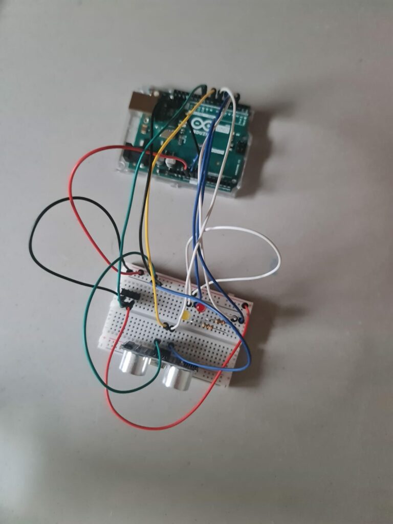
For this weeks assignment I wanted to create a parking space detector system that assists drivers in finding available parking spots quickly and efficiently. It utilizes an ultrasonic sensor to detect the presence of vehicles in front of designated parking spaces. Through a series of LEDs, the system provides visual feedback to indicate the availability of parking spots to approaching drivers.

Technical Details:

I have used the ultrasonic sensor, after looking into it – this sensor emits ultrasonic waves and measures the time it takes for the waves to bounce back after hitting an object. Which means that it can be used to determines the distance of the object from its position.

LED Indicators

Connected the anode (longer leg) of each LED to digital pins 8, 9, and 10 on the microcontroller respectively.

Connected the cathode (shorter leg) of each LED to ground through a resistor ( 220Ω to 330Ω) to limit current and prevent damage.

Green LED: Indicates a vacant parking space. When the distance measured by the ultrasonic sensor exceeds a certain threshold (indicating no object is present), the green LED lights up, signaling to approaching drivers that the parking spot is available for use.

  • Red LED: Represents a partially occupied parking space. If the distance measured falls within a predefined range, suggesting the presence of a vehicle but with some space remaining, the red LED illuminates. This warns drivers that the space is partially occupied and may not be suitable for parking larger vehicles.
  • Blue LED: Signals a fully occupied or obstructed parking space. When the measured distance is very close to the sensor, indicating a fully occupied space or an obstruction such as a wall or pillar, the blue LED turns on. This prompts drivers to avoid attempting to park in the space to prevent potential collisions or damage to vehicles.
  • Ultrasonic Sensor:
    • Trig Pin: Connected  to digital pin 2 on the microcontroller.
    • Echo Pin: Connected to digital pin 3 on the microcontroller.
    • Vcc: Connected to 5V.
    • GND: Connected to ground.
  • Button:
    • One side connects to digital pin 13 on the microcontroller.
    • The other side connects to ground.
Code
// Define LED pins
int ledPin[3] = {8, 9, 10};

// Define Ultrasonic sensor pins
const int trigPin = 2; // or any other unused digital pin
const int echoPin = 3; // or any other unused digital pin

const int buttonPin = 13;
int buttonState = HIGH;
int lastButtonState = HIGH;
long lastDebounceTime = 0;
long debounceDelay = 50;
int pushCounter = 0;
int numberOfLED = 3;

void setup() {
  pinMode(buttonPin, INPUT);
  digitalWrite(buttonPin, HIGH); // Activate internal pull-up resistor
  
  // Set up LED pins
  for (int i = 0; i < numberOfLED; i++) {
    pinMode(ledPin[i], OUTPUT);
  }
  
  // Set up Ultrasonic sensor pins
  pinMode(trigPin, OUTPUT); // Sets the trigPin as an OUTPUT
  pinMode(echoPin, INPUT);  // Sets the echoPin as an INPUT
}

void loop() {
  int reading = digitalRead(buttonPin);

  // Check if the button state has changed
  if (reading != lastButtonState) {
    // Reset the debounce timer
    lastDebounceTime = millis();
  }

  // Check if the debounce delay has passed
  if ((millis() - lastDebounceTime) > debounceDelay) {
    // If the button state has changed, update the button state
    if (reading != buttonState) {
      buttonState = reading;

      // If the button state is LOW (pressed), increment pushCounter
      if (buttonState == LOW) {
        pushCounter++;
      }
    }
  }

  // Update the last button state
  lastButtonState = reading;

  // Turn off all LEDs
  for (int i = 0; i < numberOfLED; i++) {
    digitalWrite(ledPin[i], LOW);
  }

  // Perform Ultrasonic sensor reading
  long duration, distance;
  digitalWrite(trigPin, LOW);
  delayMicroseconds(2);
  digitalWrite(trigPin, HIGH);
  delayMicroseconds(10);
  digitalWrite(trigPin, LOW);
  duration = pulseIn(echoPin, HIGH);
  distance = (duration * 0.0343) / 2; // Calculate distance in cm

  // Perform actions based on distance measured
  if (distance < 10) {
    // Turn on first LED
    digitalWrite(ledPin[0], HIGH);
  } else if (distance < 20) {
    // Turn on second LED
    digitalWrite(ledPin[1], HIGH);
  } else if (distance < 30) {
    // Turn on third LED
    digitalWrite(ledPin[2], HIGH);
  }

  // Delay before next iteration
  delay(100); // Adjust as needed
}
Circuit

Video of the Final Circuit

Reference

I watched this video to get familiar to the ultrasonic sensor.