Code Link:
https://github.com/lonussss/Intro-to-IM/blob/main/week9_assignment.ino
Concept:
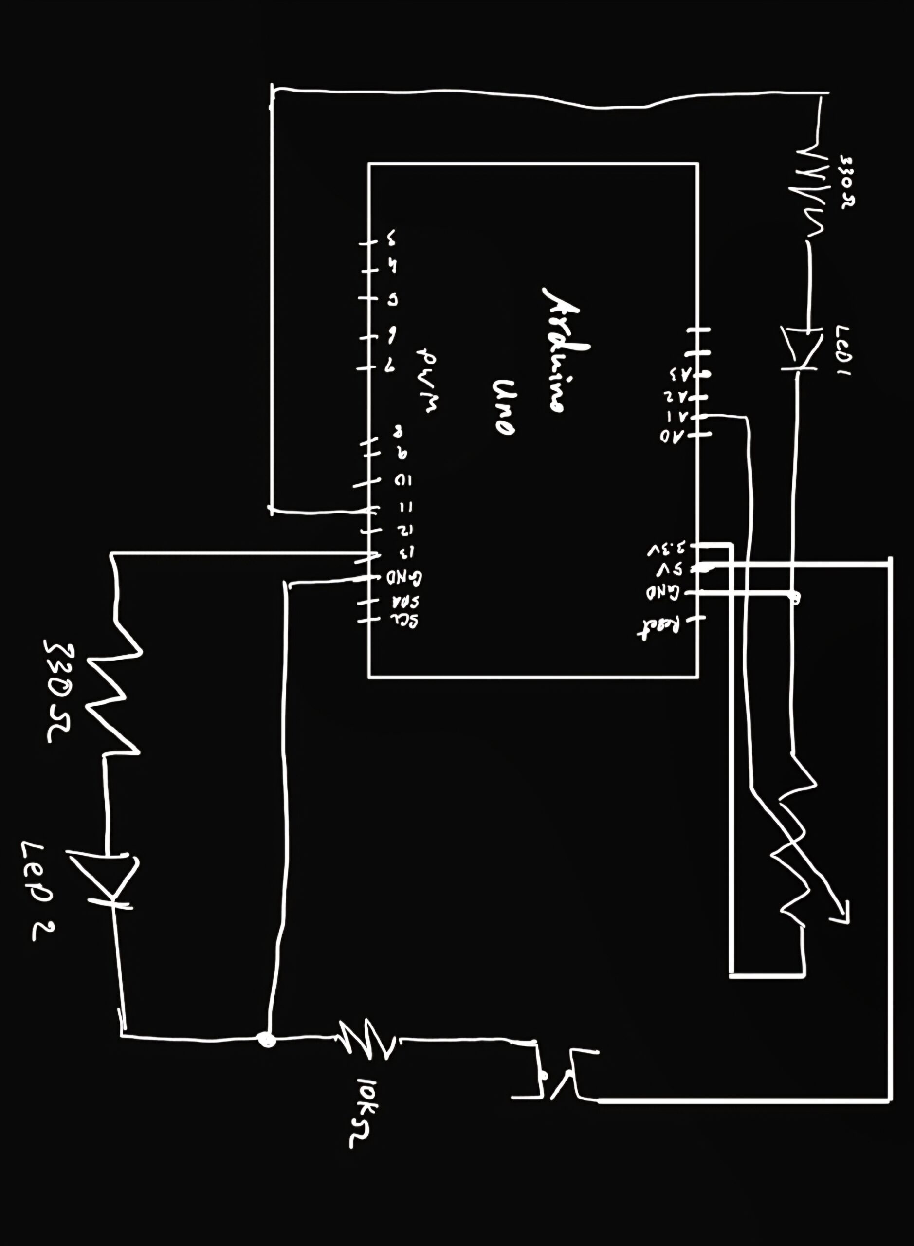
My concept for this week’s assignment was pretty simple, I wanted a button activated LED to power trigger another LED, that is triggered by a light sensor.
Code Highlight:
void loop() {
  // put your main code here, to run repeatedly:
int buttonState = digitalRead(A1);
int sensorValue = analogRead(A2);

if (buttonState == HIGH )
{
  digitalWrite(13, HIGH);
  //Serial.println("button pressed");
} else{
  digitalWrite(13, LOW);

}


sensorValue = constrain(sensorValue, 300,350);

brightness = map(sensorValue,300,350,0,255);
Serial.println(sensorValue);

analogWrite(redLed,brightness);

delay(30);
}
the loop part of the codes holds the code for both the digital button-activated led, and the light sensor led. I had adjusted the sensor values to vary between 300 to 350, since that was magnitude of change that I had observed through the serial monitor that the LED had on the environment.
Video Demonstration:
Problems fixed and future improvements:
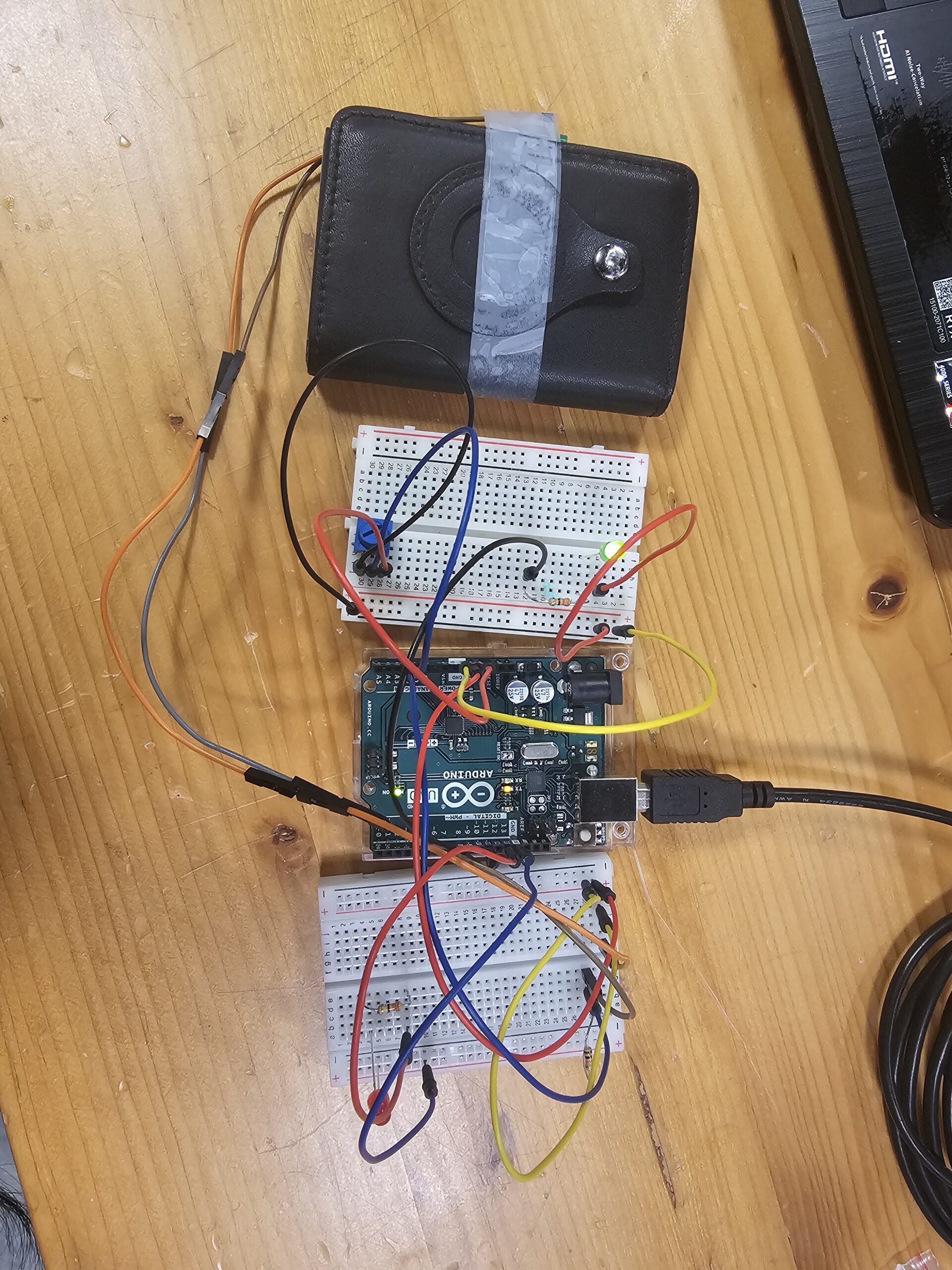
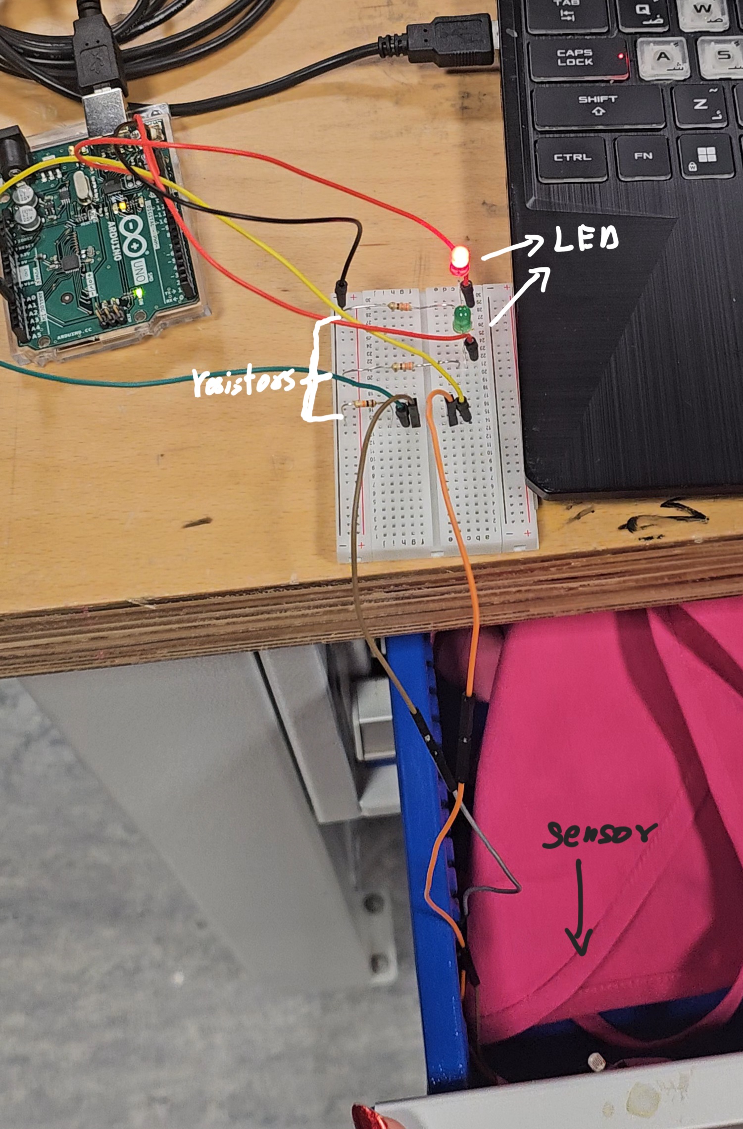
I initially just had the led wired, however, the light sensor was inconsistent in detecting a different of whether the led was turned on or not, so I had to improvise a bit a built a little paper tent to go over the button activated led and the light sensor, doing this allowed the light sensor to clearly detect a change in the brightness of the environment.
Although I have 2 leds now, some future improvements to make this more useful would be connecting something else like a motor or speaker to the light sensor, so that the button pressed could affect more things and not just 2 leds.