Week 12: Khalifa Alshamsi, Snehil Ahuja, and Saeed Lootah

  1. Make something that uses only one sensor  on Arduino and makes the ellipse in p5 move on the horizontal axis, in the middle of the screen, and nothing on Arduino is controlled by p5
  2. Make something that controls the LED brightness from p5

For these two exercises, we made it so that the potentiometer that is connected to the Arduino controls the LED on the breadboard and the ellipse in the p5 sketch in the middle of the screen, and also when the keyboard keys are pressed up or down it would change the brightness of that LED light.

P5.js Code:

let LEDbrightness = 0;

function setup()
{
  createCanvas(400, 400);
}


function textDisplay() //display text in the starting
{
  text("PRESS SPACE TO START SERIAL PORT", width/2 - 109, height/2 - 5);
}

function draw()
{

  background(255);

  if (serialActive) //if serial is active
  {
    text("CONNECTED", width/2 - 27, height/2 - 5);
    text("PRESS UP/DOWN ARROW KEYS TO CHANGE BRIGHTNESS!", width/2 -180, height/2 + 15);
  }
  else
  {
    textDisplay();
  }
}


function keyPressed() //built in function
{
  if (key == " ") //if space is pressed then
  {
    setUpSerial(); //setup the serial
  }
  else if (keyCode == DOWN_ARROW)
  {
    if (LEDbrightness != 0)
    {
      LEDbrightness = LEDbrightness - 20;
    }
  }
  else if (keyCode == UP_ARROW)
  {
    if (LEDbrightness != 250)
    {
      LEDbrightness = LEDbrightness + 20;
    }
  }

}

//callback function
function readSerial(data)
{
    let sendToArduino = LEDbrightness + "\n"; //add the next line to dimness counter
    writeSerial(sendToArduino); //write serial and send to arduino
}

Arduino Code:

const int LED_PIN = 5;
int brightness = 0;

void setup()
{
  Serial.begin(9600);

  pinMode(LED_PIN, OUTPUT);

  while (Serial.available() <= 0)
  {
    Serial.println("CONNECTION STARTED");
  }
}
void loop()
{

    while (Serial.available())
    {
      brightness = Serial.parseInt();
      Serial.println(brightness);

      if (Serial.read() == '\n')
      {
        analogWrite(LED_PIN, brightness);
      }
    }
}

Video and Photos for Exercise 1:

For exercise 1, since we were just getting started, the main problem was understanding how serial communication works. We had some kind of idea when it was being presented to us, but until we started working, we didn’t really know. Other than that, there weren’t really any specific challenges. We didn’t need to use the trim() method, we had one value coming in from the Arduino, which was the potentiometer, and we had some troubles at first, but once we casted it as an integer value (it’s received as a string), then mapped it to the width and made the mapped value the x-position of the ellipse the project was done.

You’ll notice in the image that there’s an LED. The LED was there to test whether or not there was power being outputted from the potentiometer. We added it while we were debugging.

Video and Photos for Exercise 2:

Like the previous exercise there was only one value that was being communicated between the arduino and the p5js code so it was fairly simple. The hard part was just getting it such that tapping it reduced the brightness value by a specific amount and increasing it by a certain amount.

3. Take the gravity wind example and make it so every time the ball bounces one led lights up and then turns off, and you can control the wind from one analog sensor

For this exercise, the code creation uses p5, where physics principles like gravity and wind influence the ellipse’s motion. The sketch also communicates with the Arduino, which can control an LED based on the object’s motion, specifically if it bounces.

P5.js Code:

let dragForce = 0.99;
let mass = 20;
let ledState = 0;
let velocity;
let gravity;
let position;
let acceleration;
let wind;
let force;
let bounced = false;


function setup() {
  createCanvas(640, 480);
  textSize(18);
  position = createVector(width / 2, 0);
  velocity = createVector(0, 0);
  acceleration = createVector(0, 0);
  gravity = createVector(0, 0.3 * mass);
  wind = createVector(0, 0);
}

function draw() {
  background(0,40);
  // background(0);
  // background(255);

  if (!serialActive) {
    fill(255);
    text("Press Space Bar to select Serial Port", 20, 30);
  } else {

    noStroke();
    force = p5.Vector.div(wind, mass);
    acceleration.add(force);
    force = 0;
    force = p5.Vector.div(gravity, mass);
    acceleration.add(force);
    force = 0;
    velocity.add(acceleration);
    velocity.mult(dragForce);
    position.add(velocity);
    acceleration.mult(0);

    ellipse(position.x, position.y, mass, mass);
    if (position.y > (height - mass / 2)-30 ) {
      velocity.y *= -0.9;
      position.y = (height - mass / 2)-30;
      ledState= 1;
      
      if (!bounced) {
        fill(255, 0, 0); // Red when just bounced
        bounced = true; // Update bounce state
      } else {
        fill(255); // White otherwise
        bounced = false; // Reset bounce state
      }
    } else {
      ledState = 0;
    }
  
    
  }

  rect(0,height-30,width,30);
  
}

function keyPressed() {
  if (key == " ") {
    // important to have in order to start the serial connection!!
    setUpSerial();
  }
}

function readSerial(data) {
  if (data != null) {
    // make sure there is actually a message
    // split the message
    let fromArduino = split(trim(data), ",");
    // if the right length, then proceed
    if (fromArduino.length == 1) {
      let windCurrent = int(fromArduino[0]);
      wind.x = map(windCurrent, 0, 1023, -1, 1);
    }

    //////////////////////////////////
    //SEND TO ARDUINO HERE (handshake)
    //////////////////////////////////
    let sendToArduino = ledState + "\n";
    writeSerial(sendToArduino);
  }
}

Arduino code:

int ledPin = 5;
int potPin = A0;

void setup() {
  Serial.begin(9600);

  pinMode(LED_BUILTIN, OUTPUT);

  // Outputs on these pins
  pinMode(ledPin, OUTPUT);

  // start the handshake
  while (Serial.available() <= 0) {
    digitalWrite(LED_BUILTIN, HIGH); // on/blink while waiting for serial data
    Serial.println("0"); // send a starting message
    delay(300);            // wait 1/3 second
    digitalWrite(LED_BUILTIN, LOW);
    delay(50);
  }
}

void loop() {
  // wait for data from p5 before doing something
  while (Serial.available()) {
    digitalWrite(LED_BUILTIN, HIGH); // led on while receiving data

    int right = Serial.parseInt();
    if (Serial.read() == '\n') {
      digitalWrite(ledPin, right);
      int potValue = analogRead(potPin);
      delay(5);
      Serial.println(potValue);
    }
  }
}

Video and Photos for Exercise 3:

Understandably, this was the hardest of the 3. We first manipulated the code given to us (which had the wind and ball code). We changed the wind global variable in much the same way as the first exercise: The potentiometer value was mapped to the wind variable. The hard part was the bouncing. There was a point during the exercise where we felt we had written everything correctly, and after going through the code together, we couldn’t see what was wrong. We made a variable called bounced and had it such that inside of the if statement, which would be called upon when the ball was supposed to bounce, the variable would be the opposite of what it was previously (if true then false, if its false then true). We then realized we were initializing the bounced variable inside of the draw function. We made it a global variable, and then it worked.

Week 12 Reading – Shaikha AlKaabi

This week’s reading, “Design Meets Disability,” examines the relationship between design and disability, challenging the traditional view that disability aids should be discreet and practically invisible. The book argues for a new approach that balances functionality with aesthetic appeal, similar to how glasses have evolved from a medical necessity to a fashion statement. It emphasizes that disability aids should not only serve practical purposes but also make positive aesthetic statements.

The text highlights examples like the Eameses’ leg splints, initially designed for functionality but now celebrated for their innovative design. This shows the potential for disability design to extend beyond basic functionality and influence broader design disciplines.

The book critiques cultural and social norms that favor invisibility in disability aids and advocates for designs that are empowering and expressive. It explores how products like glasses have successfully become both functional and fashionable, suggesting a similar potential for other disability aids.

To conclude, “Design Meets Disability” calls for a reevaluation of design principles in the context of disability. It argues for designs that are not only functional but also aspirational and culturally relevant, aiming to reflect the diversity of users and contribute to a more inclusive society where design enhances individual identity and expression.

Week 12 Reading Response: Designing for Disability

Designs, designs, designs. Throughout our whole life everything we see was designed and adapted for us (humans) to be used in the most practical and (sometimes) efficient way. The thing is that, all of these things more often than note don’t take into account people with disabilities.

One of the problems for that, as mentioned in the reading, is that people with disabilities cannot be exactly grouped the same as an “average human”. What I mean by that is the design process for items used by people with disabilities needs to be more tailored individually, because these people, even though they might be diagnosed with the same type of disability, very often have different ways of experiencing the world and “fighting” through the disability.

On the bright side, recently, I have seen more applications and Programs/ Games which seamlessly incorporate designs which take these people into account. One example is the game Fortnite. Fortnite has a special menu in the Video Settings where you can change the colors based on the Persons Type and Level of daltonism. This changes all the colors on the screen and allows for the player to have a normal playing experience. Another feature this game has is the Sound circle, which is a circle which appears around the character displaying where sounds come from, so this takes people with hearing disabilities into account.

It has also been a pleasure to be a witness of an IM Project last semester from one of my friends. He made a small machine which would let users hear a word and then learn the Braille alphabet. I thought this was a very nice design, with small pads that mimic the little dots from the Alphabet.

I feel like in the future we need to contribute to the community even more by adding more designs which would further improve the life of people with disabilities. The change starts from US!


Week 12 Assignment – Rashed and Jana

Exercise 1: 

P5 code:

let rVal = 0;
let alpha = 255;
let left = 0; // True (1) if mouse is being clicked on left side of screen
let right = 0; // True (1) if mouse is being clicked on right side of screen

function setup() {
createCanvas(640, 480);
textSize(18);
}

function draw() {
// one value from Arduino controls the background's red color
background(255)

// the other value controls the text's transparency value
fill(255, 0,0)

if (!serialActive) {
text("Press Space Bar to select Serial Port", 20, 30);
} else {
text("Connected", 20, 30);
// Print the current values
text('rVal = ' + str(rVal), 20, 50);
text('alpha = ' + str(alpha), 20, 70);
}

// click on one side of the screen, one LED will light up
// click on the other side, the other LED will light up
if (mouseIsPressed) {
if (mouseX > rVal-50 && mouseX < rVal+50 && mouseY > height/2-50 && mouseY < height/2+50) {
right = 1;
}
} else {
right = 0;
}
ellipse(rVal, height/2, 50,50)
}

function keyPressed() {
if (key == " ") {
// important to have in order to start the serial connection!!
setUpSerial();
}
}

// This function will be called by the web-serial library
// with each new line of data. The serial library reads
// the data until the newline and then gives it to us through
// this callback function
function readSerial(data) {
////////////////////////////////////
//READ FROM ARDUINO HERE
////////////////////////////////////

if (data != null) {
// make sure there is actually a message
// split the message
let fromArduino = split(trim(data), ",");
// if the right length, then proceed
if (fromArduino.length == 2) {
// only store values here
// do everything with those values in the main draw loop

// We take the string we get from Arduino and explicitly
// convert it to a number by using int()
// e.g. "103" becomes 103
rVal = int(fromArduino[0]);
alpha = int(fromArduino[1]);
}

//////////////////////////////////
//SEND TO ARDUINO HERE (handshake)
//////////////////////////////////
let sendToArduino = left + "," + right + "\n";
writeSerial(sendToArduino);
}
}


We did not face any big issue in this part. We just added the ellipse and changed its position to rVal, height/2.

Video:

Exercise 2: 

P5 code:

let rVal = 0;
let alpha = 255;
let left = 0; // True (1) if mouse is being clicked on left side of screen
let right = 0; // True (1) if mouse is being clicked on right side of screen

function setup() {
createCanvas(640, 480);
textSize(18);
}

function draw() {
// one value from Arduino controls the background's red color
background(map(rVal, 0, 1023, 0, 255), 255, 200);

// the other value controls the text's transparency value
fill(255, 0, 255, map(alpha, 0, 1023, 0, 255));

if (!serialActive) {
text("Press Space Bar to select Serial Port", 20, 30);
} else {
text("Connected", 20, 30);
// Print the current values
text('rVal = ' + str(rVal), 20, 50);
text('alpha = ' + str(alpha), 20, 70);
}


function keyPressed() //built in function
{
if (key == " ") //if space is pressed then
{
setUpSerial(); //setup the serial.
}
else if (keyCode == DOWN_ARROW)
{
if (right != 0)
{
right = right - 20;
}
}
else if (keyCode == UP_ARROW)
{
if (right != 250)
{
right = right + 20;
}
}
}
}

// This function will be called by the web-serial library
// with each new *line* of data. The serial library reads
// the data until the newline and then gives it to us through
// this callback function
function readSerial(data) {
////////////////////////////////////
//READ FROM ARDUINO HERE
////////////////////////////////////

if (data != null) {
// make sure there is actually a message
// split the message
let fromArduino = split(trim(data), ",");
// if the right length, then proceed
if (fromArduino.length == 2) {
// only store values here
// do everything with those values in the main draw loop

// We take the string we get from Arduino and explicitly
// convert it to a number by using int()
// e.g. "103" becomes 103
rVal = int(fromArduino[0]);
alpha = int(fromArduino[1]);
}

//////////////////////////////////
//SEND TO ARDUINO HERE (handshake)
//////////////////////////////////
let sendToArduino = left + "," + right + "\n";
writeSerial(sendToArduino);
}
}


Arduino code for Exercise 1 and 2:

int leftLedPin = 2;
int rightLedPin = 5;

void setup() {
// Start serial communication so we can send data
// over the USB connection to our p5js sketch
Serial.begin(9600);

// We'll use the builtin LED as a status output.
// We can't use the serial monitor since the serial connection is
// used to communicate to p5js and only one application on the computer
// can use a serial port at once.
pinMode(LED_BUILTIN, OUTPUT);

// Outputs on these pins
pinMode(leftLedPin, OUTPUT);
pinMode(rightLedPin, OUTPUT);

// Blink them so we can check the wiring
digitalWrite(leftLedPin, HIGH);
digitalWrite(rightLedPin, HIGH);
delay(200);
digitalWrite(leftLedPin, LOW);
digitalWrite(rightLedPin, LOW);


// start the handshake
while (Serial.available() <= 0) {
digitalWrite(LED_BUILTIN, HIGH); // on/blink while waiting for serial data
Serial.println("0,0"); // send a starting message
delay(300); // wait 1/3 second
digitalWrite(LED_BUILTIN, LOW);
delay(50);
}
}

void loop() {
// wait for data from p5 before doing something
while (Serial.available()) {
digitalWrite(LED_BUILTIN, HIGH); // led on while receiving data

int left = Serial.parseInt();
int right = Serial.parseInt();
if (Serial.read() == '\n') {
digitalWrite(leftLedPin, left);
digitalWrite(rightLedPin, right);
int sensor = analogRead(A0);
delay(5);
int sensor2 = analogRead(A1);
delay(5);
Serial.print(sensor);
Serial.print(',');
Serial.println(sensor2);
}
}
digitalWrite(LED_BUILTIN, LOW);
}


Challenges:

We tried to get the light to decrease its brightness every time the person would click on the left side of the screen and for the brightness to increase whenever the person clicks on the right side of the screen. The code was correct, but for some reason it was not working. So, it might be something with the bulb or the Arduino itself. However, the light does take around 4 clicks on both sides of the screen to turn off or on so, we would consider that a success.

Video:

Exercise 3: 

P5 code:

let dragForce = 0.99;
let mass = 20;
let ledState = 0;
let velocity;
let gravity;
let position;
let acceleration;
let wind;
let force;
let bounced = false;


function setup() {
createCanvas(640, 480);
textSize(18);
position = createVector(width / 2, 0);
velocity = createVector(0, 0);
acceleration = createVector(0, 0);
gravity = createVector(0, 0.3 * mass);
wind = createVector(0, 0);
}

function draw() {

background(255);

if (!serialActive) {
text("Press Space Bar to select Serial Port", 20, 30);
} else {
text("Connected", 20, 30);

noStroke();
force = p5.Vector.div(wind, mass);
acceleration.add(force);
force = 0;
force = p5.Vector.div(gravity, mass);
acceleration.add(force);
force = 0;
velocity.add(acceleration);
velocity.mult(dragForce);
position.add(velocity);
acceleration.mult(0);

ellipse(position.x, position.y, mass, mass);
if (position.y > (height - mass / 2)-30 ) {
velocity.y *= -0.9;
position.y = (height - mass / 2)-30;
ledState= 1;

if (!bounced) {
fill('blue'); // Red when just bounced
bounced = true; // Update bounce state
} else {
fill('red'); // White otherwise
bounced = false; // Reset bounce state
}
} else {
ledState = 0;
}


}

rect(0,height-30,width,30);

}

function keyPressed() {
if (key == " ") {
// important to have in order to start the serial connection!!
setUpSerial();
}
}
function readSerial(data) {
if (data != null) {
// make sure there is actually a message
// split the message
let fromArduino = split(trim(data), ",");
// if the right length, then proceed
if (fromArduino.length == 1) {
let windCurrent = int(fromArduino[0]);
wind.x = map(windCurrent, 0, 1023, -1, 1);
}

//////////////////////////////////
//SEND TO ARDUINO HERE (handshake)
//////////////////////////////////
let sendToArduino = ledState + "\n";
writeSerial(sendToArduino);
}
}


Arduino code:

int ledPin = 10;
int potPin = A0;

void setup() {
Serial.begin(9600);

pinMode(LED_BUILTIN, OUTPUT);

// Outputs on these pins
pinMode(ledPin, OUTPUT);

// start the handshake
while (Serial.available() <= 0) {
digitalWrite(LED_BUILTIN, HIGH); // on/blink while waiting for serial data
Serial.println("0"); // send a starting message
delay(300); // wait 1/3 second
digitalWrite(LED_BUILTIN, LOW);
delay(50);
}
}

void loop() {
// wait for data from p5 before doing something
while (Serial.available()) {
digitalWrite(LED_BUILTIN, HIGH); // led on while receiving data

int right = Serial.parseInt();
if (Serial.read() == '\n') {
digitalWrite(ledPin, right);
int potValue = analogRead(potPin);
delay(5);
Serial.println(potValue);
}
}
}


Challenges:

Everything went smoothly when writing the code. However, when we would click the play button to see the sketch, it would give us the error: “setUpArduino is not defined”. So, we spent countless minutes searching for something that was not there. After looking at the professors week 12 example on serial connection, we realized that we have forgotten the tab that would connect P5 to Arduino. So we just added that and it worked.

Video:

very very cute :3

Final Project Proposal

HAILSTORM HAIVOC CONTINUED

Concept for the project

For my final project, I am building on my midterm project, which involves a game where players dodge falling hail. Initially, I had envisioned this game with a car maneuvering to avoid the hail, but the concept became too complex. Through trial and error, I simplified the gameplay to where players now use the mouse click to move the car away from the hail. This feature unexpectedly also allows control over another sprite, adding a unique twist to the gameplay. Taking this project to the next level, I plan to integrate an arcade button to start and re-start the game and a toy car that players can manipulate/move to control the game car on the screen through a sensor. Differing from the midterm which was consistently playing, my game has an end after a couple seconds of playing where the player would have won and arrived home safely from the storm, and this would enhance the interactive experience and depth of the game.

Description of what your Arduino program will do with each input and output and what it will send to and/or receive from P5:

  1. Inputs:
    • HC-SR04 Ultrasonic Sensor: This sensor will measure the distance of an object from it. It uses two pins, TRIG and ECHO, to send out ultrasonic waves and measure the time it takes for the echo to return.
    • Arcade Button: The button will act as a simple digital input, where pressing the button changes its state from LOW to HIGH.
  2. Outputs:
    • Serial Data to P5: The Arduino program will continuously send two pieces of data to the P5 sketch via the serial port:
      • Distance measured by the ultrasonic sensor, translated into a value that indicates the position of the car on the screen, hopefully when the toy car is moved left (close to the sensor it will move the car on screen left) and vise versa.
      • The state of the arcade button to control game states (start and restart).

Description of what P5 program will do and what it will send to and/or receive from Arduino:

As of my game, I don’t think P5 is going to send anything to Arduino other than:  Serial Data from Arduino: The P5 sketch receives the distance and button state as a serialized string. Game Controls: Based on the received data, the P5 sketch adjusts the position of the car on the screen and manages the game state (starting and restarting).

Final Final Project Proposal – Week 12

Safe Russian Roulette

Introduction

After having done a bit more research and some more ideation I am now sure of what I am going to create exactly. Of course there may be some changes down the road but the project should be at least 90% like what I’m going to outline here.

Inspiration

I originally had this idea before the midterm and it was going to be my midterm project but instead I changed it to the Mexican Standoff game. But, what I really wanted to do for both of these projects is make a game or anything that was interactive but that allowed for at least two people to enjoy the experience together.

I had been inspired by the indie game Buckshot Roulette as well. It’s a game where the player plays against a strange looking dealer who has lives and so does the player and the lives are represented by lightning bolts and there are abilities as well which makes the game more tactical. I wanted to almost recreate the game or at least the aesthetic but for now I will not do the abilities since I need to at least finish the foundation, i.e. just normal Russian Roulette.

The lightning bolts representing the lives of both the dealer and the player were done because each of them could be revived with a defibrillator. It was the lightning bolts themselves which lead to me having the idea of a player receiving an electric shock.

Then having the lives and a little menu on the side of the table inspired me to have a p5js sketch which can has a similar aesthetic.

How Russian Roulette works
& How this game will work

In the real game of Russian Roulette a revolver would be loaded with one live round and then the rest would either be empty or blanks.

In Safe Russian Roulette there will also be at least one live “round” and the rest are blanks, totaling 6 rounds. Depending on the difficulty chosen there will be between 1-5 rounds that are live. The names of the difficulties in ascending order are Standard (1 live round), Hard (1-2 live round), Harder (1-3 live rounds), Nearly Impossible (2-4 live rounds), Masochist (3-5 live rounds)

There will be 2 buttons for each player to press to either shoot themselves or the other. When the player shoots themselves they may either shock themselves or it may be a blank. If its a live round they lose and if its a blank they get a second turn which means its more likely that the next round will be live and therefore more likely that they will win if they shoot the other player. Each player has one life. Basically its a game of chance.

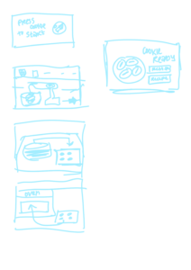
Before the players start shocking each other they will be greeted with a start page. There will be a potentiometer or knob of some kind and a button and together the user can select different options that are displayed using p5js. Options such as difficulty and retry.

There will also be some kind of lights that flash in a certain way which are in the middle of the table. It will display the number of live and blank rounds at the beginning (it can change color, red = live, white = blank) then, depending on the difficulty, it will either disappear completely, or it will show the number of rounds remaining but it will never show the number of live or blank rounds left, just the number of rounds left at most.

Then after one of the players lose it will indicate on the play screen who won and who lost and then ask the players if they want to play again or not. Also, during the game while the players are playing it will indicate the difficulty that the players are playing at so that others can see and in case they forgot.

Redha Final Project Update – “Selfies for Two <3"

Upon developing the concept for my final project, I have decided to incorporate a more communal element into my work as a means to utilise internet culture to physically bring people together and create tangible memories.

I will be using the same image classification process as described in my initial post but will create my own machine learning model using Google’s Teachable Machine. Doing this will enable the object classification to be more accurate and specific, ensuring a smoother interaction between users and the project. When gathering the sample images for this, I will make sure that the environment and framing is as close as possible to what the program will see on-site in order to ensure its accuracy while being open to the public.

In terms of the communal aspect, the project will require two phones (and therefore two people) to be detected by the program in order to generate the digital mirror. In making this choice, I hope to utilise the tendency we have to take photographs of ourselves as a means to bring us closer with our friends and loved ones, thus replacing an otherwise self-centred process with one that focuses on interpersonal connection. In order to compliment and emphasise this point, I will generating an ASCII-style digital mirror which fills the thresholded space with the text-heart emoticon ‘<3’. Not only does this link to the theme of interpersonal connection, it also refers back to the theme of internet culture which was ultimately the influence behind my project.


Raya Tabassum: Reading Response 7

“Design Meets Disability” provides a rich examination of how design intersects with disability, with a focus on both the historical context and contemporary innovations in the field. It delves into specific examples like eyewear, hearing aids, and prosthetics, and underscores a cultural shift from viewing these items merely as medical aids to considering them as fashion statements and expressions of personal identity.

As someone interested in design, I find the intersection of fashion and functionality particularly fascinating. The way eyewear evolved from a stigmatized medical device to a stylish accessory exemplifies how cultural perceptions of disability and assistive devices can shift dramatically. This shift challenges us to think about other devices in the same light. Could hearing aids or prosthetics become similarly fashionable? This idea encourages a reconsideration of what we define as “normal” and pushes the boundaries of inclusivity in design. From my perspective, embracing design innovation in disability aids not only enhances functionality but also boosts the self-esteem of users. If more designers viewed these aids as opportunities for creative expression, we might see a broader acceptance and desire for these products, much like what happened with eyeglasses.

Week 12 : Pi Final Project Progress

As for the progress on my final project this week, the body frame is already built. I am still assembling the legs (They take time).

Also, in terms of the electronics, I need to order an additional Li-Po battery and a voltage converter to supply the power to the servo motors.

Also, for the cardboard castle above the walker, I began generating the textures in Midjourney. Still in the progress of assembling.

I unfortunately lost my ESP32 chip, so need to re-order it again.

Raya Tabassum: Final Project Concept & Progress

Finalized Concept for the Project:
“Interactive Musical Garden” is an immersive installation combining technology and nature, designed to create a harmonious interaction between physical and digital realms. The project features a set of 3D-printed roses, each equipped with capacitive touch sensors and LEDs, laid out on a cardboard garden surface to mimic a garden. Interacting with these roses triggers specific musical tones and stimulates the blooming of virtual flowers on a screen, managed via a P5 sketch. This setup aims to explore the symbiotic relationship between touch-based interactions and visual-audio feedback, enhancing the user’s sensory experience through art and technology.

Design and Description of the Arduino Program:

Inputs: The Arduino will use capacitive touch sensors placed beneath each 3D-printed rose. These sensors detect the presence and duration of touch.
Outputs: Corresponding to each sensor, LEDs under the roses light up when a touch is detected. Additionally, the Arduino will send serial data to the P5 sketch indicating which rose was touched.

Interactive Elements:

Visual Outputs: The P5 sketch will display a dynamic garden where each touch on a physical rose causes a new type of flower to bloom at random positions on the screen.
Audio Feedback: Different musical tones are played corresponding to which rose is touched, enhancing the multisensory experience.

User Testing Goals:

Usability: Assess the ease of interaction and intuitiveness of the touch interfaces.
Responsiveness: Measure the system’s responsiveness and the synchronization between physical touches and digital responses.
Aesthetic and Sensory Feedback: Gather feedback on the visual and auditory elements to determine if they effectively enhance the user experience.

To-Dos:

  • Begin assembling the components as per the design (I couldn’t get all the sensors yet because of unavailability but as soon as I get them I’ll try to assemble everything).
  • Complete printing all the roses (I’ve one prototype now but I’d need to replicate another 3).
  • Test the initial versions of the Arduino and P5 code (I’ve written the primary codes, I’ll be repurposing the Virtual Garden p5 assignment I’d completed, and I’ve shortlisted which sound files I want to use).