If you have ever wondered how it would be to a starting DJ, this design is for you!
Alternative link to the video:https://drive.google.com/file/d/1kGo-VwdNhDPFH2HRHXRKaNn54ME_v5gZ/view?usp=sharing
Inspiration
The inspiration for this project comes from a DJ controller. We wanted to design a physical interface that would allow a range of motions by the DJ. Our focus was on an easy and intuitive design that would mimic a basic DJ controller. The 2 requirements that had to be fulfilled were a beat-making mechanism as well as a musical mechanism in which the frequency can be controlled.
Concept
In order to make our inspiration become a reality, we have decided to produce the musical notes in different frequencies of 7 tones through the buzzer while making a beat maker using the servo. A push button connected to the servo slams the handle on the wooden surface imitating the beat sound. On the other side, another button is used to switch between 7 different notes that are played in the buzzer. Potentiometer that feeds back to the buzzer allows the frequency of the tone that the buzzer is playing to go higher when it is twisted right, and lower when twisted left.
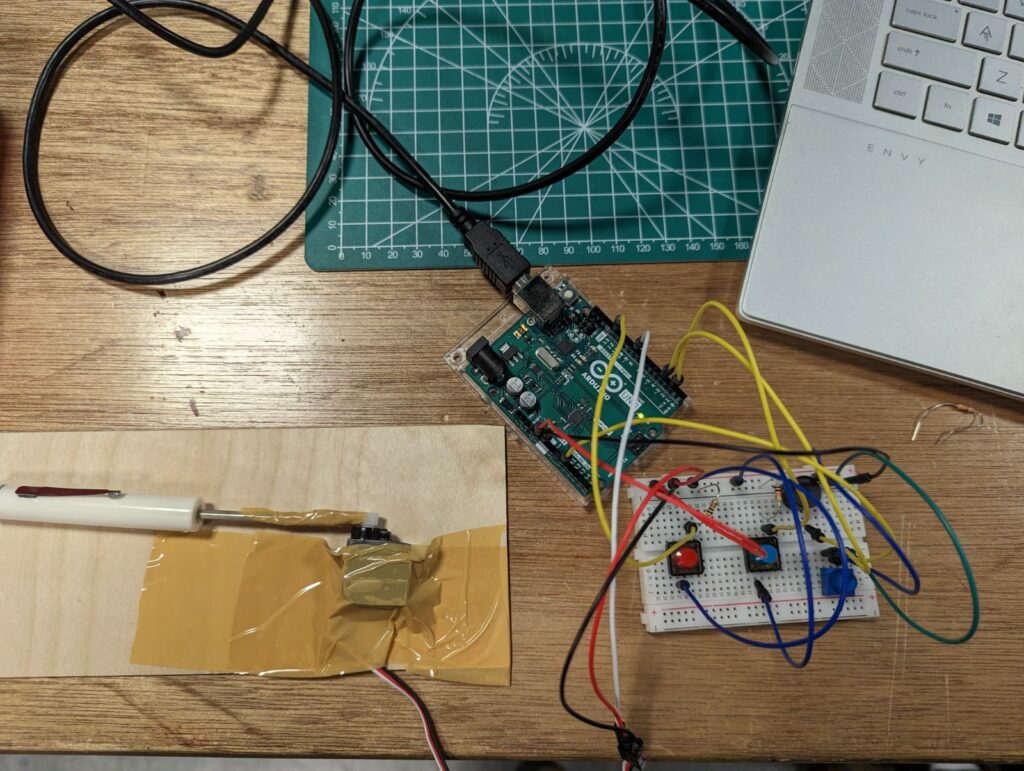
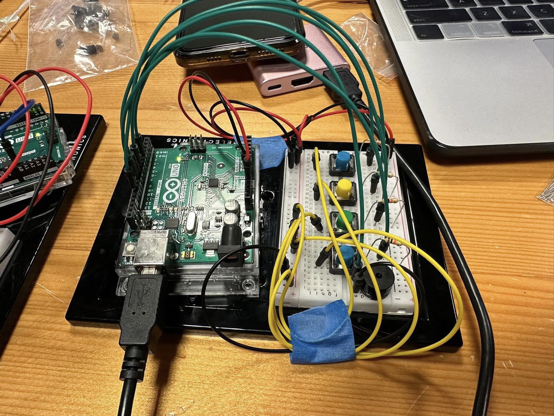
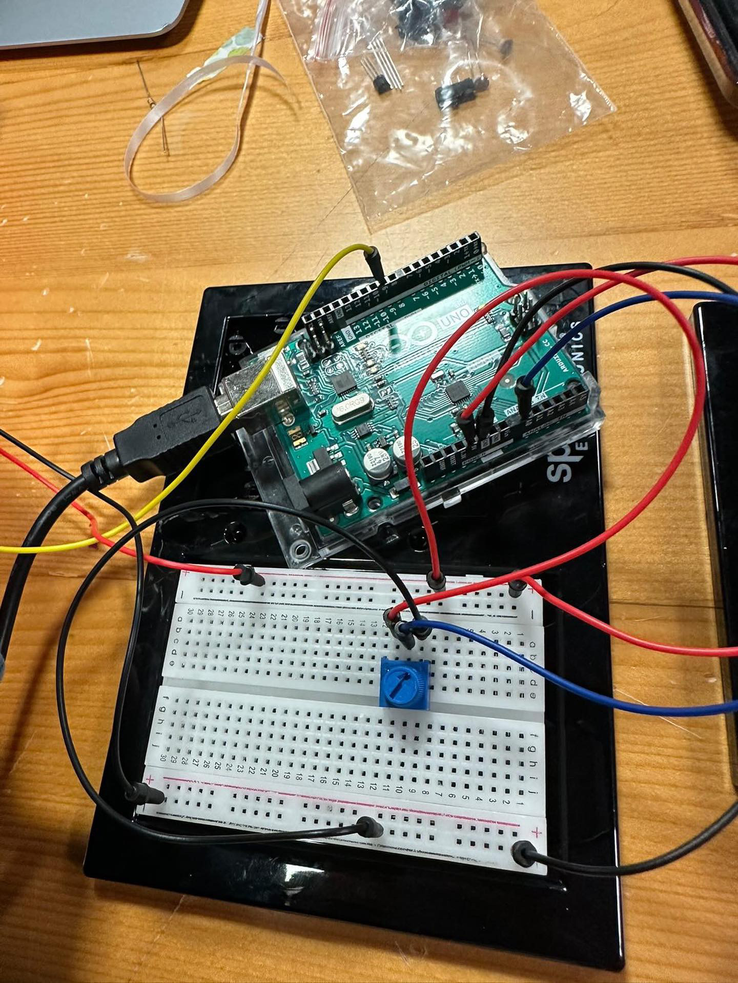
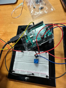
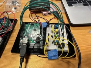
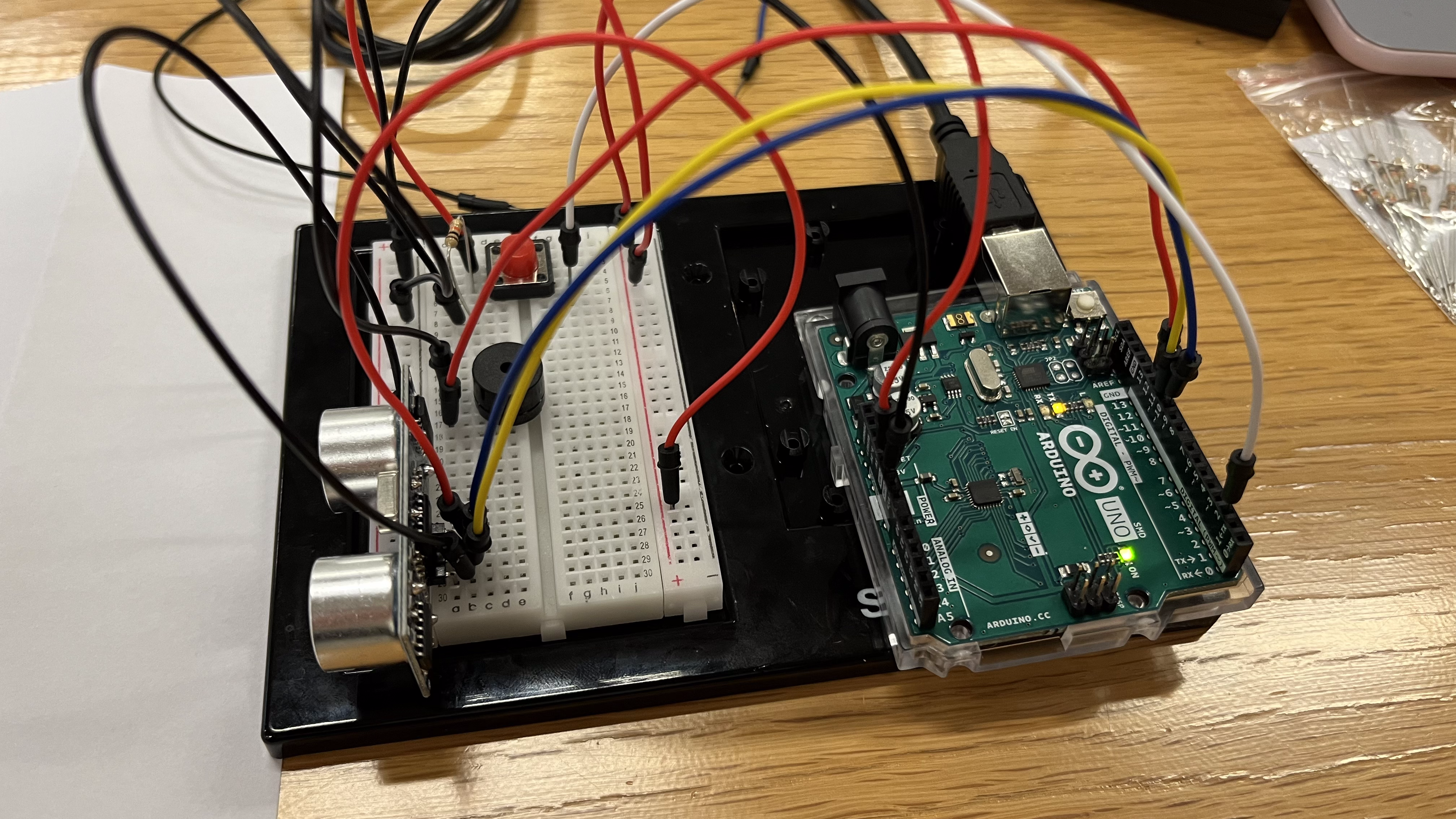
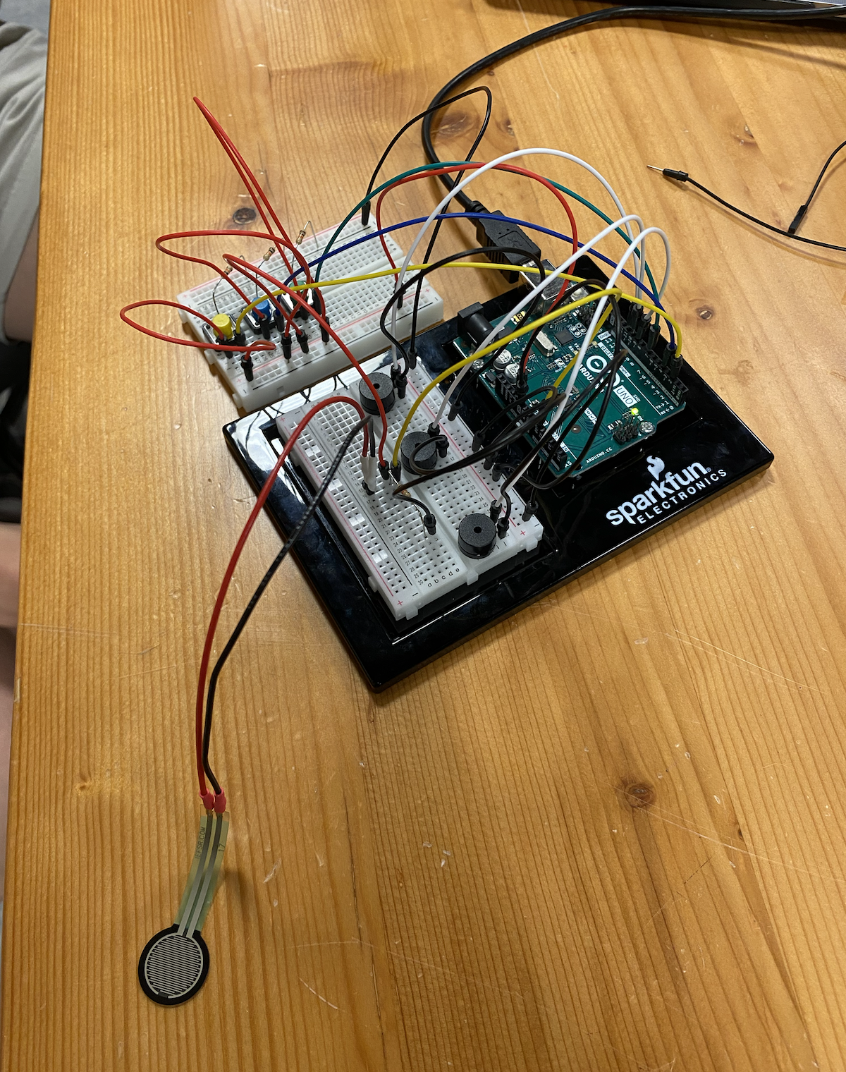
Implementation
In the implementation of the project an Arduino Uno, a servo, 2 push buttons, a buzzer, and a potentiometer are used. Servo’s rotating wing is taped to plastic handled screwdriver while the servo itself is fixed on a wooden plate.
The first push-button retains information on the occasions where it is pressed. A push that is recorded prompts the screwdriver that is connected to the rotating wing of the servo to switch from a levitating position to slam on the wooden fixation plate. The sound produced is similar to a beat sound that can be achieved from an electronic device. On the other side of the board, the push button and potentiometer both record information that changes the state of the buzzer. The buzzer is constantly creating sound. The range of sound is modeled from a piano’s octaves, and therefore there are 7 keys in 7 different octaves that can be produced from this buzzer according to the code. The frequencies of these notes are numerically written into the notes double array. The push button for the buzzer (stationed towards the right side of the breadboard) switches between the 7 notes in the order of B, C,D,E,F,G, and A. Potentiometer on the other hand, switches into higher pitch/frequency of the same note, visually can be thought of as higher octave of the same note on the piano, when turned towards the right. There are again 7 octaves possible, in which the most left position of the potentiometer is the lowest frequency the note exists in while the most right position is the highest frequency of the note.
This is the code for the said implementation.
//Include Servo Library
#include <Servo.h>

//servo
int servoPin = 9;
int pos1 = 40;
int pos2 = 110;
int dt = 100;
Servo myServo;


//pushButton for servo
int pbPin = 13;
bool pbFlag = true;

//pushButton for note change
int notePin = 2;
bool nbFlag = true;
int currNoteI = 0;
int mappedValue;

//potentiometer
int potPin = A0;

//notes array
int tones[7][7] = {{31, 62, 123, 494, 988, 1976, 3951}, {33, 65, 131, 262, 523, 1047, 2093}, {37, 73, 147, 294, 587, 1175, 2349}, {41, 82, 165, 330, 659, 1319, 2637},
  {44, 87, 175, 349, 698, 1397, 2794}, {49, 98, 196, 392, 784, 1568, 3136}, {55, 110, 220, 440, 880, 1760, 3520}
};

//buzzer
int tonePin = 4;

void moveServo() {
  delay(dt);
  myServo.write(pos1);
  delay(dt);
  myServo.write(pos2);
  delay(dt);
}

void setup() {
  // put your setup code here, to run once:
  Serial.begin(9600);

  //  setting up servos
  myServo.attach(servoPin);
  myServo.write(pos2);

  //  setting up pushbutton
  pinMode(pbPin, INPUT);

  //  setting up buzzer
  pinMode(tonePin, OUTPUT);


}

void loop() {
  // put your main code here, to run repeatedly:
  //pushbutton and servo implementation
  int pbVal = digitalRead(pbPin);
  if (pbVal == 1 && pbFlag) {
    //high
    moveServo();
    pbFlag = false;
  }
  else if (pbVal == 0) {
    pbFlag = true;
  }

  //potentiometer implementation
  int potValue = analogRead(potPin);
  mappedValue = map(potValue, 0, 1023, 6, -1);
  //  Serial.println(mappedValue);
  //  Serial.println(potValue);

  //  pushbutton and note change implementation
  int nbVal = digitalRead(notePin);
  if (nbVal == 1 && nbFlag) {
    //high
    if (currNoteI < 6) {
      currNoteI++;
    }
    else {
      currNoteI = 0;
    }
    Serial.print("The current note is: ");
    Serial.println(currNoteI);
    nbFlag = false;
  }
  else if (nbVal == 0) {
    nbFlag = true;
  }

  //buzzer
  tone(tonePin, tones[currNoteI][mappedValue]);

}
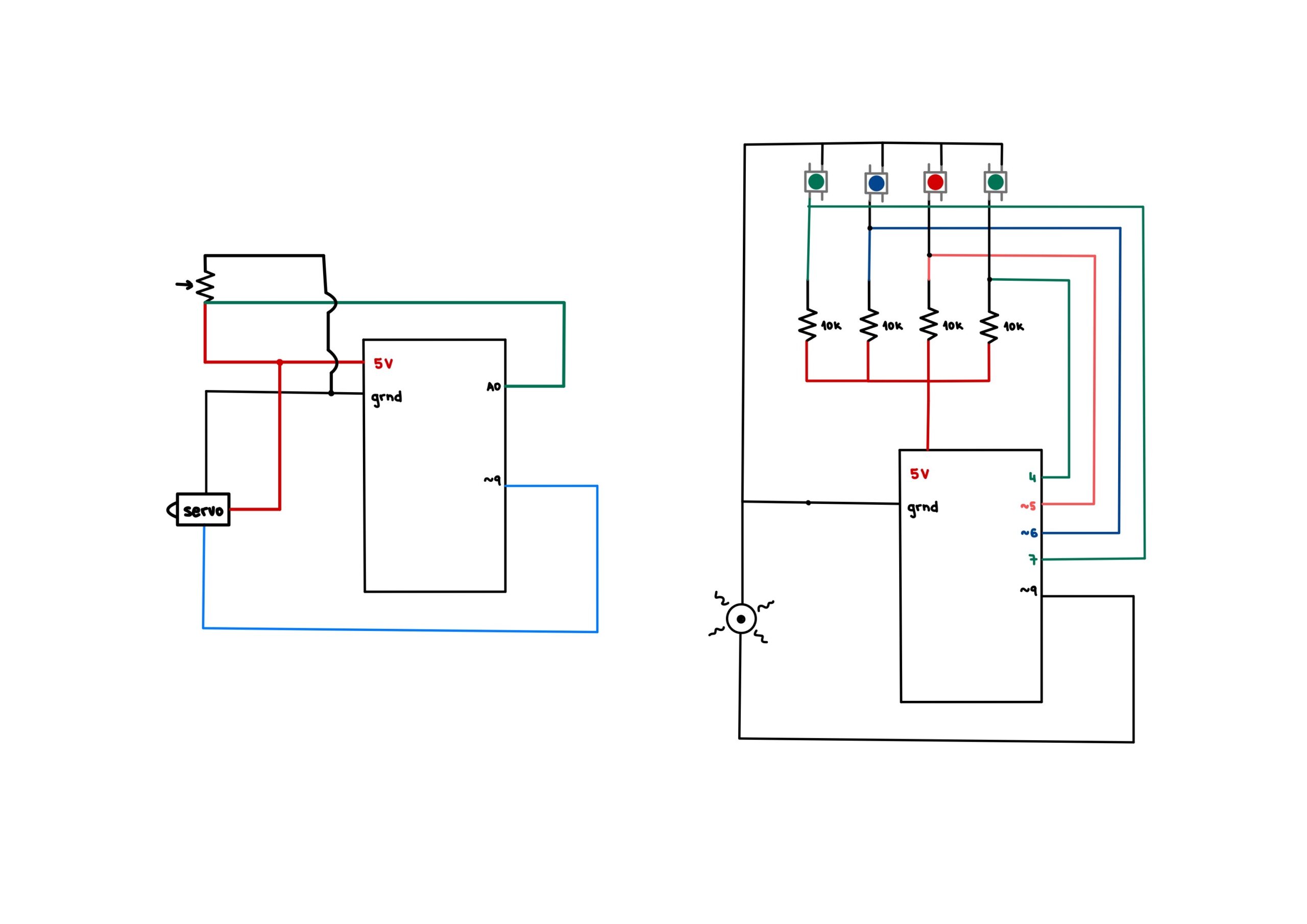
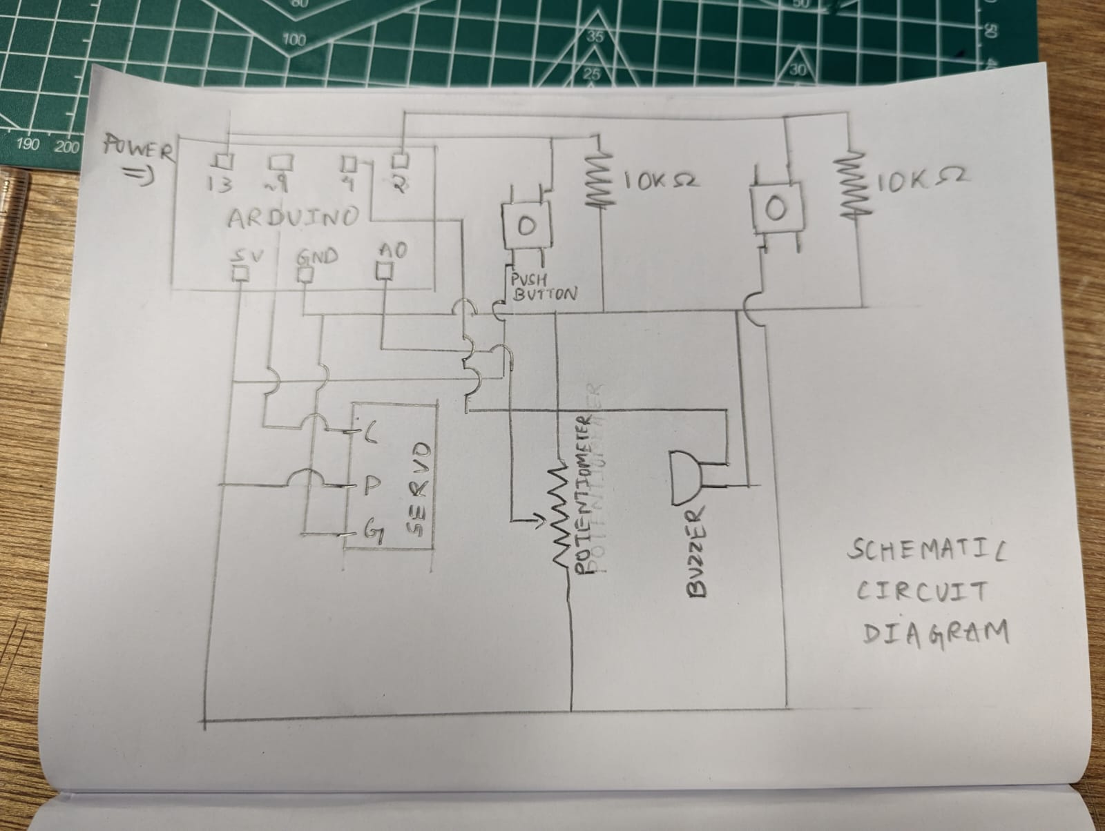
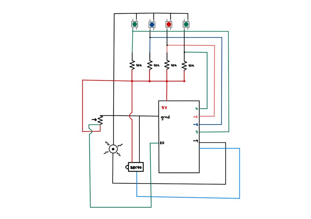
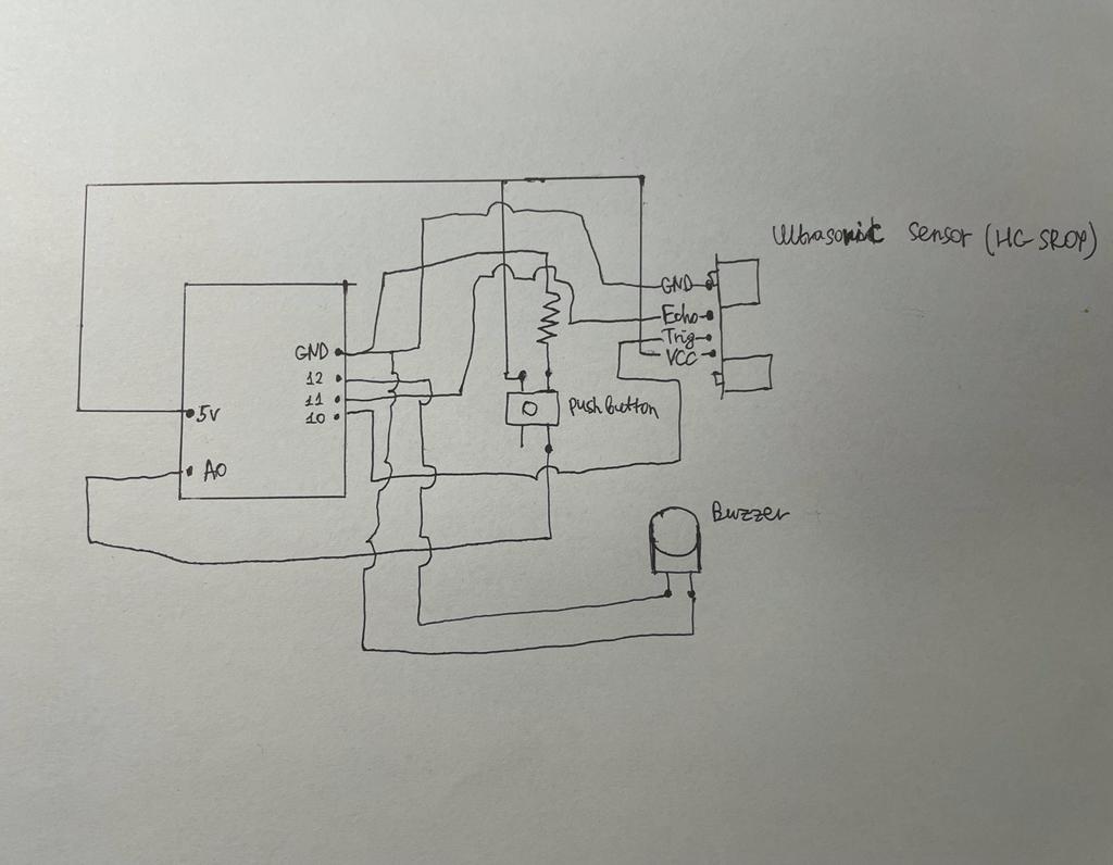
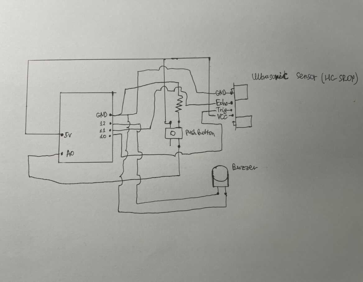
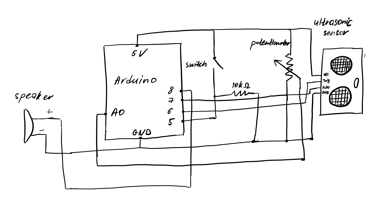
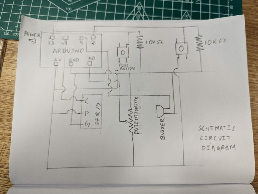
Schematic Diagram
Challenges
The main challenge that we have come across was making the location of the push buttons and the potentiometer user-friendly while taking wires into consideration. We had to play around with different versions of the breadboard construction multiple times to make sure the musical instrument was approachable and easy to use.
Moreover, we also considered multiple circuit designs for the buzzer in order to control the volume by adding resistors. Upon multiple trials, we have decided not to add a resistor for maximum volume and clarity.
For servo attachment, we looked around for a considerable time to find the most suitable extension to make the optimum beat sound. Before deciding on attaching the screwdriver to the rotational component of the servo, we considered using plastic and wooden extensions. For gaining the right sound of a beat, we realized we needed more weight for the attached piece, hence the final screwdriver extension was chosen. Putting a wooden plate below enhanced the experience, after our trial and error.
Another consideration was given to the response time of the servo, by adjusting the delay time in the moveServo() function. The final adjusted value of the delay was given according to what sounded natural according to the frequency at which the push button of the servo was pushed.
Reflections
Making this project together as a group was very enjoyable, which made the design process more exciting and fun. A part to improve on in the next projects would be in terms of having more power in choosing which tone to play on the buzzer rather than having to follow the set order that is programmed in the current version of the code. On a more general note, we would love to improve our ability to follow up what is happening in the circuit as it gets more complex, and making the schematic together definitely allowed us to work on that.

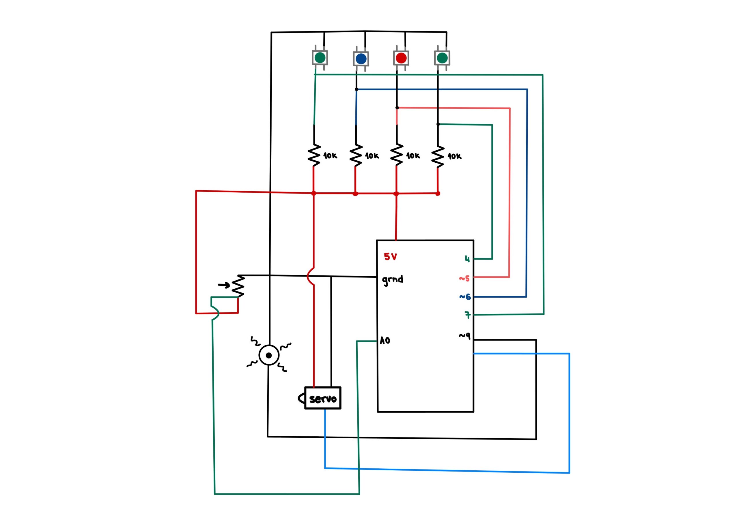
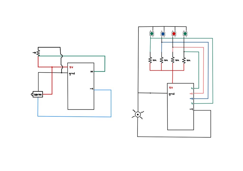
 The circuit
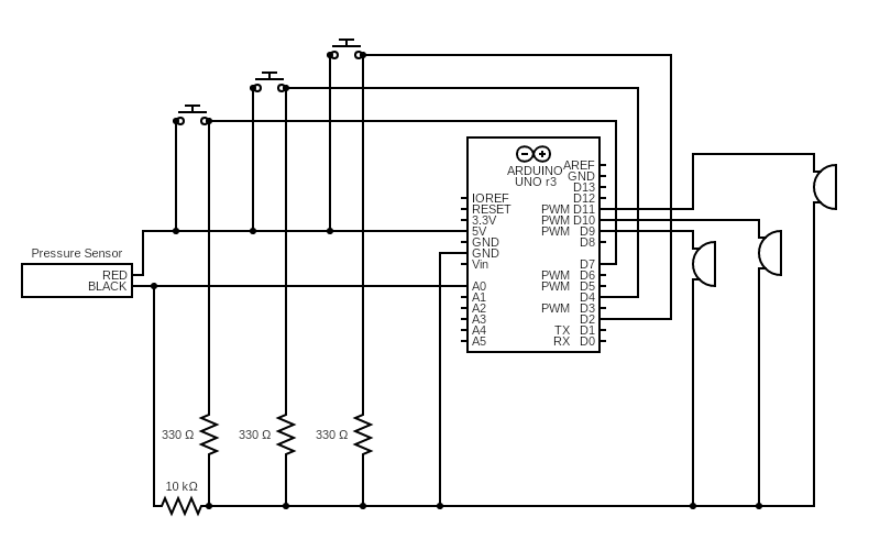 Circuit Diagram