For this assignment I had a very similar idea to Maimuna’s post about a car sensor which is usually what comes to mind when thinking of using an ultrasonic sensor. My project is also a car sensor, I just added more LED’s to fit my narrative of a warning meter which should go from “On” to red , to orange, then red proximity (in 2 intervals = 2 LED’s for each color).
I decided to use two LEDs for each level to indicate the different values that represent proximity which go from around 4- 4o, until the range is out of the ultrasonic sensor. Essentially, the last red LED will light up at around an output of 5, which means the car will hit the wall/object or is dangerously close to it.
I only used 1 white LED because it is only there to indicate that the car is within the range of the sensor to begin determining proximity.
One Issue that I had while working on this would be the LED’s. The first time I hooked everything up the LED’s were noticeably dim, this was not due to the resistors (I used 270 Ohms) but the LED’s themselves. I ended up switching out the LEDs I grabbed from the lab with the ones we had in the box which worked much more brighter as they have a voltage drop of 2.0-2.4v (unlike the ones in the lab, (I still don’t know their voltage drop).
For my demo, I just made a car from a food box and some tires I just taped to the sides.
Inspiration
Car sensors. Whenever an object or car comes very close to our car, it starts beeping and lighting. That was my motivation to create this sensor.
Video/Image
Work
Basically, as an object comes closer to the Ultrasonic sensor, the bulb lights. For the switch, I added a bulb connected switch- simply press the button.
Challenges
I had many issues with this assignment. It was mainly faulty jumper wires and Arduino’s functioning on Mac. At first, Changing jumper wires solved the issue of Ultrasonic sensor’s distance capture. I spent majority time on solving this 'avrdude: stk500_recv():' error. Re-installed the drivers, added new libraries, etc and magically it just started working!
for this week’s assignment, I struggled to come up with an idea for a few days, until I finally came up with the idea of creating some like this:
the idea was that it was instead a bathroom stall, and using an ultrasonic sensor, the light would either turn on or off, and I would use a side switch as a lock to determine if the light was red or green, occupied or empty. To learn how to use the ultrasonic sensor, I used the Sparkfun Arduino guidebook where they give many different examples and explanations on how to use different items in the kit, as well as a code to use the ultrasonic sensor. For the coding of the ultrasonic sensor, the most difficult part was getting the sensor to then return the distance it was measuring and use it in the code to determine the color of the light.
In trying to execute the idea, I thought that the switch would either turn on or off, so I couldn’t use it to change color, but instead, I could use the ultrasonic sensor to change the color. I then reconsidered and thought about using the ultrasonic sensor to determine the color of the lights to create a cross-walk where the distance of the pedestrian decided both the color of the light for them to cross and the color of the light for cars to pass by. To incorporate a button I wanted to make it so that if Dora reached the road but didn’t want to cross she could switch the color of the lights, make hers red and the light for the cars green, but I couldn’t get the code to work. I tried using two different if statements which I realized wouldn’t work and instead, I tried using && but what would happen is the lights would be off and turn on with the button, and once on when Dora was close, instead of having a green light and cars a red light they would both quickly flash red and green.
In the end, although it wasn’t what I wanted the button to be used for, I added it as headlights to the car, which wasn’t difficult besides having to be careful with the wires and making sure they were long enough.
In the future I think the more I understand how to code within Arduino, the more I will be able to accomplish.
I really wanted to make a cycling RGB light for this week’s homework so I did some research on the RGB LED in the kit and how to use it, and I ended up making a circuit in which the switch lets the user switch between control of the two LEDs, one RGB and the other just blue and a potentiometer to control the color of the RGB and the brightness of the other LED. To learn how to use the RGB LED, I went through other projects that used it online and learned that it sort of acts as 3 separate LEDs one red, one green and one blue. Using analogWrite() with each pin allows you to generate different colors the same way we used color() in p5js.
I wanted to make the light cycle through colors as seen in some gaming keyboards, for example. To achieve this, I mapped the value from the potentiometer to 0-767 (256×3), and I found that keeping one of the 3 colors at 0 and changing the other two colors according to the mapped value would achieve a nice cycling effect. I was inspired by this project to come up with this.
When the switch is pressed, the RGB LED would turn off, the blue LED would turn on and the potentiometer would then be used to control the brightness of the LED.
Here is my code and video:
bool pressed = false;
unsigned long timer = 0;
int prevButtonState = 0;
void setup() {
  Serial.begin(9600);
  pinMode(2, OUTPUT); //bluepin
  pinMode(3, OUTPUT); //redpin
  pinMode(5, OUTPUT); //greenpin
  pinMode(10, OUTPUT); //ledpin
  pinMode(9, OUTPUT); //switch
}
void loop() {
  int potValue = analogRead(A0);
  int buttonState  = digitalRead(9);
  if (buttonState == 1 && prevButtonState == 0){
    pressed = !pressed;
  }
  prevButtonState = buttonState;
  int mappedValue;
  int r;
  int g;
  int b;
  if (pressed){
    digitalWrite(2, LOW);
    mappedValue = map(potValue, 0, 1023, 0, 767);
    int color = mappedValue;
    color = constrain(color, 0, 767);
    if (color <= 255){
      r = 255 - color;
      g = color;
      b = 0;
    }
    else if (color <= 511){
      r = 0;
      g = 511 - color;
      b = color - 256;
    }
    else{
    r = color - 512;
    g = 0;
    b = 767 - color;
    }
    analogWrite(6, r);
    analogWrite(5, g);
    analogWrite(3, b);
  } else {
    analogWrite(6, 0);
    analogWrite(5, 0);
    analogWrite(3, 0);
    mappedValue = map(potValue, 0, 1023, 0, 255);
    analogWrite(10, mappedValue);
  }
}
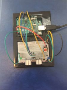
Thinking about the use of LEDs in a more practical and engineering way, I came up with the idea of creating an object detection sensor, which is widely used in tesla cars, home security systems, etc.
Implementation
As an object detector, I used an ultrasonic sensor (digital input). I also used a photosensor as a sort of solar power, which enables the work of the whole system (analog input).
There are three modes to detect an object depending on its distance from the ultrasonic sensor. You can identify if the object is close or far away by looking at which LED light is turned on and which sound is produced. If an object is close, the red LED will be turned on. If an object is at a medium distance, the yellow LED light turns on, which serves as a warning. And if an object is at a normal distance, the green LED is turned on all the time.
Code
int sensorPin = A0; // select the input pin for the potentiometer
int powerPin = 7;
int ledPin1 = 11; //  red LED
int ledPin2 = 10; // yellow LED
int ledPin3 = 9; // green LED
int buzzPin = 4;
const int trigPin = 12;
const int echoPin = 13;

long duration;
int distance;

bool gameStarted = false;

int sensorValue = 0; // variable to store the value coming from the sensor

void playSound(int hz) {
  tone(buzzPin, hz);
  delay(hz);
  noTone(buzzPin);
}

void setup() {
  // declare the ledPins as an OUTPUT:
  pinMode(ledPin1, OUTPUT);
  pinMode(ledPin2, OUTPUT);
  pinMode(ledPin3, OUTPUT);
  pinMode(buzzPin, OUTPUT);
  pinMode(sensorPin, INPUT);
  pinMode(powerPin, OUTPUT);
  pinMode(trigPin, OUTPUT);
  pinMode(echoPin, INPUT);

  Serial.begin(9600);
}

void loop() {
  digitalWrite(trigPin, LOW);
  delayMicroseconds(2);
  digitalWrite(trigPin, HIGH);
  delayMicroseconds(10);
  digitalWrite(trigPin, LOW);

  duration = pulseIn(echoPin, HIGH);
  distance = duration * 0.034 / 2;

  digitalWrite(powerPin, HIGH);

  sensorValue = analogRead(sensorPin);
  Serial.println(sensorValue);

  //to turn on the object detection by photo sensor (solar power)
  if (sensorValue <= 30) {
    gameStarted = false;
    delay(2000);
  }

  //if there is no light, the system does not work
  else if (sensorValue > 30) {
    gameStarted = true;
  }

  if (gameStarted) { //to measure a distance
    if (distance <= 5) { //red led turns on at the lowest distance

      // turn the ledPin on
      digitalWrite(ledPin1, HIGH);
      digitalWrite(ledPin2, LOW);
      digitalWrite(ledPin3, LOW);
      playSound(200);

      delay(100);
      // turn the ledPin off:
      digitalWrite(ledPin1, LOW);
      digitalWrite(ledPin2, LOW);
      digitalWrite(ledPin3, LOW);
      delay(100);
    }
    else if (distance > 5 && distance <= 10) { //yellow led turns on at the medium distance
      digitalWrite(ledPin1, LOW);
      digitalWrite(ledPin2, HIGH);
      digitalWrite(ledPin3, LOW);
      playSound(1000);

      delay(100);
      digitalWrite(ledPin1, LOW);
      digitalWrite(ledPin2, LOW);
      digitalWrite(ledPin3, LOW);
      delay(100);
    }

    else if (distance > 10) { //to turn on the green led

      digitalWrite(ledPin1, LOW);
      digitalWrite(ledPin2, LOW);
      digitalWrite(ledPin3, HIGH);

      delay(100);

      digitalWrite(ledPin1, LOW);
      digitalWrite(ledPin2, LOW);
      digitalWrite(ledPin3, LOW);

      delay(100);
    }
  }
}
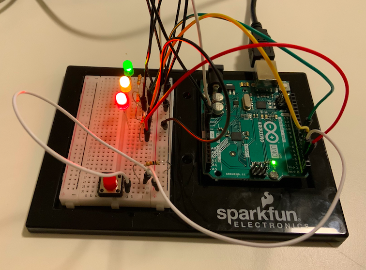
When faced with the use of both analog and digital sensors, my mind initially went to cars. Especially their interface right in front of the steering wheel that indicates fuel, if lights are turned on or off, speed, and many other components. I imagine they must use both, digital and analog circuits, for all these LED’s and indicators. And thus, decided to build my own. Throughout my brainstorm process I was also reminded of Ruta, my favorite card game. In this board game, you need a green light card to signify the car running. A yellow/red light would indicate you could not drive, nor obtain points.
Building Process 🚧:
Going off from this concept, I placed three LED’s, a red one, a yellow one, and a green one in the shape of a stoplight. This would be my visualization of the car running or not. I then added three elements that are crucial for driving successfully:
Pressing the Accelerator
Adjusting the Steering Wheel
Turning on the Headlights if it’s dark
With these requirements, I built the following:
A digital circuit for the red light. It is on, only if you press on the red button, which represents the gas pedal.
A circuit with an analog sensor for the yellow LED. It will blink unless the steering wheel, a potentiometer, is oriented towards the right side, in which it will be turned off.
An analog circuit with the Blue LED light. It will light up as per the light it receives from the photosensor.
IF the light received passes a certain threshold, the accelerator is pressed, and the steering wheel is facing the correct way, the green light will turn on, and you will be on your way!
Here is my Code:
const int greenPin = 7;
const int yellowPin = 4;
const int redPin = 2;
const int buttonPin = 3;
const int wheelPin = 8;
const int bluePin = 9;
unsigned long timer = 0;
bool onOff = LOW;

void setup() {
  Serial.begin(9600);
 pinMode(greenPin, OUTPUT);
 pinMode(yellowPin, OUTPUT);
 pinMode(redPin, OUTPUT);
 pinMode(bluePin, OUTPUT);
 pinMode(buttonPin, INPUT);

}

void loop() {
bool redState = digitalRead(redPin);
bool yellowState = digitalRead(yellowPin);

// RED //
byte buttonState = digitalRead(buttonPin);

if (buttonState == HIGH) {
  digitalWrite(redPin, LOW);
} else
{digitalWrite(redPin, HIGH);}
// RED//

//YELLOW//
int wheelValue = analogRead(A0);
int mappedValue = map(wheelValue, 0, 1023, 0, 255);


if (mappedValue > 110 && mappedValue < 140) {
  digitalWrite(yellowPin, LOW);
} else {

 if(millis()>timer){
      onOff = !onOff;
      timer = millis() + 200;
      digitalWrite(yellowPin, onOff);
      }
      }

//YELLOW//


// BLUE //
int lightValue = analogRead(A1);
int mappedLightValue = map(lightValue, 655, 1000, 0, 255);
int constrainedValue = constrain(mappedLightValue, 0, 255);

analogWrite(bluePin, constrainedValue);
//Serial.println(lightValue);
// BLUE //

// GREEN //
if (redState == LOW && yellowState == LOW && mappedValue > 110 && mappedValue < 140 && constrainedValue > 200){

 digitalWrite(greenPin, HIGH);
} else {
  digitalWrite(greenPin, LOW);
  }
// GREEN //

}
Initially, I had the yellow LED to blink at a speed determined by the analog input of the potentiometer. The higher the value, the fastest the blinking. However, this gave the project an unorganized structure and distracted the user from the goal of turning on the car. Thus, I gave it a set value.
Another important thing to note is that during the day, the blue LED will always be turned on. This is intentional, and is used to signify how headlights are only needed at night. If you wish to change this, alter the mappedLightValue variable and make the 655 higher to a threshold of about 950+.
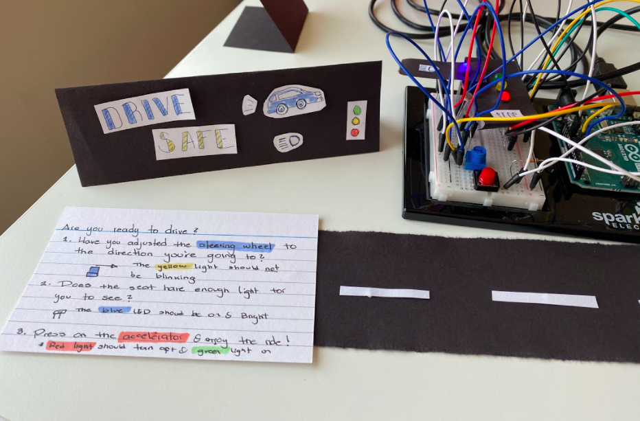
Final Product 🚨:
I am very happy with how Drive Safe turned out. After I completed the circuit, I made some decorations to make it look cleaner and easier to understand. I have tested it multiple times, in multiple scenarios and it seems to work perfectly fine. I also wrote a set of instructions for anyone using it without me.
In the future, I would like to experiment with other type of sensors, and figure out a way to make cables not visible, as they damage the aesthetic quality of the piece a lot.
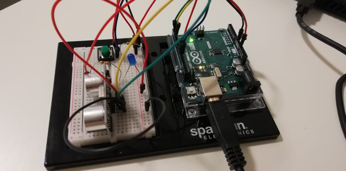
In this assignment, I decided to make study lamp which can be turned on or off and have adjustable brightness. To implement this, I decided to make an LED respond to how close I am to it. The LED is turned on using the switch and its brightness is varied using the ultrasonic sensor. I calculate the distance away from the ultrasonic sensor in centimeters using the time it takes for the ultrasonic sensor to read the trigger pulses. Now, the closer I am to the ultrasonic sensor, the brighter the LED becomes if it is switched on. So, when I am studying, I can change the brightness levels depending on how close I sit next to the ultrasonic sensor.
Here is the circuit:
Here is the code:
const int trigPin = 3;
const int echoPin = 2;
const int led = 9;
const int buttonInp = 11;

bool run = false;
bool prevButtonState = LOW;

long duration;
int distance;

void setup() {
  pinMode(trigPin, OUTPUT);
  pinMode(echoPin, INPUT);
  pinMode(led, OUTPUT);
  pinMode(buttonInp, INPUT);
  Serial.begin(9600);
}
void loop() {
  byte buttonState  = digitalRead(buttonInp);

  Serial.println(buttonState);

  // check to see if the button is pressed and last time it wasn't
  if (buttonState == HIGH && prevButtonState == LOW) {
    //toggle run
    run = !run;
  }
  // record the current button state for use next time through loop
  prevButtonState = buttonState;

  if(run){
    // Clear trigPin
    digitalWrite(trigPin, LOW);
    delayMicroseconds(2);

    //Set trigPin to HIGH state for 10 micro seconds
    digitalWrite(trigPin, HIGH);
    delayMicroseconds(10);
    digitalWrite(trigPin, LOW);

    // Reads the echoPin, returns the sound wave travel time in microseconds
    duration = pulseIn(echoPin, HIGH);

    // Calculating the distance
    distance = duration * 0.034 / 2;
    // Serial.println(distance);

    // Adjusting brightness of LED to be distance mapped to 0-255
    int brightness = map(distance, 0, 15, 0, 255);
    brightness = constrain(brightness, 0, 255);
    brightness = 255 - brightness;
    analogWrite(led, brightness);
  }
  else {
    //LED off
    digitalWrite(led, LOW);
  }
}
My idea was to make a traffic light with the red, yellow and green LEDs. I decided to use a single switch button that cycles between modes as well as a potentiometer that changes the LED activated.
In order to make the button that cycles between modes, I got a lot of help from https://gist.github.com/navillus5/6699360
The 3 modes of my traffic light:
All LEDS blinking
Potentiometer activates either of the red, yellow, and green LEDs when dialed to a specific point
Off
Overall I think I executed my idea well as everything I intended for the assignment works, however one small issue I ran into is that when switched to the 2nd mode, the LEDS are very dim. My best guess is that it has to do with the resistors but I haven’t tested out this theory as I don’t want to accidentally damage my LEDs.
My Code:
const int buttonPin = 3;
const int redLight = 9;
const int yellowLight = 6;
const int greenLight = 5;
unsigned long timer = 0;
bool onOff = LOW;
byte prevButtonState = LOW;
bool blinking = false;
byte buttonMode = 0;
bool traffic = false;

boolean currentState = LOW;
boolean lastState    = LOW;
boolean stateChange  = false;

int currentButton = 0;
int lastButton    = 2;

void setup() {
  // put your setup code here, to run once:
  Serial.begin(9600);
  pinMode(redLight, OUTPUT);
  pinMode(yellowLight, OUTPUT);
  pinMode(greenLight, OUTPUT);
  digitalWrite(redLight, LOW);
  digitalWrite(yellowLight, LOW);
  digitalWrite(greenLight, LOW);
  pinMode(buttonPin, INPUT);
}

void loop() {
  currentState = debounceButton();
  stateChange = checkForChange(currentState, lastState);
  currentButton = getButtonNumber(lastButton, currentState, stateChange);
  lastState  = currentState;
  lastButton = currentButton;

  // put your main code here, to run repeatedly:
  int potValue = analogRead(A0);
  int mappedPotValue = map(potValue, 0, 1023, 0, 255);
  int constrainedPotValue = constrain(mappedPotValue, 0, 255);
  Serial.println(currentButton);
//  byte buttonState  = digitalRead(buttonPin);

  if (currentButton == 0) {
    blinking = true;
//    buttonMode = buttonMode + 1;
  }
  if (currentButton == 1) {
    blinking = false;
    traffic = true;
  }
  if (currentButton == 2) {
    traffic = false;
  }

  if (traffic == true) {
    if (constrainedPotValue > 170) {
       digitalWrite(redLight, HIGH);
       digitalWrite(yellowLight, LOW);
       digitalWrite(greenLight, LOW);
    }
    if (constrainedPotValue <= 170 && constrainedPotValue > 85) {
       digitalWrite(redLight, LOW);
       digitalWrite(yellowLight, HIGH);
       digitalWrite(greenLight, LOW);
    }
    if (constrainedPotValue <= 85) {
      digitalWrite(redLight, LOW);
      digitalWrite(yellowLight, LOW);
      digitalWrite(greenLight, HIGH);
    }
  }

  if (blinking == true) {
    if (millis() > timer) {
      onOff = !onOff;
      timer = millis() + 250;
      digitalWrite(redLight, onOff);
      digitalWrite(yellowLight, onOff);
      digitalWrite(greenLight, onOff);
    }
  } else {
    digitalWrite(redLight, LOW);
    digitalWrite(yellowLight, LOW);
    digitalWrite(greenLight, LOW);
  }
}

// FUNCTIONS

//debounce
boolean debounceButton()
{
  boolean firstCheck   = LOW;
  boolean secondCheck  = LOW;
  boolean current = LOW;
  firstCheck  = digitalRead(buttonPin);
  delay(50);
  secondCheck = digitalRead(buttonPin);
  if (firstCheck == secondCheck){
    current = firstCheck;
  }
  return current;
}


//checks for change
boolean checkForChange(boolean current, boolean last)
{
  boolean change;
  if (current != last){
    change = true;
  }
  else {
  change = false;
  }
  return change;
}

//gets button num
int getButtonNumber(int button, boolean state, boolean change)
{
  if (change == true && state == LOW){
    button++;
    if (button > 2){
      button = 0;
    }
    Serial.println(button);
  }
  return button;
}
My idea for the assignment is a person who is studying, turned on his desk lamp (digital input and output) then doses off and as the pressure sensor senses the body, the light starts dimming (analog input and output).
const int ledPin = 2;
const int buttonPin = 3;
const int eyePin = 5;
int pressureValue = A0;

byte prevButtonState = LOW;
bool brightness = HIGH;

void setup() {
  // put your setup code here, to run once:
  pinMode(ledPin, OUTPUT);
  pinMode(buttonPin, INPUT);
  pinMode(eyePin, OUTPUT);
  pinMode(pressureValue, INPUT);

  Serial.begin(9600);
}

void loop() {
  // read the button pin
  // store that in a local variable
  byte buttonState  = digitalRead(buttonPin);
  int pressureValue = analogRead(A0);

 int mappedPressureValue = map(pressureValue, 0,400, 0, 255);
  Serial.print(pressureValue);

   int constrainedValue = constrain(mappedPressureValue, 0, 255);
    analogWrite(5, constrainedValue);//0-255

  // print out the state of the button stored in the variable
  // record the current button state for use next time through loop
  prevButtonState = buttonState;


  if (buttonState == HIGH && prevButtonState == LOW) {
   digitalWrite(ledPin, HIGH);
    }
  // otherwise turn the LED off
   else {
    digitalWrite(ledPin, LOW);
  }
}
The inspiration for the project is Christmas tree decorations that have LED light bulbs blinking to make the tree look pretty.
There are one analog and one digital input that the circuit includes.
Digital – The red digital button switch chooses the blinking mode of the LED lights. (1 – off, 2 – on, 3 – blinks)
Analog – The potentiometer’s input decides the speed of the blinking of the LED lights and also the speed of the carol being played from the speaker.
How I implemented the Carol to be played in the speaker – First, I made an array of melodies where “0” indicates MUTE and from 1 to 11 each means a note. As time passes, the index will move on to the next element in the melodies array, playing the music as it is written in the melodies array.
The code I used is inserted below.
I have bad connections with the blue lightbulbs, so it sometimes turns off in the video.
I was going to make mode #4 that automatically turns the light bulb on and off depending on the light in the room, but I think I broke my light sensor while bending it, and was not able to make it happen.