How to embed a p5js sketch in your blog post

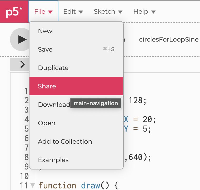
In the p5js editor under File click Share:
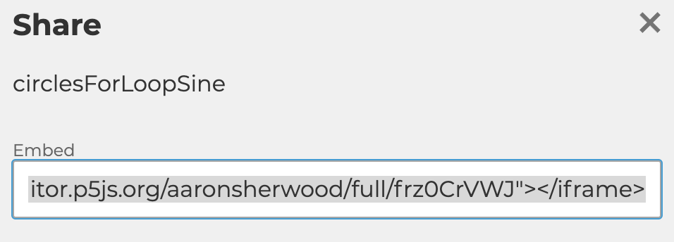
Copy the code it has there under Embed:
In the upper left hand corner of the WordPress editor click Text:

Paste the embed code there in the spot where you’d like your sketch to be placed in your post. Add the width and height of your sketch to your iframe element and add about 44 pixels to account for the p5 logo above the embedded sketch. For example, if your sketch is 640×640 pixels add width=640 height=684. If your sketch uses the camera or microphone you can give permission to use these in the embedded sketch by adding allow=”camera;microphone”.

Example:

<iframe src="https://editor.p5js.org/aaronsherwood/full/frz0CrVWJ" width=640 height=684 allow="camera;microphone"></iframe>


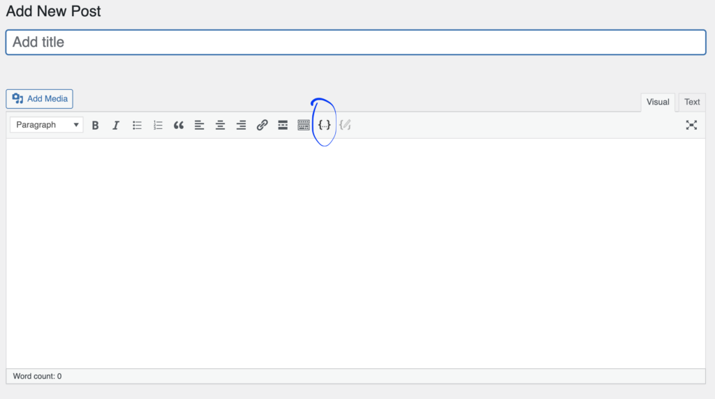
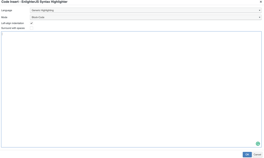
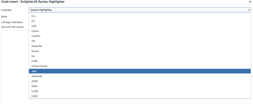
To include a code snippet you can use the Enlighter syntax highlighter. In the WordPress editor click the {..} code insertion icon.

Paste your code snippet and select JavaScript as the code language.
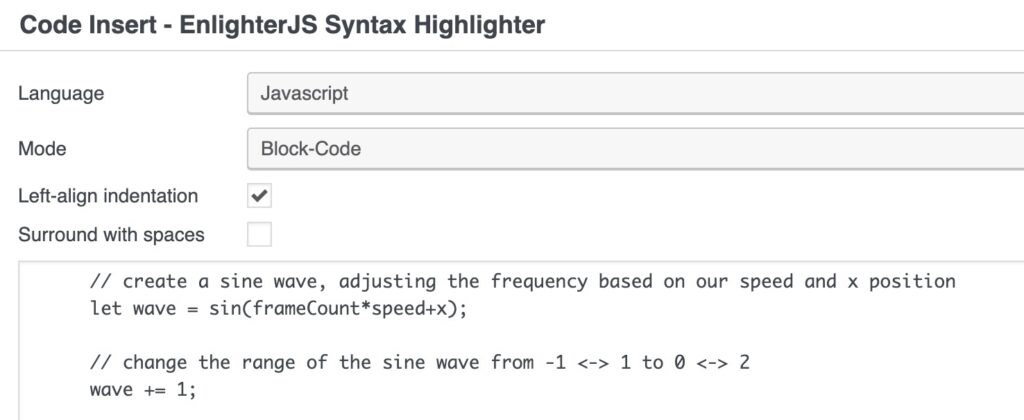
The result should look like this:

// create a sine wave, adjusting the frequency based on our speed and x position
let wave = sin(frameCount*speed+x);

// change the range of the sine wave from -1 <-> 1 to 0 <-> 2
wave += 1;


Serial Communication

int left = 0;
int right = 0;

void setup() {
  Serial.begin(9600);
  Serial.println("0,0");
  pinMode(2, OUTPUT);
  pinMode(5, OUTPUT);
}

void loop() {
  while (Serial.available()) {
    right = Serial.parseInt();
    left = Serial.parseInt();
    if (Serial.read() == '\n') {
      digitalWrite(2, right);
      digitalWrite(5, left);
      int sensor = analogRead(A0);
      delay(1);
      int sensor2 = analogRead(A1);
      delay(1);
      Serial.print(sensor);
      Serial.print(',');
      Serial.println(sensor2);
    }
  }
}

/*

import processing.serial.*;
Serial myPort;
int xPos=0;
int yPos=0;
boolean onOff=false;
boolean onOff2=false;

void setup(){
  size(960,720);
  printArray(Serial.list());
  String portname=Serial.list()[1];
  println(portname);
  myPort = new Serial(this,portname,9600);
  myPort.clear();
  myPort.bufferUntil('\n');
}

void draw(){
  background(255);
  ellipse(xPos,yPos,30,30);
  if (mousePressed){
    if(mouseX<=width/2)
      onOff2=true;
    else
      onOff=true;
  }else{
    onOff=onOff2=false;
  }
}

void serialEvent(Serial myPort){
  String s=myPort.readStringUntil('\n');
  s=trim(s);
  if (s!=null){
    println(s);
    int values[]=int(split(s,','));
    if (values.length==2){
      xPos=(int)map(values[0],0,1023,0, width);
      yPos=(int)map(values[1],0,1023,0, height);
    }
  }
  myPort.write(int(onOff)+","+int(onOff2)+"\n");
}

 */

All serial examples: https://github.com/aaronsherwood/introduction_interactive_media/tree/master/arduinoExamples/serialExamples

  1. make something that uses only one sensor  on arduino and makes the ellipse in processing move on the horizontal axis, in the middle of the screen, and nothing on arduino is controlled by processing
  2. make something that controls the LED brightness from processing
  3. take the gravity wind example below and make it so every time the ball bounces one led lights up and then turns off, and you can control the wind from one analog sensor
PVector velocity;
PVector gravity;
PVector position;
PVector acceleration;
PVector wind;
float drag = 0.99;
float mass = 50;
float hDampening;

void setup() {
  size(640,360);
  noFill();
  position = new PVector(width/2, 0);
  velocity = new PVector(0,0);
  acceleration = new PVector(0,0);
  gravity = new PVector(0, 0.5*mass);
  wind = new PVector(0,0);
  hDampening=map(mass,15,80,.98,.96);
}

void draw() {
  background(255);
  if (!keyPressed){
    wind.x=0;
    velocity.x*=hDampening;
  }
  applyForce(wind);
  applyForce(gravity);
  velocity.add(acceleration);
  velocity.mult(drag);
  position.add(velocity);
  acceleration.mult(0);
  ellipse(position.x,position.y,mass,mass);
  if (position.y > height-mass/2) {
      velocity.y *= -0.9;  // A little dampening when hitting the bottom
      position.y = height-mass/2;
    }
}
  
void applyForce(PVector force){
  // Newton's 2nd law: F = M * A
  // or A = F / M
  PVector f = PVector.div(force, mass);
  acceleration.add(f);
}

void keyPressed(){
  if (keyCode==LEFT){
    wind.x=-1;
  }
  if (keyCode==RIGHT){
    wind.x=1;
  }
  if (key==' '){
    mass=random(15,80);
    position.y=-mass;
    velocity.mult(0);
  }
}


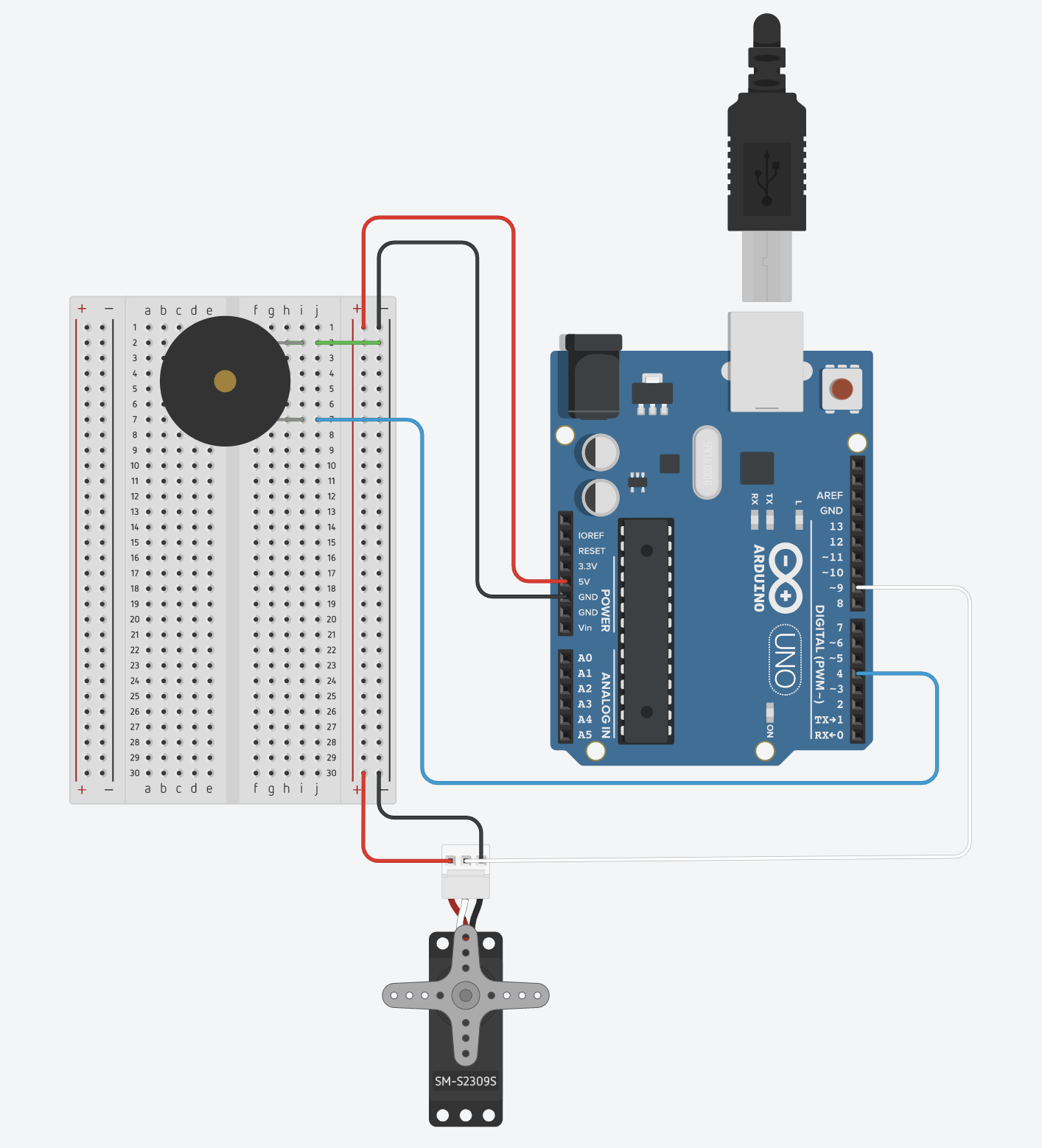
Servo and Tone

pitches.h:

/*************************************************

 * Public Constants

 *************************************************/

#define NOTE_B0  31
#define NOTE_C1  33
#define NOTE_CS1 35
#define NOTE_D1  37
#define NOTE_DS1 39
#define NOTE_E1  41
#define NOTE_F1  44
#define NOTE_FS1 46
#define NOTE_G1  49
#define NOTE_GS1 52
#define NOTE_A1  55
#define NOTE_AS1 58
#define NOTE_B1  62
#define NOTE_C2  65
#define NOTE_CS2 69
#define NOTE_D2  73
#define NOTE_DS2 78
#define NOTE_E2  82
#define NOTE_F2  87
#define NOTE_FS2 93
#define NOTE_G2  98
#define NOTE_GS2 104
#define NOTE_A2  110
#define NOTE_AS2 117
#define NOTE_B2  123
#define NOTE_C3  131
#define NOTE_CS3 139
#define NOTE_D3  147
#define NOTE_DS3 156
#define NOTE_E3  165
#define NOTE_F3  175
#define NOTE_FS3 185
#define NOTE_G3  196
#define NOTE_GS3 208
#define NOTE_A3  220
#define NOTE_AS3 233
#define NOTE_B3  247
#define NOTE_C4  262
#define NOTE_CS4 277
#define NOTE_D4  294
#define NOTE_DS4 311
#define NOTE_E4  330
#define NOTE_F4  349
#define NOTE_FS4 370
#define NOTE_G4  392
#define NOTE_GS4 415
#define NOTE_A4  440
#define NOTE_AS4 466
#define NOTE_B4  494
#define NOTE_C5  523
#define NOTE_CS5 554
#define NOTE_D5  587
#define NOTE_DS5 622
#define NOTE_E5  659
#define NOTE_F5  698
#define NOTE_FS5 740
#define NOTE_G5  784
#define NOTE_GS5 831
#define NOTE_A5  880
#define NOTE_AS5 932
#define NOTE_B5  988
#define NOTE_C6  1047
#define NOTE_CS6 1109
#define NOTE_D6  1175
#define NOTE_DS6 1245
#define NOTE_E6  1319
#define NOTE_F6  1397
#define NOTE_FS6 1480
#define NOTE_G6  1568
#define NOTE_GS6 1661
#define NOTE_A6  1760
#define NOTE_AS6 1865
#define NOTE_B6  1976
#define NOTE_C7  2093
#define NOTE_CS7 2217
#define NOTE_D7  2349
#define NOTE_DS7 2489
#define NOTE_E7  2637
#define NOTE_F7  2794
#define NOTE_FS7 2960
#define NOTE_G7  3136
#define NOTE_GS7 3322
#define NOTE_A7  3520
#define NOTE_AS7 3729
#define NOTE_B7  3951
#define NOTE_C8  4186
#define NOTE_CS8 4435
#define NOTE_D8  4699
#define NOTE_DS8 4978
#include <Servo.h>
#include "pitches.h"

Servo servo;
int servoPos = 100;
int whichNote = 0;
int notes[10] = {NOTE_C4, NOTE_D4, NOTE_E4, NOTE_F4, NOTE_G4, NOTE_A4, NOTE_B4, NOTE_C5, NOTE_D5, NOTE_E5};
int durations[10];

void setup() {
  servo.attach(9);
  pinMode(3, OUTPUT);
  Serial.begin(9600);

  // set the durations with a random coinflip
  for (int i = 0; i < 10; i++) {
    int coinFlip = random(2);
    if (coinFlip == 0)
      durations[i] = 8;
    else
      durations[i] = 4;
  }
}

void loop() {
  int val = analogRead(A0);

  // the rate is 1 second divided by the duration of the note
  int rate = 1000 / durations[whichNote];
 
  // get the current time
  unsigned long currentTime = millis();

  // trigger a note
  if (currentTime % rate == 0  ) {
    tone(4, notes[whichNote], random(100, 400));
    whichNote = random(10);
    delay(1);
  }

  // do the servo at half speed
  if (currentTime % (rate * 2) == 0  ) {
    servoPos = 50;
    servo.write(servoPos);
  } 
  
  // else if not triggereing the servo, then every 10 milliseconds move the servo arm back a little bit
  // can't do it every frame as that is too fast for the servo
  else if (currentTime % 10 == 0) {
    servoPos -= 1;
    servo.write(servoPos);
  }
}
  • Timer0 – used for millis(), micros(), delay() and PWM on pins 5 & 6
  • Timer1 – used for Servos, the WaveHC library and PWM on pins 9 & 10
  • Timer2 – used by Tone and PWM on pins 3 & 11

Analog Input & Output

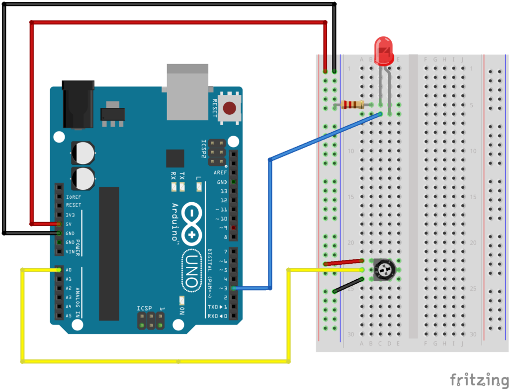
Potentiometer:

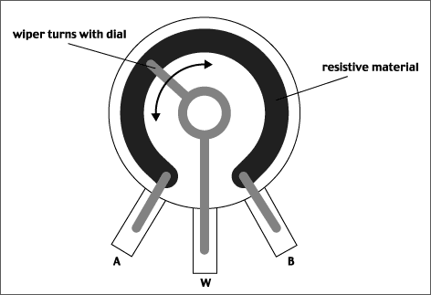
Inside a potentiometer:
potentiometer1.gif (472×323)

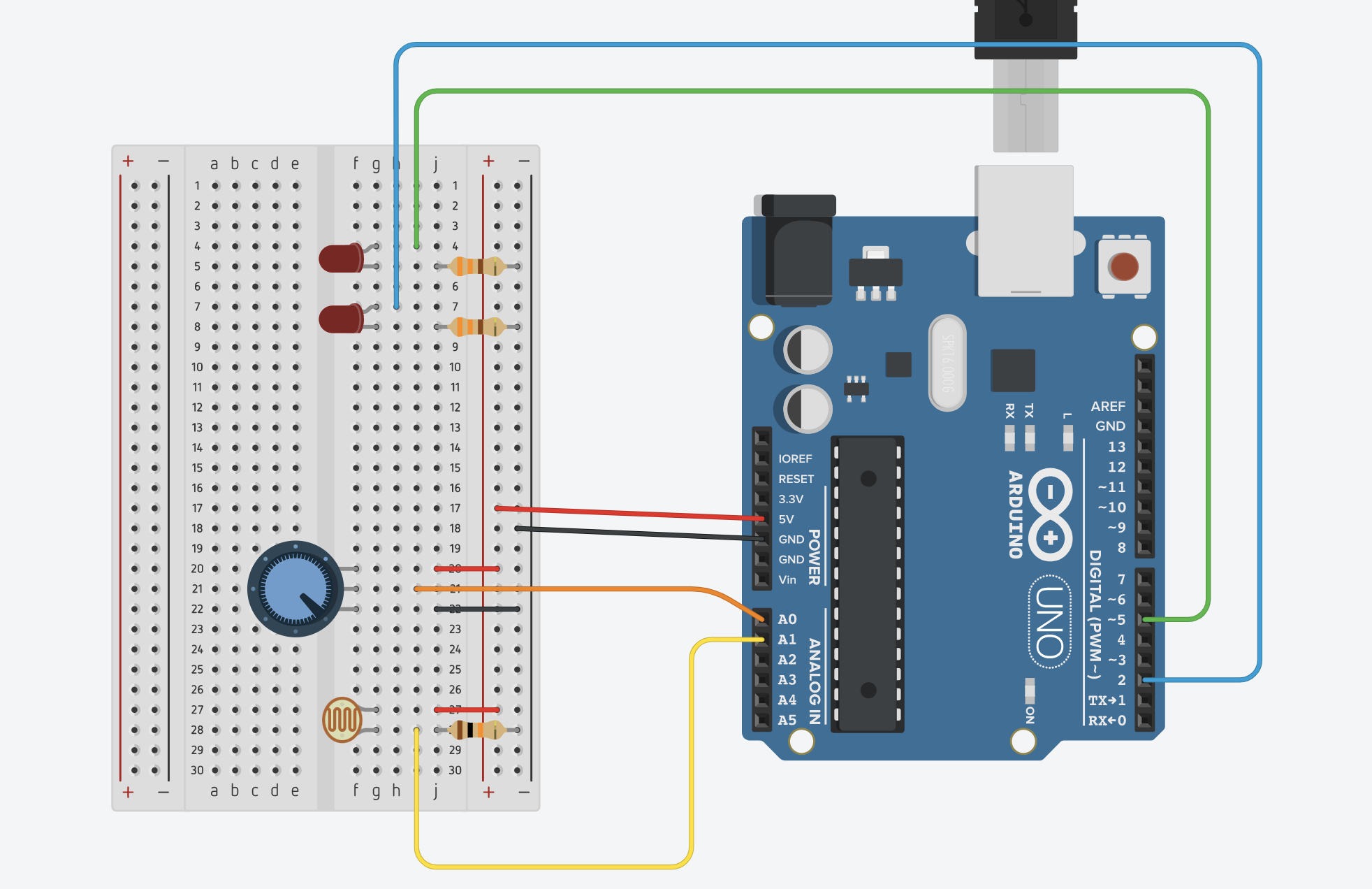
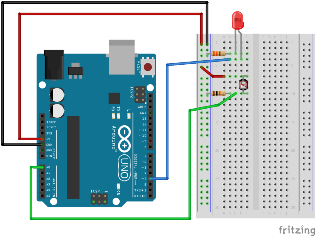
Photoresistor:

Pulse Width Modulation:
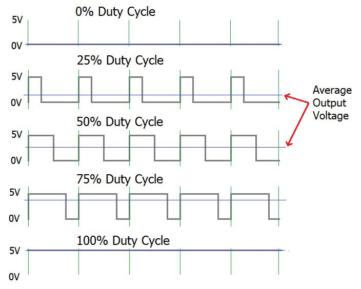
What is PWM: Pulse Width Modulation

const int ledPin = 2;
bool ledState = LOW;

// a really longer number with no + or - sign
unsigned long toggleTime = 0;
int triggerInterval = 500;

void setup() {
  pinMode(ledPin, OUTPUT);
  Serial.begin(9600);
}

void loop() {
  // read the analog input
  int knobValue = analogRead(A0);
  // map that input to a range appropriate for our use
  // in this case, we take the range of the photocell and map it to millis between 10 & 500
  // this is the blink interval for the LED
  triggerInterval = map(knobValue, 190, 860, 10, 500);

  // print out the original value and the mapped value on the same line
  Serial.print(knobValue);
  Serial.print(" ");
  Serial.println(triggerInterval);

  // if the current time (millis) is more than the exact time when we are supposed to toggle
  if (millis() > toggleTime) {
    // flip the LED to the opposite of what it was
    ledState = !ledState;
    // set the next time the LED should toggle
    // to the current time + whatever the blink interval amount of time is
    toggleTime = millis() + triggerInterval;
  }

  // turn the LED on or off based on the ledState vaviable
  digitalWrite(ledPin, ledState);
}


Arduino First Steps!

Electricity slides from class

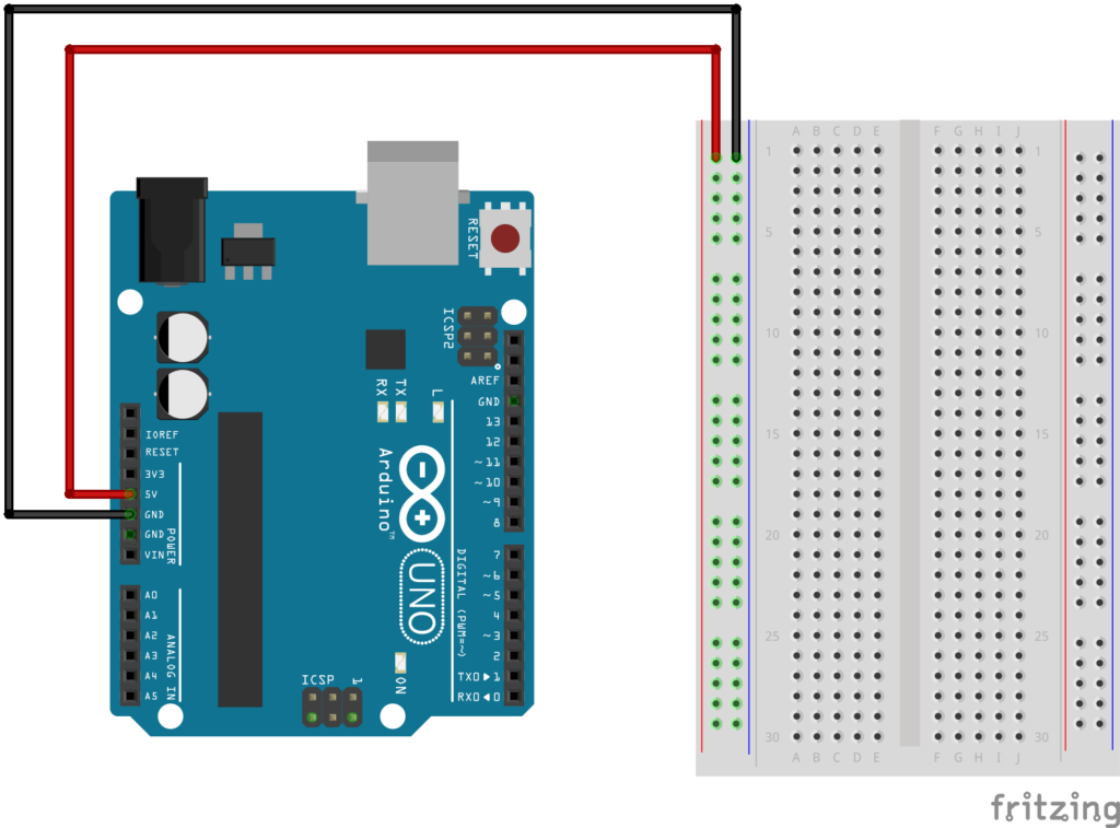
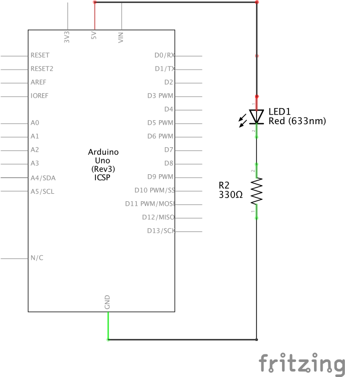
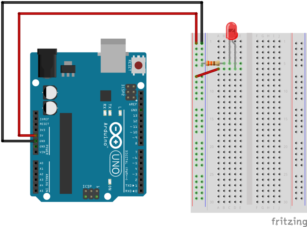
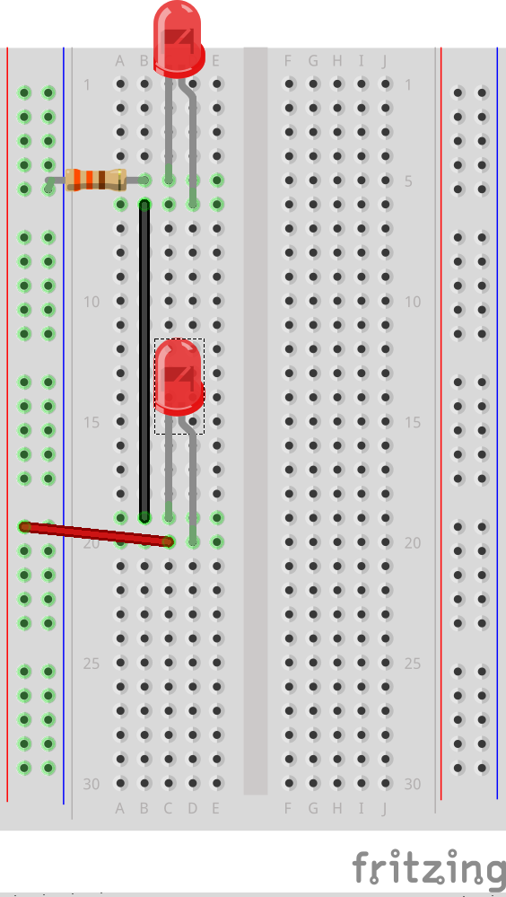
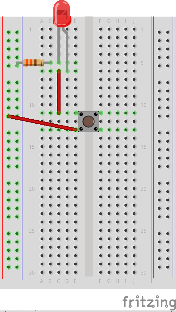
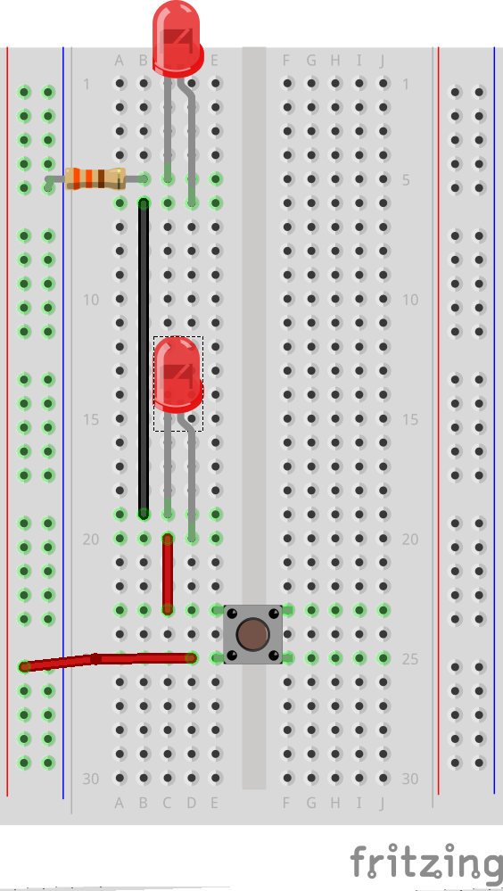
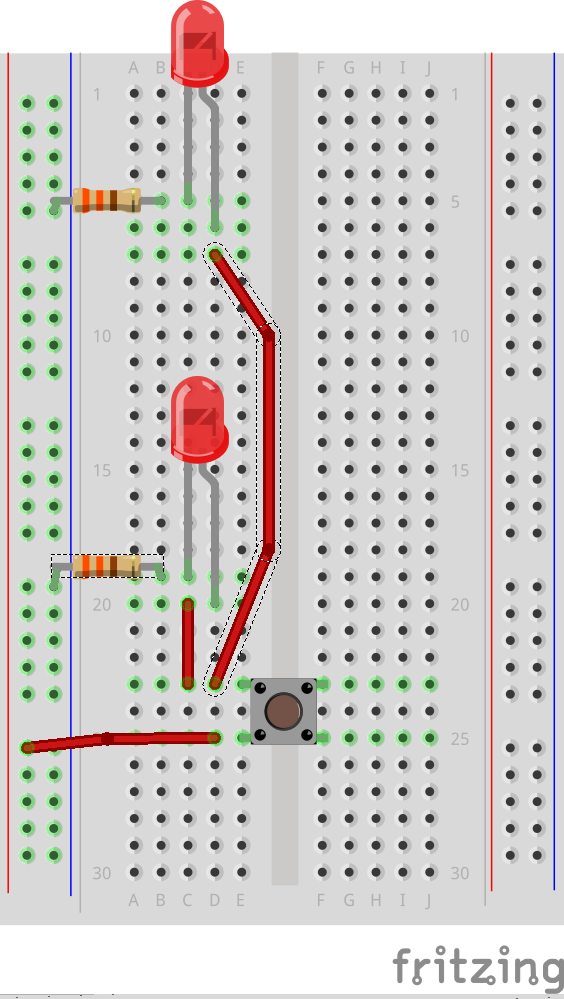
Basic Circuits:

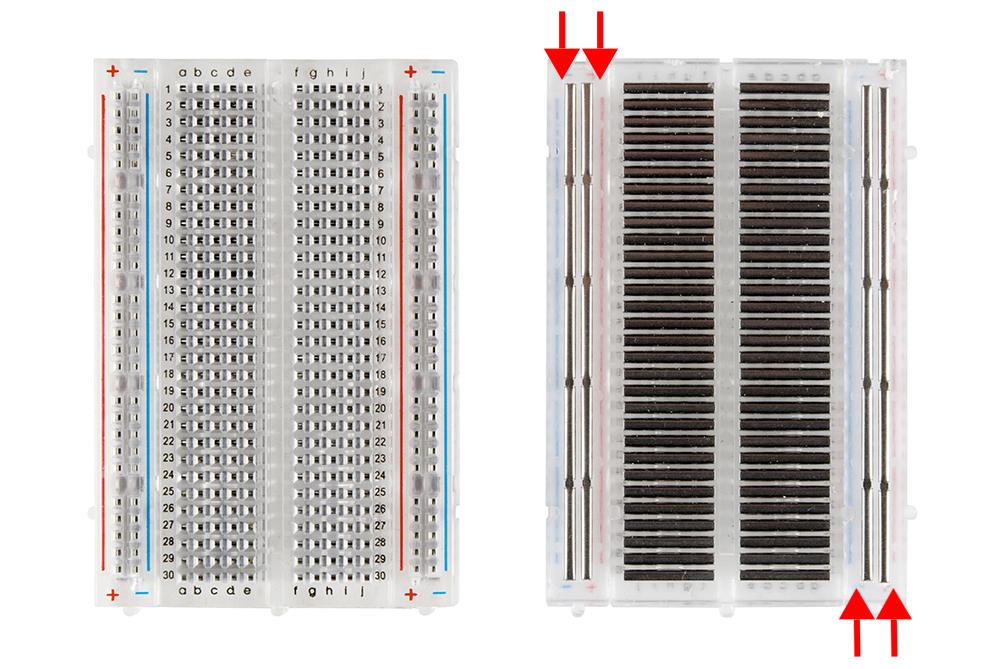
518c0b34ce395fea62000002.jpg (1000×669)

Series

Parallel

Button

Series with Button

Parallel with Button


Digital Read and Write:

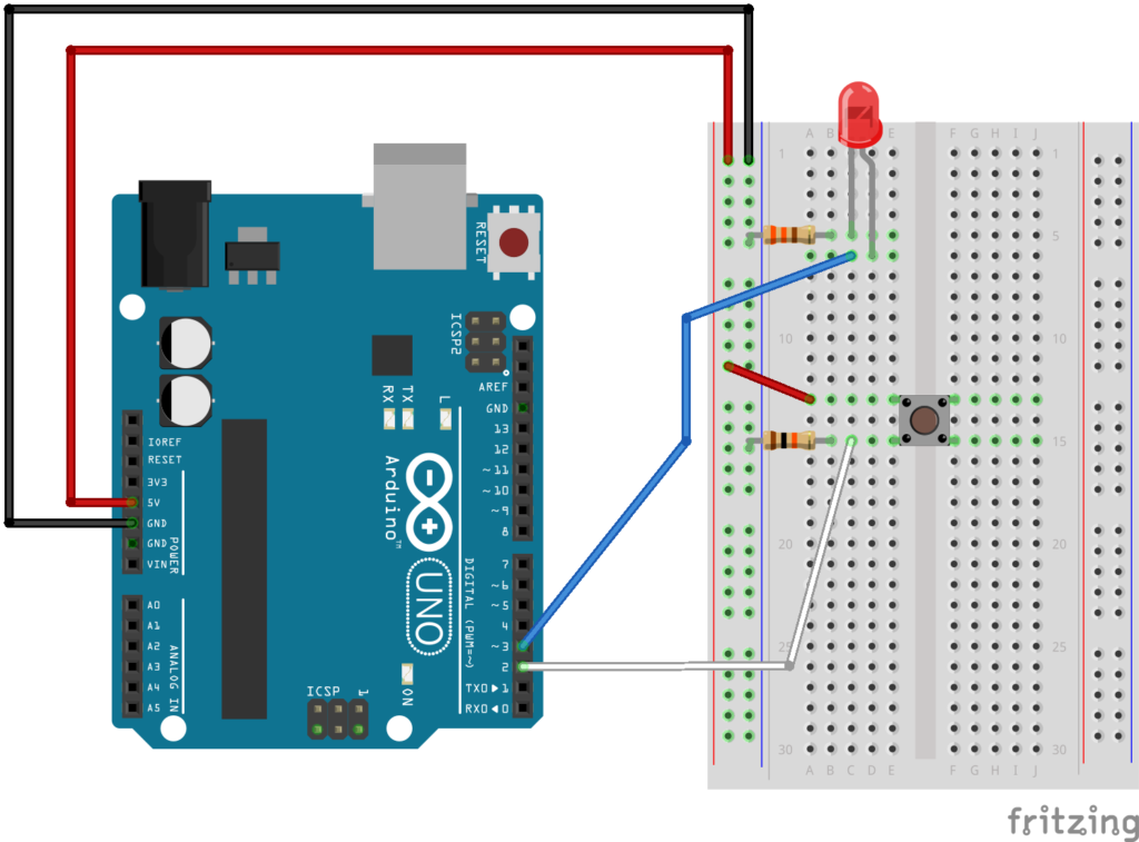
Digital Read a button on pin 2 and digital write an LED on pin 3:

Remember to include a 330 ohm resistor for the LED and a 10k ohm pull down resistor to ground for the button.

int buttonPin = 2;
int ledPin = 3;
int ledState = LOW;
int prevButtonState = LOW;

void setup() {
  // set pin modes
  pinMode(ledPin, OUTPUT);
  pinMode(buttonPin, INPUT);
  // needed in order to start serial communication
  Serial.begin(9600);
}

// PSUEDO CODE:
// check if button is currently pressed
// if button is pressed then check to see if it was pressed during the last frame too
// (we need to remember our button state)
// if button is bressed and previous button is not pressed then flip our LED state

 void loop() {
  // check to see what state our button is in, and store that information
  int currentButtonState = digitalRead(buttonPin);

  // if the button is currently being prssed down, AND during the last frame is wasn't pressed down
  if (currentButtonState == HIGH && prevButtonState == LOW) {
      // flip the LED state
      if (ledState == HIGH){
        ledState = LOW;
      } else if (ledState == LOW){
        ledState = HIGH;
      }
  }
  // if you want to print out the LED state
//  Serial.println(ledState);

  // set our LED to turn on and off according to our variable that we flip above
  digitalWrite(ledPin, ledState);

  //we need to remember the state of our button for the next time through LOOP
  prevButtonState = currentButtonState;
}

Resistor Color Code Calculator

How to add code to your documentation

Click the {…} button to add code to your post:

You’ll then see this screen where you can paste your code in:For Processing code change the language to Java:

Once you’re done click Add and you’re all set. Easy!

int rectWidth = 8;

void setup() {
  size(640, 480);
  rectMode(CENTER);
}

void draw() {
  background(255);
  for (int x = 0; x<width; x+=rectWidth) {
    float center = height*.25;
    float amplitude = 100;
    float speed = .01;
    float granular = .001;
    float freq = (frameCount* speed) + (x * granular);
    float adjustedHeight = noise(freq);// between 0 & 1
    adjustedHeight -= .5;// between -0.5 & 0.5
    adjustedHeight *= amplitude;
    rect(x + rectWidth/2, center + adjustedHeight, rectWidth, 100);
  }
  for (int x = 0; x<width; x+=rectWidth) {
    float center = height - (height*.25);
    float amplitude = TWO_PI;
    float speed = .01;
    float granular = .001;
    float freq = (frameCount* speed) + (x * granular);
    float angle = noise(freq);// between 0 & 1
    angle *= amplitude; // between 0 & TWO_PI
    pushMatrix();
      translate(x + rectWidth/2, center);
      rotate(angle);
      rect(0,0, rectWidth, 100);
    popMatrix();
  }
}