Final Project: Pet-A-Butterfly

Concept and Inspiration

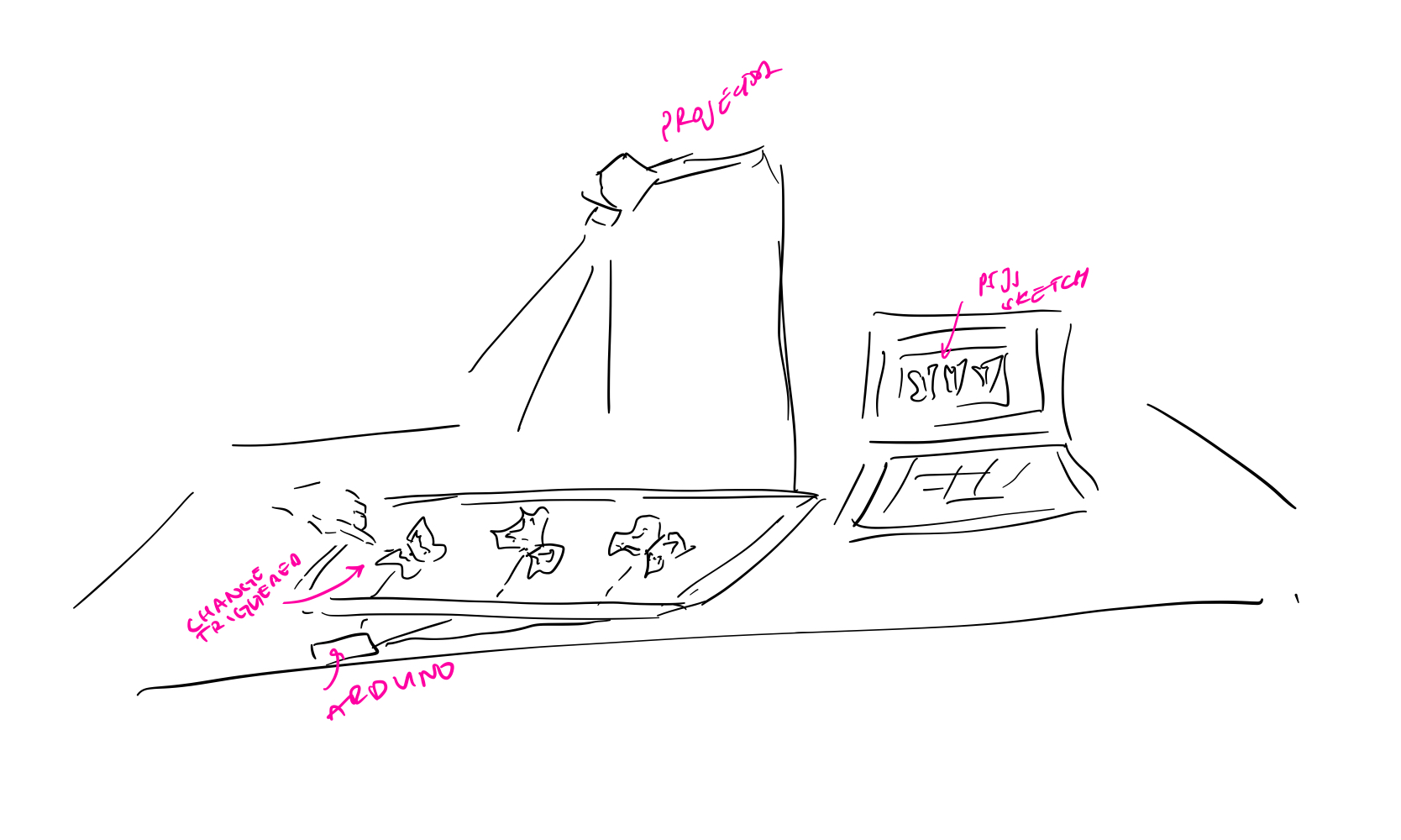
It was easy to come up with an overall abstract direction for the final project as I had set my mind early on to revisit the butterfly motif in different ways throughout the course. As for the actual concept behind the final, I wanted to experiment with something more centered around interaction and visuals in an installation-like manner and explore a new mode of design that I have not tapped into yet. After iterations and iterations of deliberations and conversations with Professor Aaron, I settled on creating a small piece centered around a mechanical butterfly that flutters when touched. The butterfly would be mounted atop a physical canvas, onto which p5-generated animations would be mapped and projected. The idea was to create a cohesive piece, with the hardware and the software working hand-in-hand to bring some life to a butterfly.

The mechanical butterfly is constructed out of two servo motors, with one moving at an angle supplementary to that of the other. The butterfly wings are printed on paper, laminated, cut, and attached to the servo motor blades. The butterfly “senses” touch through its antennas. My mechanical butterfly’s antennas are made of wires stripped, twisted to shape, and connected to a touch capacitive sensor. I used a box, which I wrapped with multiple layers of white paper and decorated with flowers (to look like the butterfly is in a flower field), with an opening for the Arduino and the circuit.

Interaction Design

For this piece, I wanted to emphasize designing a relatively simple interaction optimally well. The name I chose for the piece, “Pet-A-Butterfly” would be displayed to the user and would act as a signifier to touch the butterfly. The placement of the butterfly antennas opposite the user is intentional to maximize the probability that a user strokes the wires in the chance that they do not realize the antennas are to be touched. The user can interact with the piece by touching the butterfly antennas. Once touched, the butterfly wings flap, and a kaleidoscope of small p5-generated/projected butterflies emerge from beneath the butterfly and move outward in a synergistic, spiral motion.

Implementation
Arduino

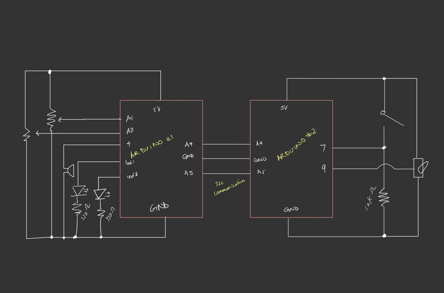
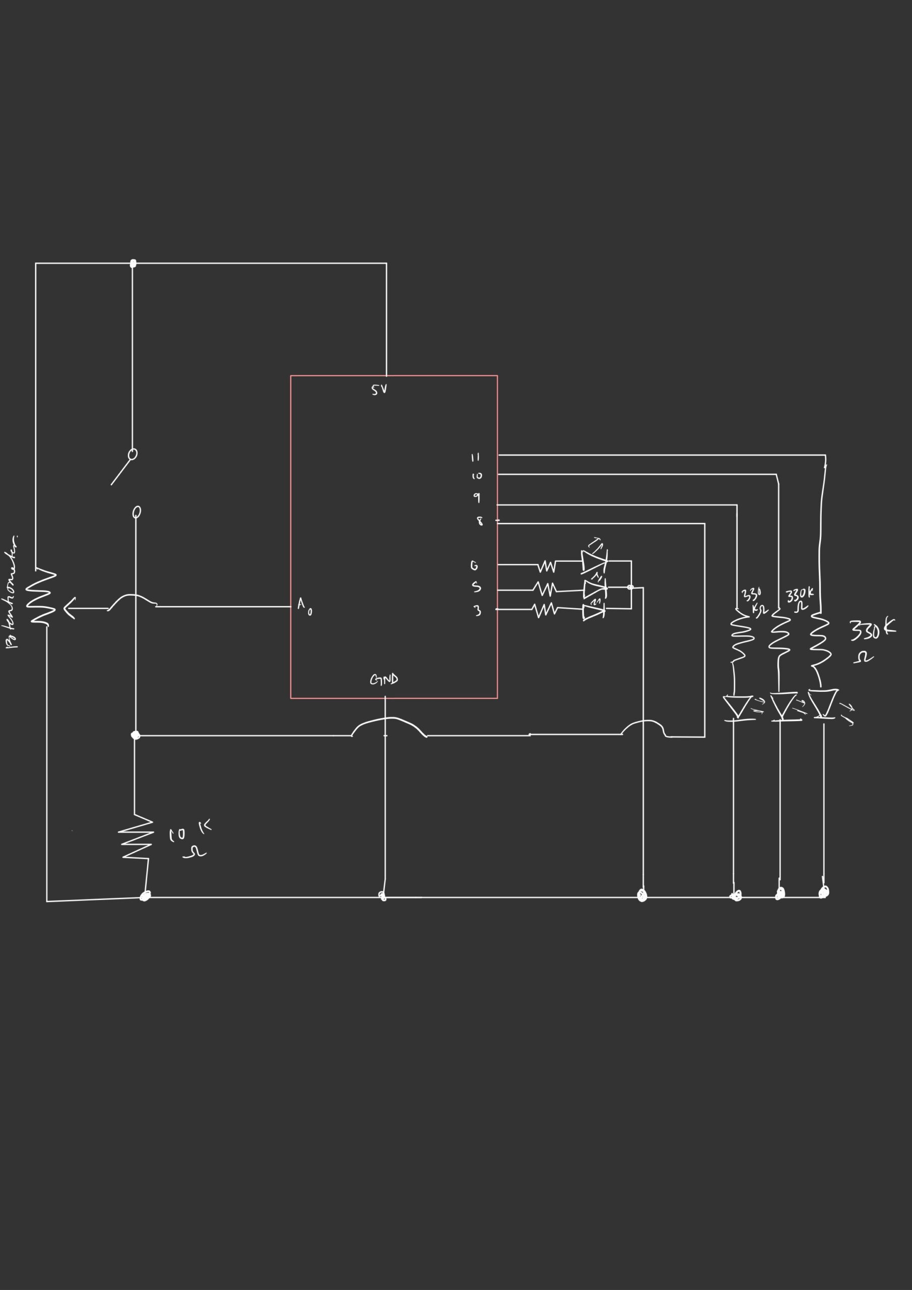
The Arduino program gets the input from the sensor through the touched()method, which returns an 8-bit value representing the touch state of all pins, and sends it to the p5 sketch through serial communication. The program also gets the current status of the butterfly movement from the p5 sketch program. If the status is 1 (the butterfly is moving), the servo motor positions are updated every interval seconds. The angles of the motors are constrained to the range [25,50] and the direction of each motor’s movement alternates after each range span to achieve the flapping movement. The Arduino program also sends the current servo position to the p5 sketch to ensure the sketch only stops the butterfly animation if the servos are in the maximum angle position, ensuring the flapping stops when the wings are maximally spread.

Below is the full Arduino sketch: 

/*************************************************** 
  This is a library for the CAP1188 I2C/SPI 8-chan Capacitive Sensor

  Designed specifically to work with the CAP1188 sensor from Adafruit
  ----> https://www.adafruit.com/products/1602

  These sensors use I2C/SPI to communicate, 2+ pins are required to  
  interface
  Adafruit invests time and resources providing this open source code, 
  please support Adafruit and open-source hardware by purchasing 
  products from Adafruit!

  Written by Limor Fried/Ladyada for Adafruit Industries.  
  BSD license, all text above must be included in any redistribution
 ****************************************************/
 
#include <Wire.h>
#include <SPI.h>
#include <Adafruit_CAP1188.h>
#include <Servo.h>

// Reset Pin is used for I2C or SPI
#define CAP1188_RESET  9

// CS pin is used for software or hardware SPI
#define CAP1188_CS  10

// These are defined for software SPI, for hardware SPI, check your 
// board's SPI pins in the Arduino documentation
#define CAP1188_MOSI  11
#define CAP1188_MISO  12
#define CAP1188_CLK  13

#define CAP1188_SENSITIVITY 0x1F
// For I2C, connect SDA to your Arduino's SDA pin, SCL to SCL pin
// On UNO/Duemilanove/etc, SDA == Analog 4, SCL == Analog 5
// On Leonardo/Micro, SDA == Digital 2, SCL == Digital 3
// On Mega/ADK/Due, SDA == Digital 20, SCL == Digital 21

// Use I2C, no reset pin!
Adafruit_CAP1188 cap = Adafruit_CAP1188();

// Or...Use I2C, with reset pin
//Adafruit_CAP1188 cap = Adafruit_CAP1188(CAP1188_RESET);

// Or... Hardware SPI, CS pin & reset pin 
// Adafruit_CAP1188 cap = Adafruit_CAP1188(CAP1188_CS, CAP1188_RESET);

// Or.. Software SPI: clock, miso, mosi, cs, reset
//Adafruit_CAP1188 cap = Adafruit_CAP1188(CAP1188_CLK, CAP1188_MISO, CAP1188_MOSI, CAP1188_CS, CAP1188_RESET);

// make a servo object
Servo servoRight;
Servo servoLeft;

// servo pposition 
int position=50; 
// direction of wing movement
boolean direction = true;  

unsigned long previousMillis = 0;
const long interval = 100;  // interval between each wing flap in milliseconds

void setup() {
  Serial.begin(9600);
  Serial.println("CAP1188 test!");

  // Initialize the sensor, if using i2c you can pass in the i2c address
  if (!cap.begin(0x28)) {
  if (!cap.begin()) {
    while (1);
  }
  cap.writeRegister(CAP1188_SENSITIVITY, 0x5F);
  // attach the servo to pin 9 
  servoRight.attach(11); 
  servoLeft.attach(5); 
  // write the position 
  servoRight.write(180- position);
  servoLeft.write(position);
  // // start the handshake
  while (Serial.available() <= 0) {
    digitalWrite(LED_BUILTIN, HIGH); // on/blink while waiting for serial data
    Serial.println("0"); // send a starting message
    delay(300);            // wait 1/3 second
    digitalWrite(LED_BUILTIN, LOW);
    delay(50);
  }
}
}

void loop() {
  // wait for data from p5 before doing something

  while (Serial.available()) {
    uint8_t touched = cap.touched();
    int isMoving = Serial.parseInt(); // check if butterfly is still moving 
    Serial.print(touched); 
    Serial.print(',');
    if (isMoving == 1) {
        unsigned long currentMillis = millis();
        // check if it's time to update the wing position
        if (currentMillis - previousMillis >= interval) {
            // move servos to simulate wing flapping motion
            if (direction) {
                position += 10;
                if (position >= 50) { // flip direction twhen max angle is reached
                    direction = false;
                }
            } else {
                position -= 10;
                if (position <= 25) {
                    direction = true;
                }
            }
            // move servos in opposite directions 
            servoRight.write(180-position);
            servoLeft.write(position);

            previousMillis = currentMillis;
          }
      };
    Serial.println(position); // send servc position to p5 sketch 
  }
  digitalWrite(LED_BUILTIN, LOW);
}


P5

The p5 sketch is mainly responsible for triggering the animation of the smaller butterflies and for performing projection mapping which is essential for ensuring that the canvas of the sketch can always be calibrated to fit the surface of the physical box. For the latter, I made use of the p5.mapper library to create a quad map that could be calibrated to match the aspect ratios of the box’s surface dynamically. By pressing the ‘c’ key, the map’s points can be toggled and moved appropriately. This eliminated the challenge of having to align the projector height consistently across locations and manually configuring the sketch’s canvas dimensions to match the surface. After calibrating the map, the p5 program can save the map in a json file to be loaded with every program run by pressing the ‘s’ key. This code snippet of the setup()function shows how to initialize a map object and load an existing map configuration.

function setup() {
  createCanvas(windowWidth, windowHeight, WEBGL);
  
  // create mapper object
  pMapper = createProjectionMapper(this);
  quadMap = pMapper.createQuadMap(mapWidth, mapHeight);
  
  // loads calibration in the "maps" directory
  pMapper.load("maps/map.json");

  // initialize objects
  bigButterfly = new Butterfly(
    centerX,
    centerY,
    null,
    null,
    null,
    null,
    null,
    false,
    false,
    null,
    null,
    false
  ); // dummy butterfly object simulating the state of the physical butterfly 
  interaction = new Interaction(); // an interaction object that handles all interaction-related animations 
  
  // play background music in loop
  backgroundMusic.loop(); 
}

To implement the animation, I created an Interaction class that would start and display the animation of the butterflies in a method called play(). This method would be the argument to a function of the pMapper object called displaySketch that would handle displaying the sketch only within the map’s bounds.

// class that controls the animation trigger by the interaction 
class Interaction {
  constructor() {
    this.bigButterfly = bigButterfly; // the butterfly object containing information about the physical butterfly in the center
    this.smallButterflies = []; // array that stores the smaller butterflies whose animation is triggered and displayed when signal is received from arduion
    this.numButterflies = 100; // number of small butterflies 
    this.inTheCenter = this.numButterflies; // number of butterflies in the center 
    // initialize randomly colored butterfly objects and append to the smallButterflies array 
    let randomNum;
    for (let i = 0; i < this.numButterflies; i++) {
      randomNum = random([1, 2, 3]);
      if (randomNum == 1) {
        this.smallButterflies.push(
          new SmallButterfly(
            centerX,
            centerY,
            smallButterflySpritesheet2,
            4,
            10,
            0,
            3,
            true,
            false,
            null,
            null,
            false
          )
        );
      }
      else if (randomNum == 2){
        this.smallButterflies.push(
        new SmallButterfly(
            centerX,
            centerY,
            smallButterflySpritesheet1,
            4,
            10,
            0,
            5,
            true,
            false,
            null,
            null,
            false
          )
        ); 
      }
      else if (randomNum == 3){
        this.smallButterflies.push(
          new SmallButterfly(
              centerX,
              centerY,
              smallButterflySpritesheet3,
              4,
              10,
              0,
              13,
              true,
              false,
              null,
              null,
              false
            )
          ); 
      }
    }
  }

  play(pg) {
    /* function that controls that controls the sketch 
    display -> passed to mappper object's displaySketch function 
    */
    pg.clear();
    pg.push();
    pg.background(color("#B2D2A2"));
    // display instructions text only before connecting to serial 
    if (textShow){
        pg.push()
        pg.fill(color("#2c4c3b"))
        pg.textFont(font); 
        pg.textAlign(CENTER);
        pg.textSize(16)
        pg.text(textString, centerX+20, centerY+150);
        pg.pop()
    }

    // display butterflies
    for (let i = 0; i < interaction.numButterflies; i++) {
      pg.push();
      let angle = radians(180); 
      pg.translate(
        interaction.smallButterflies[i].x,
        interaction.smallButterflies[i].y
      );
      pg.rotate(angle); // rotate butterflies 180 degrees --> better visibility for the user 
      if (interaction.smallButterflies[i].moving) { // display the small butterfly if it's moving 
        pg.image(interaction.smallButterflies[i].show(), 0, 0, 40, 40);
        interaction.smallButterflies[i].move(); // update movement of butterflies 
      }
      pg.pop();
    }

    pg.push();
    
    // ellipse enclosing projected surface area of the physical butterfly
    pg.fill(color("#B2D2A4"));
    // pg.fill(color("black"))
    pg.noStroke();
    // pg.ellipse(215, 180, butterflyWidth, butterflyHeight)
    pg.pop();

    // stop butterfly from moving after a set time has elapsed and only if the 
    // position of the servo is in the right direction 
    if (millis() - movementTime >= interval && servoPos == 50) {
      bigButterfly.moving = false;
    }
  }
}

The movement of the butterflies follows a spiral-like path, originating outward and around the physical butterfly. It is implemented in a method of thesmallButterflyclass which inherits from a parent Butterflyclass. Here is a code snippet showing the implementation of the path movement in the smallButterflyclass :

move() {
  // update the step of the animation 
  if (frameCount % this.animationSpeed == 0) {
    this.step = (this.step + this.animationDir * 1) % this.numSpritesCol;
  }

  // control the direction of the sprite movement as spritesheet must be traversed back and forth to display correct movement 
  if (this.step == 0) {
    this.animationDir = 1;
  } else if (this.step == this.numSpritesCol - 1) {
    this.animationDir = -1;
  }
    // update the x and y positions based on the current angle and radius 
    this.x = centerX + cos(this.angle)* this.radius + random(-0.5,0.5); 
    this.y = centerY + sin(this.angle)* this.radius + random(-0.5,0.5);
    this.angle += this.angleSpeed; // increment angle to move the butterfly along a circular path 
    this.radius += this.radiusSpeed; // increment the radius to move the butterfly outward 

  
  // move back to center if butterfly exceeds the bounds 
  if (this.x < minX || this.y < minY || this.x > maxX || this.y > maxY) {
    this.x = centerX;
    this.y = centerY;
    interaction.inTheCenter += 1; // butterfly is now counted as being in the center
    this.moving = false; // stop butterfly from moving 

  // update angle and radius speed parameters to random values 
    this.angleSpeed = random(-0.02, 0.02);
    this.radiusSpeed = random(0.5,1.2);
    this.angle = 0; 
    this.radius = 0; 
  }
  // flip butterfly direction depending on location in the sketch 
  if (this.x < centerX && this.sprites.length > 1) {
    this.dir = 1;
  } else {
    this.dir = 0;
  }
}

When the p5 sketch receives the touch state and servo position from Arduino, it sets the moving attribute of both the butterfly object simulating the physical butterfly in the sketch and the small butterflies to true. It also starts the timer, as the physical butterfly should only stop moving after 6 seconds have elapsed and if the servos are in the right position:

function readSerial(data) {
  ////////////////////////////////////
  //READ FROM ARDUINO HERE
  ////////////////////////////////////

  if (data != null) {
    // make sure there is actually a message
    let fromArduino = data;
    // if the right length, then proceed
    if (fromArduino.length > 0) {
      // get value only when data sent from arduino is greater than 0
      fromArduino = split(trim(fromArduino), ",");
      touchSensorVal = int(fromArduino[0]); // get touch sensor val
      servoPos = int(fromArduino[1]); // get servo pos
      if (touchSensorVal >= 1) { // if sensor is touched, set the bigButterfly moving attribut to true 
        interaction.bigButterfly.moving = true;

        movementTime = millis(); // record starting movement time
        interaction.inTheCenter = 0;
        // move smaller butterflies 
        for (let i = 0; i < interaction.numButterflies; i++) {
          interaction.smallButterflies[i].moving = true;
        }
      }
    }

    //////////////////////////////////
    //SEND TO ARDUINO HERE (handshake)
    //////////////////////////////////
    let sendToArduino;
    if (interaction.bigButterfly.moving == true) {
      sendToArduino = 1 + "\n"; // send 1 to Arduino if the butterfly is moving 
    } else {
      sendToArduino = 0 + "\n"; // send 0 to Arduino if the butterfly is done with its animation 
    }
    writeSerial(sendToArduino);
  }
}

Here is an embedding of the full sketch (you can press the ‘d’ key to play the animation without the signal from Arduino):   


Reflections and Parts I am Proud of

My biggest concern going into this, especially as I was going to employ projection mapping, was that I would be unable to align the p5 sketch and the physical butterfly together in a cohesive manner that still looks visually pleasing. I am, thus, proud that the final product resembles what I had envisioned. I also spent a lot of time thinking of the proper mechanism to automate the wing flapping motion and where/how to place the wings. I experimented with a lot of methods, such as attaching a vertical straw/wooden stick from the middle of the wings to the servo blades, and tugging on the wings when moving down to move the wings up and down. When that proved to be unhelpful, I switched to simply attaching each wing to a blade, which, in hindsight, should have been what I experimented with first. I also love the detail of having the connection between the butterfly and the sensor be through antenna-looking sensors, resembling the sense mechanisms of an actual butterfly (thanks to Professor Aaron for pointing this out). Finally, I am proud that I managed to properly calibrate the sensitivity of the touch sensor, as it initially was too sensitive, sometimes even detecting signals even when untouched. Keeping the sensitivity in check was a major challenge that I thankfully was able to overcome to keep the interaction consistent.

Areas for Future Improvements

I think the project could definitely be enhanced in a lot of ways. Because I spent a lot of time putting the interface together, an area of future improvement could be the p5-generated animation itself. I could have different path movements triggered with every touch, for example. I had initially wanted to map an actual animated butterfly from p5 onto a blank silhouette cutout of a butterfly, controlled by the servos in the same way. Because of difficulties in mapping the software animations to the movement of the hardware, I decided to pivot toward having the central butterfly be completely in hardware form.  One improvement to explore is going in that direction, where I effectively add physical objects, like flowers, on the surface of the box and map simpler, more limited animations onto them.


Final Project User Testing

For user testing, I asked two of my friends to come in and try interacting with my piece. I have so far managed to bring everything together: 1) construct the box that would come to enclose the Arduino and whose surface would act as a canvas for the sketch to be projected on, 2) make the butterfly body out of printed laminated paper and attach the wings to the servos, 3) secure the butterfly atop the surface, and 4) attach two wires, shaped like butterfly antennas, beneath the wings to convey touch signals to the p5 sketch and activate the animation and the butterfly flutters. I knew that upon seeing the piece, users might not get the intuition to touch the butterfly. They also might shy away from touching it, out of fear of ruining the butterfly’s delicate structure, or assume that some other automatic process would have to trigger the movement of the piece. To counter that, I will be displaying a name next to my piece that indicates, but does not outright reveal, that a touch signal is necessary. I have not yet settled on a name, but have told my two friends that it would be called “catch a butterfly” or “pet a butterfly” and they immediately figured out that they had to use their hands in some way. I placed the antennas facing them so that they were more likely to come into contact with them and I was glad that they did end up placing their touch close enough to the wires for the signal to be captured.

They both loved seeing the butterfly in action, but gave the following feedback, which was mainly focused on the sketch itself:

  1. add different colors to the butterflies in the sketch
  2. experiment with different movement paths for the projected butterflies (inward movement from outside the sketch bounds or having multiple center points for their emergence, for example) or smoothen/slow down their movement.

I expected the feedback I got from them, as I have been planning to implement those two features after I had the basic version of the project implemented. I will be working on that over the next couple of days, as well as decorating the surface some more (adding flowers to cover the base of the servos and on different parts of the surface).

Week 12: Final Project Proposal & Progress

Concept

For my final project, I am yet again choosing to go with a butterfly theme. This time, however, I plan to give it a little life – in the real physical sense. With the ability of bringing hardware components together, and controlling them programmatically, we can simulate many things. I will attempt to do just that and bring a little life to a small butterfly.

My final project will essentially be a physical, mini-interface with a butterfly that reacts to human touch. The interface will display a butterfly atop a flower, undisturbed and resting peacefully. Once touched, its wings will flutter, awakening a swarm of butterflies that begins to flap away from beneath. The interface itself will be a physical surface on a table, with the animation, designed and implemented in p5.js, projected onto it. The interface will have a physical butterfly prototype (made from paper and laminated, perhaps) protruding in the middle. Once a sensor (a capacitive touch sensor) that is connected to it senses a signal, its wings will be activated and so will the butterflies’ animation in the backdrop. Its wings will be attached to two servo motors that will move once a signal is received from p5.

Materials and Hardware

  1. Arduino Uno and breadboard
  2. Capacitive touch sensor
  3. Two servo motors
  4. A general-purpose tripod
  5. A projector

p5.js

The p5.js sketch is responsible for creating and controlling the animation. For the creation of butterfly objects, I tried experimenting with generative art, but it proved to be quite challenging as I needed to simulate the smooth motion of flapping wings. I, hence, will be using standard images (spritesheets) to display the graphics. The p5.js sketch will consistently read the messages transmitted from the Arduino program, waiting for a touch signal to activate the motion of the butterfly wings and the subsequent animation. Once the animation begins, it will send messages to the Arduino program, communicating that the animation is still underway. These messages are going to be used to keep the servo motors, controlling the wings, in motion. Once the animation stops, as indicated by all the smaller butterflies that escaped from beneath the central butterfly leaving the screen display, the sketch will send a terminating message to the Arduino, which will be used to bring the motion of the servos to a halt.

In order to ensure a seamless mapping experience between the sketch and the physical surface, I will be using p5.mapper. This library allows you to calibrate your sketches dynamically in order to match the dimensions of your sketch with that of a surface, once projected.

Arduino

The Arduino program will have a touch sensor as an input and servo motors as output. The touch sensor sends a signal to p5 indicating a touch is detected and will receive messages used to control the duration of the motor-controlled wing flaps.

Progress

p5

So far, I have the major parts of my sketch (the animation, serial communication, and projection mapping) completed for the most part. I want to work on the aesthetics of it a little more next and will have to modify the serial communication implementation to synchronize the movement of the motors.

https://editor.p5js.org/sarah-altowaity1/sketches/5eZkJXShI

Arduino

The main circuitry is wired up to connect the touch sensor and the motors. The program sends the sensor signal over to p5 for detection of touch. I, additionally, implemented the wing flap motion with the motors. However, I still need to work on the synchronization between the animation and the servo movements. I also need to figure out a way to conveniently and securely place the wings on the motor flaps and stabilize the components.

Sketch mapped onto a surface

Next Steps

The main next step is putting it all together and completing the technical aspects of synchronizing the animation with the physical components. I also need to work on designing a neat interface with stable components as I would like to reduce the overhead of setting up (and the possibility of things falling apart or out-of-sync) as much as possible.

Week 12: Serial Communication Assignment – Sarah & Redha

  1. Make something that uses only one sensor  on Arduino and makes the ellipse in p5 move on the horizontal axis, in the middle of the screen, and nothing on Arduino is controlled by p5

For this exercise, we used a potentiometer as our analog sensor. The Arduino program sends the reading from the sensor over to p5, where it is mapped to the range [ellipseWidth/2, canvasWidth-ellipseWidth/2]. The mapped value is then used to determine the x position of the center of the ellipse.  Since nothing on Arduino is controlled by p5, p5 sends dummy data that is ignored by p5 to maintain the two-way handshake.

// ===== P5 =========
let diameter = 60; 
let sensorVal; // read from p5 transmitted message 

function setup() {
  createCanvas(640, 480);
  sensorVal = 1023/2;
}

function draw() {
  background(220);


  if (!serialActive) {
    text("Press Space Bar to select Serial Port", 20, 30);
  } else {
    text("Connected", 20, 30);


  }
  fill(0);
  ellipse(map(sensorVal, 0, 1023, diameter/2, width-diameter/2), height/2, diameter, diameter)

}

// === ARDUINO ====
void loop() {
// wait for data from p5 before doing something
while(Serial.available()){
digitalWrite(LED_BUILTIN, HIGH); // led on while receiving data
int _ = Serial.parseInt(); // get dummy variable sent over by p5
if(Serial.read() == '\n'){
delay(5);
int sensor = analogRead(A1); // read sensor value
delay(5);
Serial.println(sensor); // send sensor value
}
}
digitalWrite(LED_BUILTIN, LOW);
}

2. Make something that controls the LED brightness from p5

For this exercise, we created a slider that controls the brightness of the LED. The range of the slider matches that of the LED analog value ranges, from 0 to 255. Hence, we only had to send that value over to the Arduino. Once received, the Arduino program writes that value to the LED PWM pin in an analog fashion. For visualization, our p5 sketch draws a circle whose diameter is proportional to the LED brightness.

// ===== p5 ======
let slider;

function setup() {
  createCanvas(640, 480);
  sensorVal = 1023/2;
  slider = createSlider(0, 255, 0);
}

function draw() {
  background(0);
  

  fill(0,0,255);
  noStroke();
  let diameter = map(slider.value(), 0, 255, 0, height); 
  ellipse(width/2, height/2, diameter, diameter); 

  fill(255);
  if (!serialActive) {
    text("Press Space Bar to select Serial Port", 20, 30);
  } else {
    text("Connected", 20, 30);
  }
}

function keyPressed() {
  if (key == " ") {
    setUpSerial();
  }
}

function readSerial(data) {
  if (data != null) {
    let sendToArduino = slider.value() + '\n';
    print(sendToArduino)
    writeSerial(sendToArduino);
  }
}

// ===== ARDUINO =====

void loop() {
  // analogWrite(leftLedPin, pwm); 
  // wait for data from p5 before doing something
  while (Serial.available()) {
    digitalWrite(LED_BUILTIN, HIGH); // led on while receiving data
    pwm = Serial.parseInt(); // get dummy variable sent over by p5
    if (Serial.read() == '\n') {
      delay(5);
      analogWrite(rightLedPin, pwm); 
      delay(5);
      Serial.println("0");
    }
  }
  digitalWrite(LED_BUILTIN, LOW);
}

3. Take the gravity wind example and make it so every time the ball bounces one LED lights up and then turns off, and you can control the wind from one analog sensor

We needed to establish bi-directional meaningful data exchange in this exercise. The first is to send the Arduino a signal from p5 when the ball hits the ground. This is done by checking if the bottom portion of the ellipse touches the canvas’s lower boundary position.y + mass/2 == height . If this evaluates to true, a signal of 1 is sent over. Otherwise, 0 is sent. When the Arduino program receives the signal, it turns the LED on or off accordingly. Similarly, the Arduino sends the value of the potentiometer (our chosen sensor) over to p5, where it gets mapped to the range [-1, 1]. The mapped value is set towind.x. The closer the potentiometer value is to the extremes, the stronger the wind effect on the ball. Sensor values below 512 also get mapped to negative values, and the ball motion trajectory goes leftward. Otherwise, the wind effect goes in the opposite direction.

// ===== p5 =======

let velocity;
let gravity;
let position;
let acceleration;
let wind;
let drag = 0.99;
let mass = 50;

let analogVal = 0; 
let dir = 0; 

function setup() {
  createCanvas(640, 360);
  noFill();
  position = createVector(width/2, 0);
  velocity = createVector(0,0);
  acceleration = createVector(0,0);
  gravity = createVector(0, 0.5*mass);
  wind = createVector(0,0);
}

function draw() {
  background(220);
  applyForce(wind);
  applyForce(gravity);
  velocity.add(acceleration);
  velocity.mult(drag);
  position.add(velocity);
  acceleration.mult(0);
  
  if (!serialActive) {
    text("Press S to select Serial Port", 20, 30);
  } else {
    text("Connected", 20, 30);
  }
  
  fill(0); 
  ellipse(position.x,position.y,mass,mass);
  if (position.y > height-mass/2) {
      velocity.y *= -0.9;  // A little dampening when hitting the bottom
      position.y = height-mass/2;
    }
}

function applyForce(force){
  // Newton's 2nd law: F = M * A
  // or A = F / M
  let f = p5.Vector.div(force, mass);
  acceleration.add(f);
}

function keyPressed(){
  if (keyCode==LEFT_ARROW){
    wind.x=-1;
  }
  if (keyCode==RIGHT_ARROW){
    wind.x=1;
  }
  if (key==' '){
    mass=random(15,80);
    position.y=-mass;
    velocity.mult(0);
  }
  if (key == 's') {
    // important to have in order to start the serial connection!!
    setUpSerial();
  }
}

function readSerial(data) {
  if (data != null) {
    // make sure there is actually a message
    let fromArduino = data; 
    // if the right length, then proceed
    if (fromArduino.length > 0) {
      analogVal = int(data);
      
    } 
    wind.x = map(analogVal, 0, 1023, -1, 1); 
    let sendToArduino; 
    if (position.y + mass/2 == height){
      sendToArduino = 1 + '\n'; 
    }
    else{
      sendToArduino = 0 + '\n'; 
    }
    
    writeSerial(sendToArduino);
  }
}


// ======= Arduino ====== 
void loop() {
  // wait for data from p5 before doing something
  while (Serial.available()) {
    digitalWrite(LED_BUILTIN, HIGH); // led on while receiving data
    ledState = Serial.parseInt(); // get ball bounce indicator from p5.js
    if (Serial.read() == '\n') {
      // turn on LED accrodingly 
      if (ledState == 1){
        digitalWrite(rightLedPin, HIGH);
      }
      else{
        digitalWrite(rightLedPin, LOW);
      }
      
      currSensorVal = analogRead(A1); // read sensor value 
      Serial.println(currSensorVal); // send sensor value 
    }
  }
  digitalWrite(LED_BUILTIN, LOW);
}


Week 12: Design Meets Disability

One of the many things I appreciated about this week’s reading is how expansive and detailed its exploration of the relationship between design and disability is. Indeed, for a long time, designing for disability, as a discipline or practice, was brushed aside and accessibility was achieved merely by asking what augmentations need to be introduced to allow certain groups of people with disabilities the ability to use a platform or a product. The chapter begins by examining products built for those with disabilities and the role of fashion and artistic designers in normalizing and destigmatizing these products, effectively engulfing designs for those with disabilities into the wider culture of “mainstream” fashion. This latter inclusion affords people with disabilities both the luxury of choice and the long-awaited pleasure of finally being seen, both of which are things most people take for granted. We can see this sentiment reflected in the desire of athlete and model Aimee Mullins to find prosthetics that are “off-the-chart glamorous.” Incorporating artists in conversations about design for disability, which have been largely dominated by those with clinical and engineering backgrounds, is imperative in finding the sweet spot between functionality and aesthetics. I believe it is, however, important that those who are designing for disability are keen on involving the target user in their design process – the same way they would be if they were designing for any other target audience.

Interweaved within this aforementioned discussion is an emphasis on language. Integrating such designs into fashion means integrating them into a larger system of cultural artefacts, one of which is language. I enjoyed the delineation of the linguistic evolution of “spectacles” to “eyewear”. “Patients” become “wearers”.  The term “HearWear” is proposed in place of “hearing aids.” These are illustrations of how designers can actively contribute to changing cultural and societal outlooks, which is an essential prerequisite for actualizing inclusion.

One belief I held prior to reading this chapter was that designs had to be universally inclusive. After all, what is so difficult about ensuring that we have a multimodal interface that can accommodate all users? What I failed to realize is that additive complexity, as was pointed out by the article, would potentially create unintended inaccessibility. The idea of designing appliances and platforms that are effectively “flying submarines” is bound to leave us with an influx of products that are overly intricate, but with subpar performance in any singular task. It seems like what we need is a diversity of robust designs and products, for each type of user, that can perform their intended tasks optimally with elegant simplicity. We can only begin to reframe how we think of designing for disability – designing for inclusion – by inviting more than just engineers, whose aim is merely to achieve functionality and problem-solving, into the conversation.

Week 11: Final Project Concept

For my final project, I would like to revisit generative art – especially since I really enjoyed the immersive nature and the aesthetic satisfaction that comes with making such works. And to stay true to the original thread that ran through a lot of my work this semester, I am deciding to once again incorporate butterflies. Since my midterm project was essentially a game, I want to pivot toward making an artistic piece. Thanks to Professor Aaron, who helped me sift through a bunch of ideas and finalize an initial concept, I am currently set on building a miniature installation with butterflies whose movements or shapes are activated/manipulated through touch. Essentially, I would make (perhaps fabricate, if time allows) butterflies and disperse them on a physical canvas. Each butterfly on the physical canvas would be connected via conductive material to a touch capacitive sensor. Using p5.js, I would create and control the butterflies’ shapes, colors, and animations. The p5.js sketch would then be projected and mapped onto the physical canvas. Sensory touch signals relayed by the Arduino would trigger a change in the animation/shape/color of the touched butterfly on the p5.js sketch and, by extension, the physical canvas.

Here’s a very rough visualization of what I have in mind:

Week 11: Musical Instrument – DJ Set [Sarah & Rama]

Concept

As I was playing around with playing tones using the Arduino last week, I couldn’t help but think that the combination of potentiometers and buttons, leftover from my last project, alongside the buzzers, resembled a DJ set. This was what Rama and I ended up going with for this week’s assignment. The set is built using two potentiometers, a digital switch, a piezo buzzer, servo motors, and two LEDs (for visual feedback). When connected to power, the set produces a melody that the player (DJ) can manipulate by using the first potentiometer (which controls the pitch) and the second potentiometer (which controls the tempo). The red LED blinks in sync with the tempo set by the second potentiometer. The yellow LED’s brightness is proportional to the pitch (the higher the pitch, the higher the brightness).  The servo motor resembles the turntables on an actual DJ set. You can activate it by pressing the digital switch. Upon activation, the servo motor will rotate at a speed equivalent to the beat’s tempo.

Implementation 

Effectively, the DJ set plays a sequence of notes in succession, stored in a global 2D array, whose pitch class and the tempo of the beat are controlled by the potentiometers. In switching successively between tempos and pitch classes, the player generates different tunes and overall musical moods. The player can also switch on the servo motor, whose position incrementally increases at the same rate set by the tempo the player chose.  We utilize two Arduinos, one controlling the sound manipulation between different tempos and pitches using the potentiometers (as well as the LED) and the other controlling the servo motor via a switch. The first Arduino sender program sends the position of the servo motor at time intervals corresponding to the current rate set by the tempo, using the Inter-Integrated Circuit (I2C) Protocol, over to the second Arduino. The receiver program on the second Arduino receives the position and updates the location of the servo, conditional on the button state being on. As the first receiver program also needed to synchronize sound with the blinking of the LEDs, it was essential to extrapolate the concept of blinking without delay to the playing of tones by the buzzer.

Code Snippets

The sender Arduino program sets up a connection using the Wire library in the setup().

void setup() {
  pinMode(led0, OUTPUT); 
  pinMode(led1, OUTPUT); 
  Wire.begin(); // set up I2C communication 
  Serial.begin(9600); 
}

The sender Arduino program reads the two potentiometer values, using the first value to control the pitch (by mapping the value to the range 0-3, corresponding to the range of sequences in the global notes array ) and the second to control the tempo/rate of playing a note. The first value is used to index the 2D array,notes[][], which stores the sequence of notes in different pitches. It also sets the brightness of the yellow LED. The second is used to index the duration[] array, which specifies the rate at which notes are played. The notes in the array notes[potVal1] are played in succession, with the next note in the sequence playing if the specified duration has passed. The state of the red LED is updated to blink according to the rate of the current melody being played. Finally, the position of the servo motor is also updated and sent to the second Arduino program.

void loop() {
  // get potentiometer values
  int potVal1 = map(analogRead(potPin1), 0, 1023, 0, 3); // control pitch
  int potVal2 = map(analogRead(potPin2), 0, 1023, 0, 3); // control tempo 

  // map the first potentiometer's value to the range [30,255] to control the brightness of the
  // yellow LED - higher pitch -> higher brghtness 
  int led0Val = map(constrain(analogRead(potPin1), 30,1023), 0, 1023, 30, 255); 
  analogWrite(led0, led0Val); // write the mapped potentiometer value to the LED pin 


  // get the duration (based on tempo) from the second potentiomenter 
  int duration = durations[potVal2];

  // check if time has elapsed since the last tone
  if (millis() - prevMillis >= duration * 1.60){
    prevMillis = millis(); // update previous time 
    led1State = !led1State; // update blinking state for the red LED
    digitalWrite(led1, led1State);
    tone(4, notes[potVal1][note], duration); // play tone that corresponds to the set frequency of the first potentiometer and for the duration set by the second potentiometer 
   
    note++; // cycle through the sequence 
    if (note >= 5) {
      note = 0; // Reset note index
    }

    // direction goes forward if position is at 0 
    if (position <= 0){
      servoDir = 1;
    }

    // direction goes backward if position is at 160 
    else if (position >= 160){
      servoDir = -1; 
    }

    position = (position+servoDir*20)%180;  
    Wire.beginTransmission(8); // begin transmission to receiver
    Wire.write(position);  // send over the positon of the servo motor 
    Wire.endTransmission();    // stop transmitting
    Wire.requestFrom(8, 6);    // request 6 bytes from receiver device #8
    delay(1); 
  }

}

The receiver Arduino program receives the position from the sender and updates the position if the switch state is set to 1 (the switch has been pressed to turn on the motor). Since the transmission occurs at a rate equivalent to the rate of the music, the motor will move according to the current tempo of the beat.

#include <Servo.h>
#include <Wire.h>

Servo servo; // initialize servo 
int x = 0; // variable storing data transmission 
int position = 0; // position of the servo motor 

const int switchPin = 7; // switch pin 
int buttonState = 0; // current button state 
int prevButtonState=0; // previous button state 
bool servoMove = false; // keeps track of the switch state 

void setup() {
  Serial.begin(9600);
  pinMode(switchPin, INPUT); 
  servo.attach(9);
  Wire.begin(8); 
  Wire.onReceive(receiveEvent); // initialize event triggered on receipt of data 
  Wire.onRequest(requestEvent); // initialize event on being requested data 
}

void receiveEvent(int bytes) {
  x = Wire.read();
  // validate received data
  if (x >= 0 && x <= 180) {
    position = x; // x directly maps to servo position
  }
}

void requestEvent()
{
  Wire.write("Hello ");
}

void loop() {
  buttonState = digitalRead(switchPin); 

  // maintain the state of the switch and use to determine if the motor should move
  if (buttonState == HIGH && prevButtonState == LOW){
    servoMove = !servoMove; 
  };

  // smoothly move the servo towards the desired position
  if (servoMove){
    if (position != servo.read()) {
      if (position > servo.read()) {
        servo.write(servo.read() + 1);
      } else {
        servo.write(servo.read() - 1);
      }
      delay(1); 
    };
  }

  prevButtonState = buttonState; 
}
Circuit Schematic

Here’s a schematic of our circuitry:

Demo


Reflections and Challenges

One of the things we struggled with, largely due to both of us lacking knowledge of musical compositions, is choosing the right sequence of tones that generate a coherent melody. With a combination of trial and error and some research, we found a suitable sequence. We also faced the challenge of one of our LED lights not turning on when we wired the servo motor to the same circuit. Instead of adding a second power source to connect the servo motor to, we opted to utilize I2C since we had an additional Arduino, which proved to be a useful exercise. Overall, we were happy with the final product, but I think it would be nice to extend this project further and give the player a little more creative control as the current setup is quite restrictive in terms of what final melodies the player can generate. For instance, we can have additional buzzers, each producing a different tone, controlled by switches that the users can use to make their own tunes from scratch over a set beat (something like a MIDI controller? ) .


Week 11: A Brief Rant on the Future of Interaction Design & Follow-Up Article

In my Spring semester of last year, I took a class called “Touch” that opened my eyes not only to the primacy of touch, but also to our consistent ignorance of the primacy of touch. Our tactile sensory system is the first to develop in the womb and is arguably the last to deteriorate as we get older. It is also the only reciprocal sense – we can only touch something if it touches us – providing us with a truly connective interface to interact with the diverse environments around us. The sense of touch is also extremely vital for normal cognitive and social development. Yet, prototypes of future technological interfaces reduce the full range of interaction that touch affords us or eliminate it altogether. The future vision for AR/XR technologies seems to be doing away with the tactile. Pictures-Under-Glass, the moniker Victor aptly coins and uses in this week’s readings, technologies already offer us limited tactile feedback that only our fingertips enjoy. We now see the future of AR/XR interfaces, such as headsets utilizing eye movement tracking systems, heading toward a direction where the visual is prioritized. Our rich haptic system is left to atrophy in the process.

It is indeed worrying that we might reach a time when kids struggle to use a pen or open lids. In attempting to connect to the world via modern-day interfaces, it seems like we are disconnecting from it in important ways. There must have been interfaces that we could have envisioned that integrate all of our varied sensory systems, had we invested the time to make that a priority. Victor’s rant and his follow-up article were both written in 2011. 13 years later, his call to invest in research that centers the full range of human capabilities in the design of technological interfaces seems to have gone unanswered. We have yet to make our capabilities a priority in design, but that could change if we collectively dare to choose a different way of envisioning tomorrow’s technologies.


Week 10: Digital/Analog Input and Output – Guessing Game

Concept & Inspiration

For this assignment, my aim was to create a simple gamified experience that engaged the user. I used to play this intuition game with my sister where she would think of a random number and I would try to “read” her mind and guess what that number was. With context clues of how “warm” or “cold” my guess was, I would eventually be able to get to the correct answer. My circuit is effectively a realization of this in hardware form.

Implementation

The circuit is composed of one RGB LED, three LEDs, a potentiometer, and a momentary switch. The game starts with the user pressing on the momentary switch (the digital sensor), upon which the Arduino program initializes a random number to be guessed. Upon activating the circuit, the RGB LED lights up in a pink color, indicating that the game is underway. The user then has to guess the number by using the potentiometer (the analog sensor) to find the correct value. The blue LED is lit if the current guess is far away from the correct number. The red LED lights up if the user is within a close range of the answer (±100 in my implementation). Once the number is guessed, the green LED lights up and the game is won. If the game is won, the RGB LED light show starts to celebrate the win, with different colors illuminating in succession. The user can turn off all the LEDs and restart the game using the momentary switch.

Code Snippets

The function setColor controls the color of the RGB LED in an analog fashion. This function is called when the game is started using the switch to set the color of the RGB LED to pink, and when the game is won, transitioning the RGB LED from having a static color to a dynamic light show (implementation below). The principle of blinking without delay is used to ensure the RGB LED seamlessly transitions from one color to the next and that the user is able to turn off all the lights without lags using the momentary switch.

void setColor(int redValue, int greenValue, int blueValue) {
  analogWrite(redRGBPin, redValue);
  analogWrite(greenRGBPin, greenValue);
  analogWrite(blueRGBPin, blueValue);
}
if (won && gameState){
  if (millis()>timer){
    timer = millis()+interval;
    i = (i+1)%5; 
  }
  if (i == 0){
    setColor(255, 0, 0); // red
  }
  else if (i==1){
    setColor(0, 255, 0); // green
  }
  else if (i==2){
    setColor(0, 0, 255); // blue
  }
  else if (i==3){
    setColor(255, 255, 255); // white
  }
  else if (i==4){
    setColor(170, 0, 255); // purple
  }
}

The game logic occurs inside the loop function, where the potentiometer value is read and compared against the number to be guessed. The potentiometer controls which LED lights up based on its value’s distance from the correct number (blue if the guess is far away from the correct answer, red if the guess is close, and green if it is correct).

if (gameState && !won){
    setColor(227,50,121); // pink     
    if (abs(pentSensorVal - randNum) == 0){ // if number is guessed correctly
      digitalWrite(greenPin, HIGH); 
      digitalWrite(bluePin, LOW);
      digitalWrite(redPin, LOW);
      won = true; 
    }
    else if (abs(pentSensorVal - randNum) < 100){ // getting warmer 
      digitalWrite(greenPin, LOW); 
      digitalWrite(bluePin, LOW);
      digitalWrite(redPin, HIGH);
    }
    else{ // you are way off
      digitalWrite(greenPin, LOW); 
      digitalWrite(bluePin, HIGH);
      digitalWrite(redPin, LOW);
    }
  }
Circuit Schematic

Here’s the schematic of the wiring of the hardware components:

Demo

Reflections and Extensions

After last week’s reading, I wanted to focus more on the creative idea than the technical complexity of the hardware components. It proved to be quite challenging to think of building something creative with the input sensors and output devices that we have been using in class. I spent a lot of time ideating and the implementation portion was not as time-consuming, especially since I made sure to diagram the schematic and outline the software logic prior to wiring the circuit and connecting the Arduino. One thing that I should have anticipated, however, is how easy the game would be due to the limited directionality of the potentiometer. If you know that your guess is not correct by dialing the potentiometer all the way to the left, for example, the answer must be found by dialing it all the way to the right. To make the game a little harder, I made the trivial modification of adding a second potentiometer. The guess is considered correct if the sum of the potentiometer readings is within 50 of the number to be guessed. I increased the “warm” range from ±100 to ±500 as it was getting extremely difficult to play the game.

sum = pentSensorVal1 + pentSensorVal2; 
if (abs(sum - randNum) < 50){
  digitalWrite(greenPin, HIGH); 
  digitalWrite(bluePin, LOW);
  digitalWrite(redPin, LOW);
  won = true; 
}
else if (abs(sum - randNum) < 500){
  digitalWrite(greenPin, LOW); 
  digitalWrite(bluePin, LOW);
  digitalWrite(redPin, HIGH);
}
else{
  digitalWrite(greenPin, LOW); 
  digitalWrite(bluePin, HIGH);
  digitalWrite(redPin, LOW);
}

Admittedly, adding a second analog sensor introduced complexity that came at the expense of interpretability. It becomes harder to strategize one’s guesses, partly due to the nature of the potentiometer values being hard to track.  Perhaps using a display, like an LCD, to reveal the current potentiometer values would be helpful.


Week 10: Creative Reading Response

“Physical Computing Greatist Hits and (misses)” is a compilation of recurrent physical computing themes that are popular and integrated into many projects. Reading this article at this stage in the class was important for me as I contemplated the range of things one could do with a simple Arduino kit. I do indeed find myself quite compelled to ditch ideas that used common physical interaction principles because they were simply too common. Instead of thinking of the novel ways one could use an input to a sensor, I frequently found myself looking for the least used sensor to incorporate in my future projects. I realize now, after reading the article, that it is more important what one does with input from a human interaction, rather than focusing on the complexity of the circuitry or the parts used. It also allowed me to see the various ways in which one could combine different themes together to create original work (e.g. video mirrors and mechanical movements in Soyoung Park’s Waves of Leaves).

“Making Interactive Art: Set the Stage, Then Shut Up and Listen” establishes a necessary shift of perspective for those who are designing human-computer interactive pieces. As someone who grew up dabbling in artistic projects, from composing poetry in my journal to oil landscape paintings and abstract multi-media pieces to adorn the walls of my room, I reflect on the prescriptive nature of those early artworks. It centered me, the artist, in the meaning-making process of the art. My central focus in making them was that those who came into contact with them were able to easily discern what I wanted them to discern. Designing interactive art, however, involves the ability to make space for the audience to insert themselves into the piece. The trick lies in designing a piece that is effectively able to accommodate all the different reactions it garners. This involves being able to predict people’s possible responses, perhaps aided by some process of user testing, and planning accordingly. Providing users with precisely the minimum amount of guiding context that affords them a sense of agency that operates within the predefined parameters the piece was designed to accommodate is truly an art that is worth mastering.