My Self Portrait Created in Processing

Oh boy here it is!

Here is the code

int x, y;
float x2,y2,speedX, speedY;

void setup () {
  size (700, 850);
  x= width/2;
  y= height/2;
   x2 = 0;
 y2 = 0;
  speedX =2;
  speedY =5;
}

void draw() {
  background(255);
//  fill(255,150,0);
//quad(180,340,300,340,300,400,300,460);
//quad (180,640,300,300,300,400,600,460);
//fill (100, 205, 30);
//ellipse( 200, 500, 300, 200);
//ellipse(x, y, 100, 100);

//neck
fill(245,230,195);
  stroke(245,230,195);
  quad(230, 600, 500, 600, 470, 900, 180, 900);
  
  fill(220, 187, 153);
  stroke(237, 187, 153);
  quad(150, 700, 500, 700, 400, 800, 230,780);


//face
  fill(255,235,203);
  stroke(255,235,207);
  quad(150, 175, 600, 175,540, 680, 100, 680);
  quad(125, 225, 150, 175,175, 750, 100, 680);
  quad(125, 225, 175, 750,540, 680, 150, 680);
  quad(600, 175, 600, 300,540, 680, 400, 760);
  quad(150, 175, 600, 175,400, 760, 175, 750);


//eyes
  stroke(0);
  fill(255, 240, 240);
  arc(240, 350, 70, 70, PI, PI+PI);
  fill(255, 240, 240);
  
  arc(430, 340, 70, 70, 0, PI+QUARTER_PI, OPEN);
  arc(240, 560, 120, 0, PI+QUARTER_PI, PI);

//pupils
  fill(0);
  ellipse(430, 345, 15, 15);
  ellipse(240, 335, 15, 17);

//nose
  fill(255, 230, 211);
  stroke(255, 230, 211);
  quad(x-40, y, x-20, y- 130, x+10, y-120, y-60, y+60);
  //nose
  fill(245, 210, 200);
  stroke(245, 210, 200);
  quad(320, 475, x+50, 465, x+10, y-120, y-60, y+60);
  //nose
  fill(235, 200, 190);
  stroke(235, 190, 190);
  quad(320, 500, 320, y+40, 400, 460, 380, 500);
  //nose
  fill(255, 230, 211);
  stroke(255, 230, 211);
  quad(x-40, y+100, x-20, y- 130, x+10, y-120, y-60, y+60);

//left eyebrow
  fill(147,81,22);
  stroke(147,81,22);
  quad(190, 300, 280, 295, 300, 330, 210, 315);

//right eyebrow
  fill(147,81,22);
  stroke(147,81,22);
  quad(400, 310, 465, 300, 490, 330, 390, 325);

  stroke(0);
  line(x+10, y-120, y-60, y+60);
  line(y-60, y+60,x-40, y+100);

//top lip
  stroke(203, 67, 53);
  fill(203, 67, 53);
  quad(230, 580, 300, 570, 350, 600, 210, 600);

//top lip
  stroke(203, 67, 53);
  fill(203, 67, 53);
  quad(250, 600, 350, 565, 400, 590, 410, 600);

//bottom lip
  stroke(236, 112, 99);
  fill(236, 112, 99);
  quad(210, 600, 410, 600, 370, 630, 270, 640);

// left ear
  stroke(237, 187, 153);
  fill(237, 187, 153);
  quad(80, 390, 120, 360, 110, 480, 90, 460);
  
  
//right ear
  stroke(237, 187, 153);
  fill(237, 187, 153);
  quad(580, 370, 620, 390, 640, 460, 570, 470);
  
 //hair
 fill(244, 208, 63);
 stroke(244, 208, 63);
 quad(350, 50, 500, 70, 650, 170, 390, 140);
 fill(244, 220, 80);
 stroke(244, 220, 80);
 quad(315, 70, 560, 125, 670, 260, 270, 190);
 fill(250, 240, 80);
 stroke(250, 240, 80);
 quad(201, 60, 320, 80, 390, 200, 170, 220);
 fill(255, 245, 100);
 stroke(255, 245, 100);
 quad(120, 80, 230, 100, 260, 210, 100, 230);
 
 ////fly
 //fill(15, 50, 30);
 //ellipse(x2, y2, 40, 20);
 //x2 += speedX;
 //y2 += speedY;
  
}

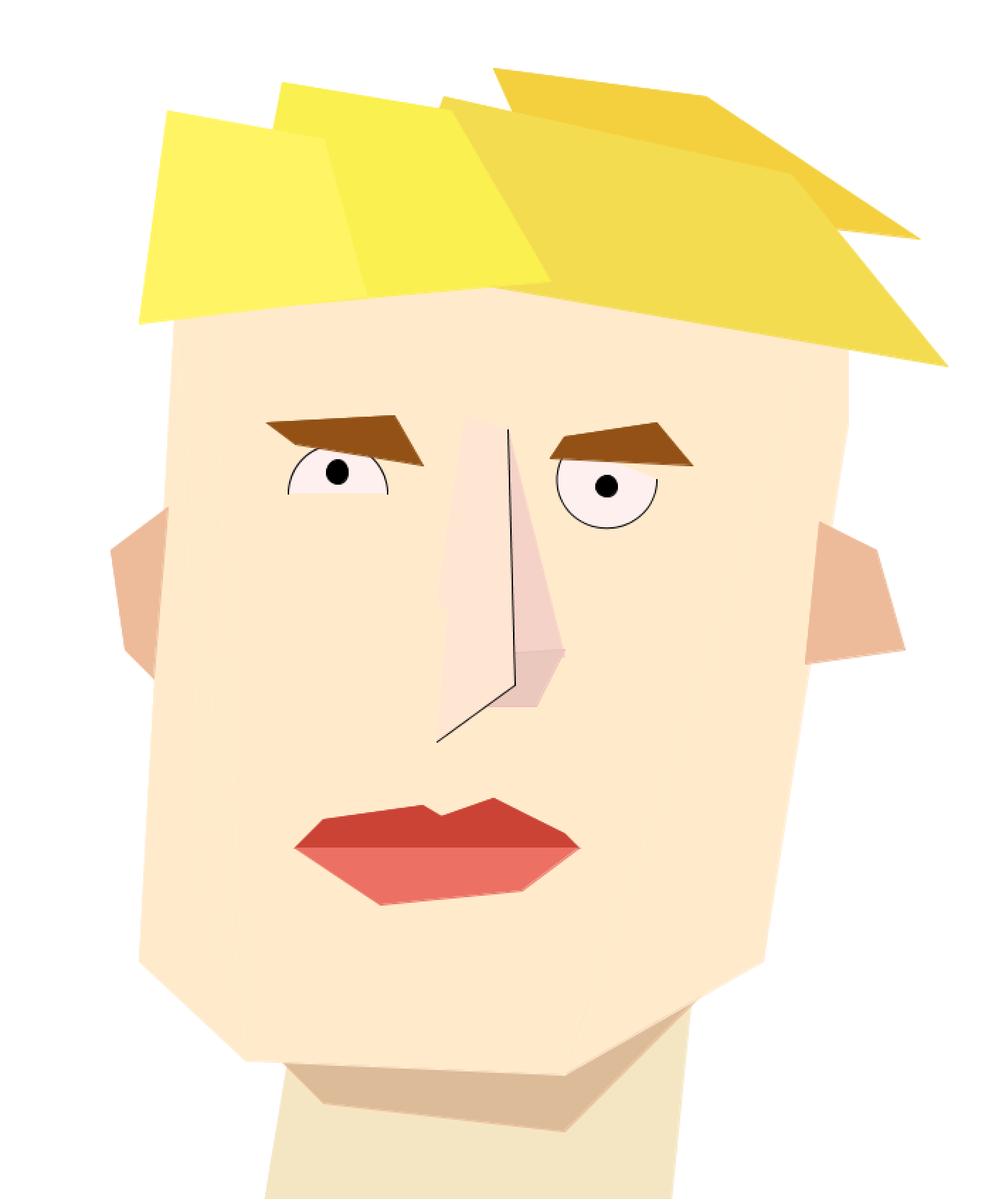
I used a lot of quad functions, because I thought it would most accurately represent the picasso-esque cubist ___ I desired.

I thought my portrait looked annoyed, so I was going to program a little fly to bounce around the screen, but ran out of time to make it as desired. I’m pretty happy with how it came out though.

Kyle reads “Physical Computing’s Greatest Hits (and misses)” by Tigoe

This blog post by Tom Igoe is basically a review of different physical computing or interactive media “themes.” These themes are different varieties of common physical computing projects. through the post he describes which ones have the most and least potential for artistic interpretation. As to not discourage the reader, Tigoe prefaces it by noting that despite the fact that  these themes exist and can be defined, it is still possible to find originality within the different interpretations of the themes.

What I think is helpful about his descriptions of the “themes” is that he not only explains how they work and how they are limited, but also provides examples of how to get past their basic functionality and make them original and interesting.

I think the thing that I enjoyed most about this post is that it got me excited about making my final interactive media project. I will definitely look back at this post if i need some inspiration for a place to start from. It might even be fun to combine multiple themes, like the author describes at the end of the post.

Kyle reads “Making Interactive Art: Set the Stage, Then Shut Up and Listen” by Tigoe

In this blog post, Tom Igoe describes the presentation of a piece of interactive arts as “The beginning of a conversation with the people who experience your work.” He introduces this concept to discourage other interactive media or physical computing artists from telling their audience blatantly how to interact with their artwork, rather than leaving physical suggestions as he would do.

It is like more classical artwork, like painting, in that you can the artist can give it whatever meaning they want, but what gives the artwork its meaning is what the viewer interacts with it. Each viewer sees the work through their own perspective, and thus has the power to give the artwork their own meaning. That is what art really is.

I believe that the author is attempting to defend interactive artwork as a craft, by connecting it to this meaning. He is educating other artists and telling them not to hand everything to their viewers, but to let them interpret it on their own.

 interactive artworks, are different from classical artwork in that the viewer interacts with them directly. Because of this, Tigoe suggests that there are specific strategies to making a piece of work physically discoverable. 

Here is a video of me playing with a highly discoverable interactive instillation at the Sydney Museum of Contemporary art last week.

Kyle Makes a Remote Controlled Crossbow

Hi I’m back to share some info about this cool project I did.

I have spent the last few weeks engineering this super cool remote controlled crossbow unit. The basic concept of the project was relatively simple: a crossbow controlled by 3 servo motors– two to position it in a 2 dimensional axis for aim, and another to release a crossbow bolt. I decided to use potentiometers to control the positioning servos, because it seemed most natural. I used a push button to release the trigger servo for the same reason.

All in all, the most time consuming part of the project was not coming up with or designing the unit, but engineering each piece of the crossbow to work in unison with every other. Since there were so many parts moving precisely in a free space, this was quite difficult,  especially since the unit needed to work repeatedly.

I decided that the way to allow the crossbow to move in space was to put it in a frame with servos pulling it from the edges of the frame. The vertical movement servo, connected to a small pulley wheel to reduce extraneous movement, pulled the crossbow up, while gravity would allow it to fall if the servo slacked tension. The horizontal servo, however, does not have gravity to counteract it, so I attached to opposite side to a spring that would create tension when pulled against.

Making everything the correct size with just scrap and a lack of proper tools (like a band saw) made it difficult. I spent a lot of time trying to overcome these problems.

One of the most difficult areas to fine tune was the trigger system. It was difficult to create a channel that not only held the crossbow bolt, but also was smooth enough to allow it to uniformly pass through the central hole in the cross bar. I decided to hot glue a plastic straw into a previously created channel in the wooden body of the bow. It took me quite a while to figure out a precise system that would allow the rubber band, which creates the force necessary to propel the bolt, to slide off the servo trigger and go straight into the notched end of the bolt. I used hot glue here like a makeshift 3d printer to make it so that the bolt would always lie in the right place.

In front of the bow I attached a board that a foam and cardboard target could be attached to.

The code was pretty simple for the most part. All I needed to do was connect my two potentiometers to the vertical and horizontal servo motors and make a button press.

#include <Servo.h>

const int vertPin = A0;

const int horzPin = A1;

int trigPin = 3;
int trigState = LOW;

Servo vertServo;
Servo horzServo;
Servo trigServo;

void setup() {
  // put your setup code here, to run once:
pinMode(trigPin, INPUT);
  vertServo. attach(9);
   horzServo. attach(6);
   trigServo. attach(11);

  Serial.begin(9600);
}

void loop() {
  // put your main code here, to run repeatedly:
  int vertState = analogRead(vertPin);
  int horzState = analogRead(horzPin);
  int trigRead = digitalRead(trigPin);

  int horzAngle = map(horzState, 0, 1023, 0, 180);
  int vertAngle = map(vertState, 0, 1023, 0, 180);

  vertServo.write(vertAngle);
  horzServo.write(horzAngle);

 Serial.print("read = ");
  Serial.println(vertState);
//  Serial.print(" Vertical = ");
//  Serial.println(vertAngle);
//  delay(100);
//  Serial.println(horzState);
//  Serial.print("Horizontal = ");
//  Serial.println(horzPin);

if (trigRead == LOW){
  trigServo.write (15);
} 
if (trigRead == HIGH) {trigServo.write(40);
}
}

I was concerned at first that my Arduino output did not have enough power to power all three servos simultaneously, but through experimentation, I found that I didn’t need to connect any external power.

I also found that I had a problem with crossing wires. I fixed this by braiding and twisting the wires connected to the remote controller and cleaning up the wiring of the breadboard in general.

I also had problems with syntax in my code, but once I fixed them, everything ended up coming together beautifully.

A Body of Music by Tori and Kyle

“What if you were the instrument?” A young, curly haired girl said to her best friend one rainy afternoon. Of course, it wasn’t actually rainy. It was Abu Dhabi.

And so, with that idea, Kyle and Tori set off on an adventure that woud use six sensors, four buzzers, one servo, and two solinoids, one fish bowl, one miscellaneous metal piece, and many wires to change the world.

This was a process and a half and took way too much time. Basically, we made an instrument in three different parts: percussion, piano, and maraca.

Percussion: consists of two solinoids attached to different materials, one a glass bowl and one a metal goblet type piece. It is attached to a muscle sensor. When Kyle flexes his muscle, a programmed beat begins.

Piano: consists of four pressure sensors attached to four buzzers. Each pressure sensor corresponds to two notes in the C major scale. At a low force, it plays one note and at a higher force it switches to another note.

Maraca: consists of one servo and one photoresistor attached to a tongue depressor. When the photoresistor changes its light reading, the servo moves and the maraca is shaken. We used a battery to balance the weights.

Here is our code. Kyle’s code is responsible for the percussion while my code is responsible for the maraca and piano. This is mainly because of issues with delay and balancing between the two boards.

Kyle’s Code:

int solenoidPin3 = 3;
int solenoidPin2 = 2;
const int analogInPin = A0;
int sensorValue = 0;        // value read from the pot
int outputValue = 0; 

void setup() {
  // put your setup code here, to run once:
pinMode(solenoidPin3, OUTPUT);
pinMode(solenoidPin2, OUTPUT);

Serial.begin(9600);
}

void loop() {
  // put your main code here, to run repeatedly:

sensorValue = analogRead(analogInPin);
  // map it to the range of the analog out:
  outputValue = map(sensorValue, 30, 700, 0, 100);

    Serial.print("sensor = ");
  Serial.print(sensorValue);
  Serial.print("\t output = ");
  Serial.println(outputValue);

  //get help figuring out the delay
  if (outputValue > 30) {
digitalWrite(solenoidPin2, HIGH);
delay(50);
digitalWrite(solenoidPin2, LOW);
delay(100);
digitalWrite(solenoidPin2, HIGH);
delay(50);
digitalWrite(solenoidPin2, LOW);
delay(100);
digitalWrite(solenoidPin2, HIGH);
delay(50);
digitalWrite(solenoidPin2, LOW);
delay(100);


digitalWrite(solenoidPin3, HIGH);
delay(100);
digitalWrite(solenoidPin3, LOW);
delay(200);
digitalWrite(solenoidPin3, HIGH);
delay(100);
digitalWrite(solenoidPin3, LOW);
delay(200);  

}
else if (outputValue < 30){
  digitalWrite(solenoidPin2, LOW);
  digitalWrite(solenoidPin3, LOW);}
}

Tori’s Code:

#include <Servo.h>

Servo servo;

unsigned long pressure1 = A0; //with C4
unsigned long pressure2 = A1; //with Am4
unsigned long pressure3 = A2; //with G4
unsigned long pressure4 = A3; //with F4
unsigned long fsrReading1;
unsigned long fsrReading2;
unsigned long fsrReading3;
unsigned long fsrReading4;

const int buzzbuzz1 = 2;  //with C4 and F4 
const int buzzbuzz2 = 3;  //with Am4 and 
const int buzzbuzz3 = 4;  //with G4
const int buzzbuzz4 = 5;  //with F4

void setup() {

    servo.attach(9);
    
  Serial.begin(9600);
  pinMode(buzzbuzz1, OUTPUT);
  pinMode(buzzbuzz2, OUTPUT);
  pinMode(buzzbuzz3, OUTPUT);
  pinMode(buzzbuzz4, OUTPUT);
}

void loop() {

  int lightRead = analogRead(A4);

  int angle = map(lightRead, 0, 1023, 0, 180);
  
  fsrReading1 = analogRead(pressure1);
  fsrReading2 = analogRead(pressure2);
  fsrReading3 = analogRead(pressure3);
  fsrReading4 = analogRead(pressure4);

  Serial.println(fsrReading1);


  if (fsrReading1 > 50 && fsrReading1 < 900){
    tone(buzzbuzz1, 261.63, 100);
  } else if (fsrReading1 > 900){
    tone(buzzbuzz1, 523.25,100);
  } else if (fsrReading1 < 50){
    noTone; 
  }

    if (fsrReading2 > 50 && fsrReading2 < 900){
    tone(buzzbuzz2, 293.66, 100);
    
    } else if(fsrReading2 > 900){
  tone(buzzbuzz2, 329.63,50);
    
  } else if (fsrReading2 < 100){
    noTone; 
  }

    if (fsrReading3 > 50 && fsrReading3 < 900){
    tone(buzzbuzz3, 349.23, 100);
  } else if (fsrReading3 > 900){
    tone(buzzbuzz3, 392.00,100);
  
  
  } else if (fsrReading3 < 50){
    noTone; 
  }

  if (fsrReading4 > 50 && fsrReading4 < 900){
    tone(buzzbuzz4, 440, 100);
  } else if (fsrReading4 > 900){
    tone(buzzbuzz4, 493.88, 100);
    
  } else if (fsrReading4 < 50){
    noTone; 
  }
servo.write(angle);
}

Videos:

Danger Box

I designed the danger box to be misleading on multiple levels, starting with the name. Like the Masochist’s coffee pot we read about in this reading, this device is specifically designed to do what the user did not intend to do. Most of the device’s wiring is hidden within the box, so any user who comes by without knowing what it does can receive no clues from it.

I used mapping as a diversion by using the yellow LED light as a moving piece instead of a light, as it was intended to. this had the affect of surprising the user.

Another diversion I used was the copper tape on the top of the box that looks like it must be connected to make something in the box work.

The cumulation of all these things is an experience in which a user expects to press on a button or light sensor, expecting something to happen like the light turning on, but something completely contrary to that happens.

int solenoidPin3 = 3;
int solenoidPin4 = 4;
// Solenoid Pins
void setup() {
  // put your setup code here, to run once:
  pinMode(solenoidPin3, OUTPUT);
  pinMode(solenoidPin4, OUTPUT);
  //makes solenoids output
  Serial.begin(9600);
}

void loop() {
  // put your main code here, to run repeatedly:
  int knobValue = analogRead (A0);
  // grabs data from light sensor reading
  Serial.println(knobValue);
  // shows light sensor reading
  if (knobValue  > 650) {
    digitalWrite(solenoidPin3, HIGH);
    digitalWrite(solenoidPin4, LOW);
  }
  if (knobValue < 650) {
    digitalWrite(solenoidPin3, LOW);
    digitalWrite(solenoidPin4, HIGH);
  }
  // this section tells the solenoids to move depending on the light that the light emitter is receiving
}

THE READING:

The reading reminded me of the podcast 99 Percent Invisible (which I listen to religiously). It is a podcast about design and our place as humans within the world of design. There were two things that particularly stood out to me in the text.

  1. Everything in our human world is designed, but not all design is good. This is why it is necessary for designers to act as an intermediary between engineers and the rest of the world.
  2. I want to reiterate just how much I loved the Masochist’s Coffeepot. It is a  beautiful art piece because it flips design on its head, taking something well designed and reverse designing it so it no longer works.

Assignment #2 if statements, some buttons, and a buzzer

My little device plays 4 different notes, (one when each of the buttons is pressed). I initially tried to write a program in which a tone would be played depending on the number of consecutive buttons pressed, but I found that difficult to work with> it also did not have the functionality i wanted. I researched online about how to make each function work, then slowly stitched it together. I programmed the notes, bu looking up how many Hertz each of my desired notes was, and plugging it into the program.

const int buttonPin1 = 2;
const int buttonPin2 = 3;
const int buttonPin3 = 4;
const int buttonPin4 = 5;// the number of the pushbutton pin
int Buzzer1 = 6;
int Buzzer2 = 7;
int Buzzer3 = 8;
int Buzzer4 = 9;
int led1 = 10;
int led2 = 11;
int led3 = 12;
int led4 = 13;
int led4State = LOW;

// variables will change:
int buttonState1 = 0;
int buttonState2 = 0;
int buttonState3 = 0;
int buttonState4 = 0;
// variable for reading the pushbutton status

void setup() {
  // initialize the piezo as output:
  pinMode(Buzzer1, OUTPUT);
  pinMode(Buzzer2, OUTPUT);
  pinMode(Buzzer3, OUTPUT);
  pinMode(Buzzer4, OUTPUT);
  pinMode(led1, OUTPUT);
  pinMode(led2, OUTPUT);
  pinMode(led3, OUTPUT);
  pinMode(led4, OUTPUT);
  // initialize the pushbutton pin as an input:
  pinMode(buttonPin1, INPUT);
  pinMode(buttonPin2, INPUT);
  pinMode(buttonPin3, INPUT);
  pinMode(buttonPin4, INPUT);
}

void loop() {
  // read the state of the pushbutton value:
  int buttonState1 = digitalRead(buttonPin1);
  int buttonState2 = digitalRead(buttonPin2);
  int buttonState3 = digitalRead(buttonPin3);
  int buttonState4 = digitalRead(buttonPin4);


  // check if the pushbutton is pressed.
  // if it is, the buttonState is HIGH:
  if (buttonState4 == LOW)
  {
    noTone(Buzzer1);
    digitalWrite(led4, LOW);
  }
  else if (buttonState4 == HIGH)
  {
    //digitalWrite(led2, LOW);
    digitalWrite(led4, HIGH);
    tone(Buzzer1, 261);
  }

  if (buttonState3 == LOW)
  {
    noTone(Buzzer2);
    digitalWrite(led3, LOW);
  }
  else if (buttonState3 == HIGH)
  {
    //digitalWrite(led2, LOW);
    digitalWrite(led3, HIGH);
    tone(Buzzer2, 349);
  }

  if (buttonState2 == LOW)
  {
    noTone(Buzzer3);
    digitalWrite(led2, LOW);
  }
  else if (buttonState2 == HIGH)
  {
    //digitalWrite(led2, LOW);
    digitalWrite(led2, HIGH);
    tone(Buzzer3, 392);
  }

  if (buttonState1 == LOW)
  {
    noTone(Buzzer4);
    digitalWrite(led1, LOW);
  }
  else if (buttonState1 == HIGH)
  {
    //digitalWrite(led2, LOW);
    digitalWrite(led1, HIGH);
    tone(Buzzer4, 440);
  }

Also, my post about the reading:

Despite initially finding myself strongly disagreeing with the author’s definition of Interactivity, I eventually found myself drawn in by his argument. The author has a very specific definition of interactivity:  a cyclic process in which two actors alternately listen, think, and speak. In other words, in his eyes at least, an interaction is like a conversation. He then proceeds to explain that a person cannot have a conversation with an object that does not speak back in any way, does not think, or cannot listen. (The way he says this is rather cheeky, and his self-importance gets on my nerves, but I’ll let it slide). He discusses variability in the level of interactivity a thing can have. The line that won me over was “How many times has your heart protested as you watched the protagonist in a movie do something disastrous?” I related to my lack of ability to have a conversation with a movie. That being said, I believe the author’s definition, as he defines it, is valid.

Here is a cheeky little picture I found one time that reminded me of the reading 🙂


Frisbee Switch 3000

I was inspired by the sport of frisbee golf to make a circuit that is only completed once the user successfully throws the frisbee into the goal. I accomplished this, by fitting a modified cardboard box with broad aluminum foil contact points, and placing a ring of copper tape around the frisbee, so that when the frisbee come into contact with both sides, it allows current to pass through.