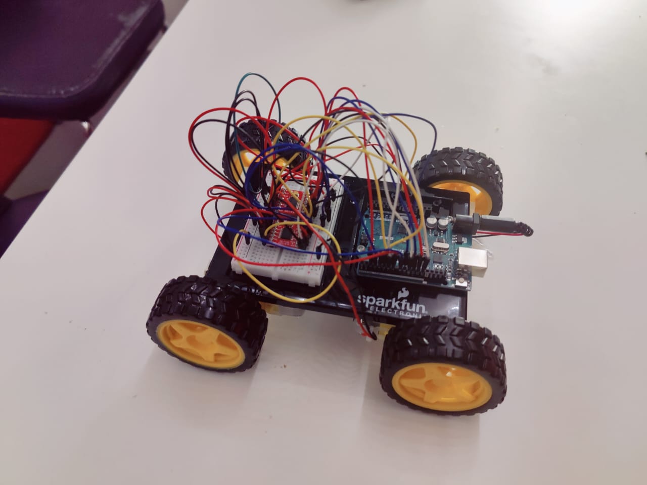
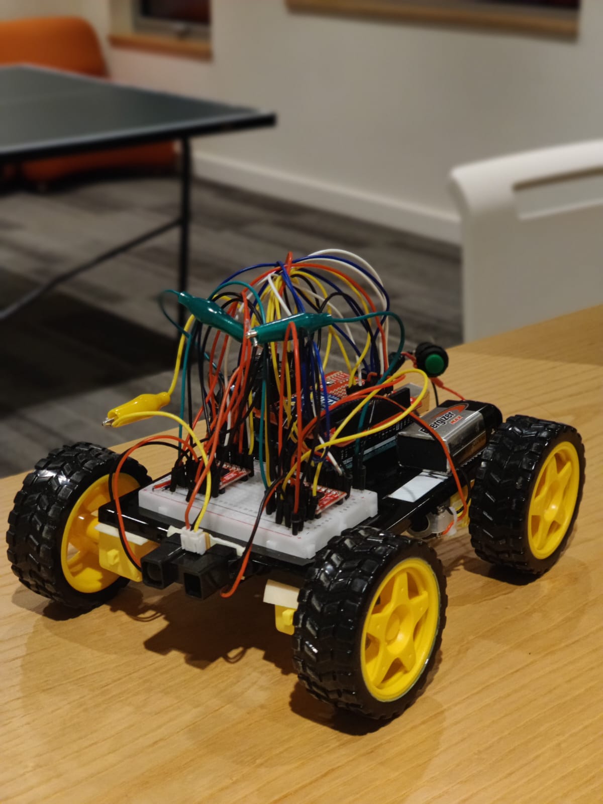
CyberTruck Final Project: Dev & Zaeem

CyberTruck

We built a remotely controlled car which the user was able to control remotely using wireless transmission from P5.js. The user controls the car using arrows keys through p5js and spacebar for braking.


Arduino Components 

  • Arduino Uno (we are going to move it to the MEGA board)
  • Infrared Range Sensor
  • 4 Wheels
  • 4 Motors
  • 2 SparkFun Motor Drivers – Dual TB6612FNG
  • 9V DC Battery
  • Battery Holder
  • XBee Explorer USB 06
  • SparkFun – XBee Shield for Arduino 04
  • XBee 1mW Trace Antenna – Series 1 01
  • XBee 1mW Trace Antenna – Series 1 07
  • 1 On/Off Switch

Implementation

We started by taping the motors using double sided tape and sticking it to the acrylic sheet. Then we connected the wheels to the motor and wired it to the motor driver. We manage to fit all the pins on the Arduino Uno and after couple hours of figuring out the wiring we got both the motor driver on the breadboard. Then came the challenging part of getting the pins defined correctly in the code and using the example code to build up on our car driving code.

We made the car so that it can move in all directions, using two motor drivers and four motors (4 Wheel Drive). This allows the user to control the car’s movement direction using arrow keys on P5.js through Serial Communication with the Arduino connected to the car. In this way, we have the manual driving mode fully working now.

Serial Communication

The p5.js is serially transmitting a direction flag (integer) that is indicating the driving direction and the Arduino is reading this flag and using switch statements to manipulate the motors in order to make the car move in a certain direction. These switch statements control the motors’ speeds and rotation directions.

We decided to manually control the movement of the car – without an IR remote controller – because this is the most functionally important part of this project. We spent the most of our time in the beginning trying to understanding how the motors work and what possibilities there are coding features for motors in Arduino.

The P5js sketch has an instructions page with the driving instructions and port connection instructions. After connecting with USB port the user can start driving the car using the arrow keys allowing the car  to move around and detect and respond to obstacles.

Object Detection

For now, we have implemented object detection in only the forward direction using the IR Range Sensor. Any obstacle detected approximately 40 cm in front of the car causes the car to come to a halt. At this point, the user can only move the car in the backward direction to avoid the obstacle altogether. We spent most of our time working on this functionality in this project – more on this in challenges.

Wireless Transmission

We then moved on to adding wireless transmission using the XBee shield and chip we checked out as per the Professor’s suggestion. One of the XBee chips was connected with P5Js and sent out data from P5. The other chip was connected with the Arduino on the car and received the signals sent out from P5. This transmission also went both ways. Using this scheme, we were able to make our car function fully remotely.

Challenges

Initially, we were using an Ultrasonic Sensor that comes with the Sparkfun Arduino Kit for this purpose. However, there was a long delay time associated with its working and the system was not very response – especially after integrating the XBee chip for wireless transmission later on. This is why we used the more responsive IR Range Sensor and polished the obstacle detection functionality to the point that it works as originally intended.

We also struggled a lot with XCTU and the firmware issue which we couldn’t resolve and thus couldn’t get the XBEE to be configured with each other and setup their PAN IDs. This why despite the handshake functions our wireless communication would break from time to time and the packets would get lost instead of being sent to the car.

Here is the XBees and XCTU Setup Guide that we followed to get the wireless communication established.

Here is the p5js sketch we made:

let dir = 4;
let connect = true;

function preload(){
  title = loadImage("title.png"); 
  mov = loadImage("movement.png");
  brk = loadImage("break.png");
  play = loadImage("play.png");
  arrow = loadImage("arroww.png");
  choose = loadImage("choose.png");
}

function setup() { 
  createCanvas(640, 480);
  textSize(18);
}

function draw() {
  
  background(0);
  fill(255);
  textStyle(BOLD);
  imageMode(CENTER);
  image(title, width/2, height/8, 300, 50);
  image(mov, width/4, height* 3/8, 160, 25);
  image(arrow, width* 3/4, height * 3/8, 100, 65);
  image(brk, width/5, height * 4.5/8, 90, 24);
  fill(0);
  stroke(255);
  strokeWeight(4);
  rectMode(CENTER);
  rect(width* 3/4, height * 4.5/8, 140, 30, 5);  
  
  if (connect) {
    if (!serialActive) {
      image(choose, width/2, height * 6.5/8, 400, 20);
      fill(0);
      rect(width/3 + 10, height*6.5/8, 35, 35, 9);
      fill(255);
      strokeWeight(0);
      textSize(28);
      text("A", width/3 +0.5, height*6.5/8 + 9);
    }
    else {
      text("Connected", 20, 50);
    }
  }
  else {
    rect(width/2, height * 6.5/8, 100, 40, 5);  
    image(play, width/2, height * 6.5/8, 80, 23);
  }

}

function keyPressed() {
  if (key == "a") {
    // important to have in order to start the serial connection!!
    setUpSerial();
  }
  else if (keyCode == UP_ARROW) {
    dir = 0;
  }
  else if (keyCode == LEFT_ARROW) {
    dir = 1;
  }  
  else if (keyCode == RIGHT_ARROW) {  
    dir = 2;
  }  
  else if (keyCode == DOWN_ARROW) {
    dir = 3;
  }
  else if (key == " ") {
    dir = 4;
  }
}

function readSerial(data) {
  ////////////////////////////////////
  //READ FROM ARDUINO HERE
  ////////////////////////////////////
  if (data != null) {
    if (data != "0") {
      let sendToArduino = dir + "\n";
      console.log(sendToArduino)
      writeSerial(sendToArduino);
    } 
    else {
      dir = 4
      let sendToArduino = dir + "\n";
      console.log(sendToArduino)
      writeSerial(sendToArduino);
    }
  }
  //console.log(data);
}


Here is the Arduino code:

#include <SoftwareSerial.h>

SoftwareSerial XBee(2, 3); // RX, TX

//Motor controls
const int ain1Pin = A3; //24 3 45
const int ain2Pin = 4; //26 4
const int pwmAPin = 5; //28 5 2

const int ain1Pin_2 = 13; //37 13
const int ain2Pin_2 = 12; //36 12
const int pwmAPin_2 = 11; //35 11 5

const int bin1Pin = 8; //32 8
const int bin2Pin = 7; //31 7
const int pwmBPin = 6; //30 6 3

const int bin1Pin_2 = 9; //33 9
const int bin2Pin_2 = A2; //22 2 46
const int pwmBPin_2 = 10; //34 10 4


int turbo = 250;
int med = 170;
int slow = 140;
int spd = 0;

int dir = 0; //0 - forward, 1 - right, 2 - left, 3 - reverse, 4 - stop
bool reverse = false;

//ultrasonic sensor pins
//const int ECHO_PIN = A0; //A8 A0
//const int TRIG_PIN = A1; //A9 A1

const int IR = A1;

//the following 2 variables will be used to detect distance with ultrasonic sensor
double time;
double distance;

bool stop = false;
unsigned long timer = 0;

void setup() {

  //setting all motor controls to output
  pinMode(ain1Pin, OUTPUT);
  pinMode(ain2Pin, OUTPUT);
  pinMode(pwmAPin, OUTPUT);

  pinMode(ain1Pin_2, OUTPUT);
  pinMode(ain2Pin_2, OUTPUT);
  pinMode(pwmAPin_2, OUTPUT);

  pinMode(bin1Pin, OUTPUT);
  pinMode(bin2Pin, OUTPUT);
  pinMode(pwmBPin, OUTPUT);

  pinMode(bin1Pin_2, OUTPUT);
  pinMode(bin2Pin_2, OUTPUT);
  pinMode(pwmBPin_2, OUTPUT);


  XBee.begin(9600);
  Serial.begin(9600);

  //  //start the handshake
  while (XBee.available() <= 0) {
    XBee.println(); // send a starting message
    delay(300);
    Serial.println();// wait 1/3 second
  }
}

void loop() {

    Serial.print("xbee available: ");
    Serial.println(XBee.available());

    distance = analogRead(IR);
    delay(2);

    dir = XBee.parseInt();
    spd = 140;

    if (distance <= 600 && distance >= 480) { //stop the car if within range
      if (dir != 3) {
        XBee.write("0");
      }
    } 

    if (XBee.read() == '\n') { //&& !stop ??????
  
     Serial.print("direction: ");
     Serial.println(dir);
      switch (dir) {
        case 0:
          reverse = false;
          analogWrite(pwmAPin, spd);
          analogWrite(pwmAPin_2, spd);
  
          analogWrite(pwmBPin, spd);
          analogWrite(pwmBPin_2, spd);
          
          break;
        case 1:
          analogWrite(pwmAPin, 0);
          analogWrite(pwmAPin_2, spd);
  
          analogWrite(pwmBPin, 0); //set this to 0 to have both wheels off
          analogWrite(pwmBPin_2, spd);
          break;
        case 2:
          analogWrite(pwmAPin, spd); //set this to 0 to have both wheels off
          analogWrite(pwmAPin_2, 0);
  
          analogWrite(pwmBPin, spd);
          analogWrite(pwmBPin_2, 0);
          break;
        case 3:
          reverse = true;
          analogWrite(pwmAPin, spd);
          analogWrite(pwmAPin_2, spd);
  
          analogWrite(pwmBPin, spd);
          analogWrite(pwmBPin_2, spd);
          break;
        case 4: //stop car
          analogWrite(pwmAPin, 0);
          analogWrite(pwmAPin_2, 0);
  
          analogWrite(pwmBPin, 0);
          analogWrite(pwmBPin_2, 0);
          break;
      }
      //      }
      XBee.println();
    }


    if (!reverse) {
  
  
      digitalWrite(ain1Pin, HIGH);
      digitalWrite(ain1Pin_2, HIGH);
  
      digitalWrite(ain2Pin, LOW);
      digitalWrite(ain2Pin_2, LOW);
  
      digitalWrite(bin1Pin, LOW);
      digitalWrite(bin1Pin_2, LOW);
  
      digitalWrite(bin2Pin, HIGH);
      digitalWrite(bin2Pin_2, HIGH);
  
    }
  
    else {
  
      digitalWrite(ain1Pin, LOW);
      digitalWrite(ain1Pin_2, LOW);
  
      digitalWrite(ain2Pin, HIGH);
      digitalWrite(ain2Pin_2, HIGH);
  
      digitalWrite(bin1Pin, HIGH);
      digitalWrite(bin1Pin_2, HIGH);
  
      digitalWrite(bin2Pin, LOW);
      digitalWrite(bin2Pin_2, LOW);
    }
    
  }


P5.Js Sketch

Final Demo Video


Final Project Progress (Dev and Zaeem)

SAGA-GT Car Game

We are building a remotely controlled car that will feature both autopilot mode and manual driving mode. The user will have the choice to decide which mode they want to choose to drive the car.

User-controlled: using arrows keys through p5js, we will make a mini-game in p5js or a real obstacle course if we have time after completion of this mode.
Follow a track or the user: using infrared sensors, we want to make the car move independent of input from the user by following a line on the track.

Arduino Components 

  • Arduino Uno (we are going to move it to the MEGA board)
  • 2 IR Range Sensor
  • 4 Wheels
  • 4 Motors
  • 1 ultrasonic sensor
  • 1 LDR
  • 2 Motor drivers
  • Battery DC
  • Acrylic Sheet
  • Battery Holder

Implementation

We started by taping the motors using double sided tape and sticking it to the acrylic sheet. Then we connected the wheels to the motor and wired it to the motor driver. We manage to fit all the pins on the Arduino Uno and after couple hours of figuring out the wiring we got both the motor driver on the breadboard. Then came the challenging part of getting the pins defined correctly in the code and using the example code to build up on our car driving code.

We made the car so that it can move in all directions, using two motor drivers and four motors (4 Wheel Drive). This allows the user to control the car’s movement direction using arrow keys on P5.js through Serial Communication with the Arduino connected to the car. We have the manual driving mode working now and the car can be controlled manually from the p5.js interface with the arrow keys.

The p5.js is serially transmitting a direction flag (integer) that is indicating the driving direction and the Arduino is reading this flag and using switch statements to make the car move. These switch statements control the motors’ speeds and rotation directions.

We decided to manually control the movement of the car – without the IR controller – because this is the most functionally important part of this project. We spent the weekend understanding how the motors work and what possibilities there are coding features for motors in Arduino. We are now confident enough in our basic understanding of motors to start finalizing the project.

Here is a video of the car driving:

Manual car driving Demo


Here is the p5js sketch we made:

let dir = 0;
let direction = 0;

function setup() {
  createCanvas(640, 480);
  
  textSize(18);
}

function draw() {

  if (!serialActive) {
    text("Press Space Bar to select Serial Port", 20, 30);
  } else {
    text("Connected", 20, 70);
  }
  switch(direction) {
  case 0:
    dir = 0;
    break;
  case 1:
    dir = 1;
    break;
  case 2:
    dir = 2;
    break;
  case 3:
    dir = 3;
    break;
  default:
    // code block
  }
  
  print(dir);
}

function keyPressed() {
  if (key == " ") {
    // important to have in order to start the serial connection!!
    setUpSerial();
  }
  else if (keyCode == UP_ARROW) {
    direction = 0;
  }
  else if (keyCode == LEFT_ARROW) {
    direction = 1;
  }  
  else if (keyCode == RIGHT_ARROW) {
    direction = 2;
  }  
  else if (keyCode == DOWN_ARROW) {
    direction = 3;
  }
}

function readSerial(data) {
  ////////////////////////////////////
  //READ FROM ARDUINO HERE
  ////////////////////////////////////

  if (data != null) {
    //////////////////////////////////
    //SEND TO ARDUINO HERE (handshake)
    //////////////////////////////////
    let sendToArduino = dir + "\n";
    console.log(sendToArduino)
    writeSerial(sendToArduino);
  }
}


Here is the Arduino code:

//Motor controls
const int ain1Pin = 3;
const int ain2Pin = 4;
const int pwmAPin = 5;

const int ain1Pin_2 = 13;
const int ain2Pin_2 = 12;
const int pwmAPin_2 = 11;

const int bin1Pin = 8;
const int bin2Pin = 7;
const int pwmBPin = 6;

const int bin1Pin_2 = 9;
const int bin2Pin_2 = 2;
const int pwmBPin_2 = 10;

int dir = 0; //0 - forward, 1 - right, 2 - left, 3 - reverse
bool reverse = false;

void setup() {

  //setting all motor controls to output
  pinMode(ain1Pin, OUTPUT);
  pinMode(ain2Pin, OUTPUT);
  pinMode(pwmAPin, OUTPUT); 

  pinMode(ain1Pin_2, OUTPUT);
  pinMode(ain2Pin_2, OUTPUT);
  pinMode(pwmAPin_2, OUTPUT); 

  pinMode(bin1Pin, OUTPUT);
  pinMode(bin2Pin, OUTPUT);
  pinMode(pwmBPin, OUTPUT);

  pinMode(bin1Pin_2, OUTPUT);
  pinMode(bin2Pin_2, OUTPUT);
  pinMode(pwmBPin_2, OUTPUT);

  Serial.begin(9600);

  // start the handshake
  while (Serial.available() <= 0) {
    Serial.println("0,0"); // send a starting message
    delay(300);            // wait 1/3 second
  }
}

void loop() {

  while (Serial.available()) {

      if (!reverse){
          digitalWrite(ain1Pin, LOW);
          digitalWrite(ain1Pin_2,HIGH);
        
          digitalWrite(ain2Pin, HIGH);
          digitalWrite(ain2Pin_2,LOW);
        
          digitalWrite(bin1Pin, HIGH);
          digitalWrite(bin1Pin_2,LOW);
        
          digitalWrite(bin2Pin,LOW);
          digitalWrite(bin2Pin_2,HIGH);
      }

      else {
          digitalWrite(ain1Pin, HIGH);
          digitalWrite(ain1Pin_2,LOW);
        
          digitalWrite(ain2Pin, LOW);
          digitalWrite(ain2Pin_2,HIGH);
        
          digitalWrite(bin1Pin, LOW);
          digitalWrite(bin1Pin_2,HIGH);
        
          digitalWrite(bin2Pin,HIGH);
          digitalWrite(bin2Pin_2,LOW);
      }
    
      
      dir = Serial.parseInt();

      //completing the "handshake"!!!!!!!!!!!!!!!!!!!!!
      Serial.println(dir);
       
      if (Serial.read() == '\n') {
          switch(dir) {
          case 0:  
            reverse = false;
            analogWrite(pwmAPin, 255);
            analogWrite(pwmAPin_2, 255);
          
            analogWrite(pwmBPin, 255);
            analogWrite(pwmBPin_2,255);
            break;
          case 1:
            analogWrite(pwmAPin, 255);
            analogWrite(pwmAPin_2, 0);
          
            analogWrite(pwmBPin, 255);
            analogWrite(pwmBPin_2,255);
            break;
          case 2:
            analogWrite(pwmAPin, 255);
            analogWrite(pwmAPin_2, 255);
          
            analogWrite(pwmBPin, 255);
            analogWrite(pwmBPin_2, 0);
            break;
          case 3:
            reverse = true;
            analogWrite(pwmAPin, 255);
            analogWrite(pwmAPin_2, 255);
          
            analogWrite(pwmBPin, 255);
            analogWrite(pwmBPin_2,255);
            break;
          }
      }
  }

  //GO THROUGH THE KEYPRESSED IN DRAW LOOP OF P5JS

}

Plans

At first, the P5js sketch will have an initial menu screen with the two modes for the user to choose from. If the user chooses the autopilot mode, the car will be able to move around and avoid obstacles (obstacle detections) and also be able to drive automatically on a predefined course/ path (by following a black tape on the course using IR sensors). We plan to build a driving course to accompany our car for this project. The user use this course for “test-drives”.

We plan to add wireless transmission using the XBEE shield and chip we checked out as per the Professor’s suggestion. The Arduino connected  with the computer will be in Serial Communication with p5js and will send out signals to the Arduino connected with the car to maintain the p5js to car communication. We also plan on adding motion sensors to the car to gauge braking distance – we will add a simply braking functionality too.

In summary:
  • Add wireless Transmission feature
  • Line follower (Auto driving feature): Add 2 infrared sensors
  • Glue the motors to the board and and align the wheels properly
  • Screw the Arduino firmly to the board
  • Create the driving course
  • Work on the P5.js interface


Serial Communication Exercise

Exercise 1

Was to make the ellipse in p5.js move on the horizontal axis, in the middle of the screen, and nothing on Arduino was controlled by p5.js.

P5.js Code
let serial; // variable to hold an instance of the serialport library
let portName = "/dev/cu.usbmodem101"; // fill in your serial port name here
let xPos=0;
let yPos=0;
let onOff=0;

function setup() {
  createCanvas(640, 480);
  serial = new p5.SerialPort(); // make a new instance of the serialport library
  serial.on("list", printList); // set a callback function for the serialport list event
  serial.on("connected", serverConnected); // callback for connecting to the server
  serial.on("open", portOpen); // callback for the port opening
  serial.on("data", serialEvent); // callback for when new data arrives
  serial.on("error", serialError); // callback for errors
  serial.on("close", portClose); // callback for the port closing

  serial.list(); // list the serial ports
  serial.open(portName); // open a serial port
}

function draw() {
  background(255);
  ellipse(xPos, height/2, 50, 50); // draw the circle
}

// get the list of ports:
function printList(portList) {
  // portList is an array of serial port names
  for (let i = 0; i < portList.length; i++) {
    // Display the list the console:
    print(i + " " + portList[i]);
  }
}

function serverConnected() {
  print("connected to server.");
}

function portOpen() {
  print("the serial port opened.");
}

function serialEvent() {
  // read a string from the serial port
  // until you get carriage return and newline:
  let inString = serial.readLine();
 
  //check to see that there's actually a string there:
  if (inString.length > 0) {
    xPos = map(inString, 0, 1023, 0, width);
  }

  serial.write(onOff);
}

function serialError(err) {
  print("Something went wrong with the serial port. " + err);
}

function portClose() {
  print("The serial port closed.");
}
Arduino Code
void setup() {
  Serial.begin(9600);
  pinMode(5, OUTPUT);
  while (Serial.available() <= 0) {
    Serial.println("0,0"); // send a starting message
    delay(300);              // wait 1/3 second
  }
}

void loop() {
  while (Serial.available() > 0) {
    // read the incoming byte:
   int inByte = Serial.read();
   analogWrite(5, inByte);

    int sensorValue = analogRead(A0);
    Serial.print(sensorValue);
    Serial.println();
  }
}

Exercise 2

In this exercise, we had to make something that controls the LED brightness from p5.js
P5.js Code
let serial; // variable to hold an instance of the serialport library
let portName = "/dev/cu.usbmodem101"; // fill in your serial port name here
let xPos=0;
let yPos=0;
let onOff=0;
let brness = 50;
let circlePos;
let counter = 0;

function setup() {
  createCanvas(640, 480);
  serial = new p5.SerialPort(); // make a new instance of the serialport library
  serial.on("list", printList); // set a callback function for the serialport list event
  serial.on("connected", serverConnected); // callback for connecting to the server
  serial.on("open", portOpen); // callback for the port opening
  serial.on("data", serialEvent); // callback for when new data arrives
  serial.on("error", serialError); // callback for errors
  serial.on("close", portClose); // callback for the port closing

  serial.list(); // list the serial ports
  serial.open(portName); // open a serial port
  circlePos = width/6;
}

function draw() {
  background(255);
  fill(brness*counter, brness*counter, brness*counter);
  ellipse(circlePos*(counter+1) - 50, height/2, 50, 50); 
}

function keyPressed() {
  if (keyCode === LEFT_ARROW) {
    if (counter > 0) {
      counter--;
    }
    else{
      counter = 0;
    }
  } else if (keyCode === RIGHT_ARROW) {
    if (counter < 5) {
      counter++;
    }
    else{
      counter = 5;
    }
  }
  
  serial.write(counter);
}

// get the list of ports:
function printList(portList) {
  // portList is an array of serial port names
  for (let i = 0; i < portList.length; i++) {
    // Display the list the console:
    print(i + " " + portList[i]);
  }
}

function serverConnected() {
  print("connected to server.");
}

function portOpen() {
  print("the serial port opened.");
}

function serialEvent() {
  // read a string from the serial port
  // until you get carriage return and newline:
  let inString = serial.readLine();
 
  //check to see that there's actually a string there:
  if (inString.length > 0) {
    xPos = map(inString, 0, 1023, 0, width);
  }

  serial.write(onOff);
}

function serialError(err) {
  print("Something went wrong with the serial port. " + err);
}

function portClose() {
  print("The serial port closed.");
}
Arduino Code
void setup() {
  Serial.begin(9600);
  pinMode(5, OUTPUT);
  while (Serial.available() <= 0) {
    Serial.println("0,0"); // send a starting message
    delay(300);              // wait 1/3 second
  }
}

void loop() {
  while (Serial.available() > 0) {
    // read the incoming byte:
   int inByte = Serial.read();
   int brightness = inByte * 50;
   analogWrite(5, brightness);
  }
}
Demo
Exercise 3
For this last exercise, we had to use the gravity wind example and make it so every time the ball bounces one led lights up and then turns off, and we can control the wind from one of the analog sensors.
P5.js Code
let velocity;
let gravity;
let position;
let acceleration;
let wind;
let drag = 0.99;
let mass = 50;
let hDampening;

let serial; // variable to hold an instance of the serialport library
let portName = "/dev/cu.usbmodem101"; // fill in your serial port name here
let xPos=0;
let yPos=0;
let onOff=0;

function setup() {
  createCanvas(640, 360);
  serial = new p5.SerialPort(); // make a new instance of the serialport library
  serial.on("list", printList); // set a callback function for the serialport list event
  serial.on("connected", serverConnected); // callback for connecting to the server
  serial.on("open", portOpen); // callback for the port opening
  serial.on("data", serialEvent); // callback for when new data arrives
  serial.on("error", serialError); // callback for errors
  serial.on("close", portClose); // callback for the port closing

  serial.list(); // list the serial ports
  serial.open(portName); // open a serial port
  
  //initial setup
  noFill();
  position = createVector(width/2, 0);
  velocity = createVector(0,0);
  acceleration = createVector(0,0);
  gravity = createVector(0, 0.5*mass);
  wind = createVector(0,0);
  hDampening=map(mass,15,80,.98,.96);
}

function draw() {
  background(0);
  if (!keyPressed){
    
    //wind.x= 0;
    console.log(xPos);
    velocity.x*=hDampening;
  }
  
  wind.x = map(xPos, 0, width, -1, 1);
  
  // if (xPos < width/2) {
  //     wind.x = -1;
  //   }
  // else {
  //     wind.x = 1;
  //   }
  applyForce(wind);
  applyForce(gravity);
  velocity.add(acceleration);
  velocity.mult(drag);
  position.add(velocity);
  acceleration.mult(0);
  fill(255);
  ellipse(position.x,position.y,mass,mass);
  
//   if (position.y > height-mass*(2/3)) {
      
//   }
  
  if (position.y > height-mass/2 - 40) {
    if (velocity.y > 1) {
      serial.write(255);
    }
    
    if (position.y > height-mass/2) {
      velocity.y *= -0.9;  // A little dampening when hitting the bottom
      position.y = height-mass/2;
    }
  }
}

function applyForce(force){
  // Newton's 2nd law: F = M * A
  // or A = F / M
  let f = p5.Vector.div(force, mass);
  acceleration.add(f);
}

function keyPressed(){
  if (keyCode==LEFT_ARROW){
    wind.x=-1;
  }
  if (keyCode==RIGHT_ARROW){
    wind.x=1;
  }
  if (key==' '){
    mass=random(15,80);
    position.y=-mass;
    velocity.mult(0);
  }
}

// get the list of ports:
function printList(portList) {
  // portList is an array of serial port names
  for (let i = 0; i < portList.length; i++) {
    // Display the list the console:
    print(i + " " + portList[i]);
  }
}

function serverConnected() {
  print("connected to server.");
}

function portOpen() {
  print("the serial port opened.");
}

function serialEvent() {
  // read a string from the serial port
  // until you get carriage return and newline:
  let inString = serial.readLine();
  //xPos = map(inString, 0, 1023, 0, width);
 
  //check to see that there's actually a string there:
  if (inString.length > 0) {
    xPos = map(inString, 0, 1023, 0, width);
  }

  serial.write(onOff);
}

function serialError(err) {
  print("Something went wrong with the serial port. " + err);
}

function portClose() {
  print("The serial port closed.");
}
Arduino Code
void setup() {
  Serial.begin(9600);
  pinMode(5, OUTPUT);
  while (Serial.available() <= 0) {
    Serial.println("0,0"); // send a starting message
    delay(300);              // wait 1/3 second
  }
}

void loop() {
  while (Serial.available() > 0) {
    // read the incoming byte:
   int inByte = Serial.read();
   analogWrite(5, inByte);

    int sensorValue = analogRead(A0);
    Serial.print(sensorValue);
    Serial.println();
  }
}
Demo


Dev: Final project proposal

Ideation 

For the final project, I want to build a car that will feature both autopilot mode and manual driving mode. The user will have the choice to decide which mode they want to choose to drive the car.

If the user chooses the autopilot mode, the car will be able to move around and avoid all obstacles with (obstacle detections) and also be able to drive automatically on a predefined course/ path. Whereas for the manual mode, the user will be able to control the car through p5.js using the arrows. (perhaps connect it to a controller)

I also plan to build a driving course that the user can drive in and test the autopilot mode. I’m planning to have a line following feature where the car will follow the line on the road. (Even make decisions where possible, Maybe that is too complicated?)

P5.js

The p5.js will show a window with its instructions and feature for the 2 modes (autopilot mode and manual mode) allowing the user to choose their option. The arrows will allow the user to control the car’s movement and drive the car around the course

Arduino Components needed:

  • 2 IR Range Sensors
  • 4 wheels
  • 1 ultrasonic sensor
  • 1 Servo
  • 1 LDR
  • L298N motor driver 
  • Battery DC
  • few LEDs

Piezo Piano (Dev & Zaeem)

Inspiration

For this assignment, using both analog and digital sensors, we were tasked to create a musical instrument. At first, we thought of creating a drum set. After doing some research we realized that we will have to connect a MIDI tool and use that as an interface in order to make a drum that mimics the actual sounds that come from a drum. Since we had already covered some notes in class (pitches), we decided to make a Piano instead but using the same methods we would use to make the drums.

Implementation

We started by researching all our possible analog sensors. We think the sensor best-suited for this task is a piezoelectric pressure sensor because we wanted to measure the force with which the user presses down on each key.

Next, we wanted to design our piano. For this, we used a cardboard box from the lab which had a piece of cardboard that could be flipped up and down. This flipping part would serve as the piano keys and the rest of the box can be used to hide the Arduino and the circuits. Piezo sensors are stuck underneath each key using double-sided tape. We also soldered wires together to make the circuit compact enough to fit inside the cardboard box and so that the wires may be led to the Arduino through holes in the box. Finally, we used a potentiometer to adjust for the volume of the buzzer.

Initial setup (testing)

Reflection

While we have made a piano that can play 6 notes, it’s biggest drawback is in how limited it is. We believe that this problem can be solved by either having a button (switch) that changes all the notes being played so that every key is now bound to a new note when the button is pressed or by achieving the same thing using a potentiometer.

We ran into a problem at the end. The last piezo sensor does not seem to work. We spent most of our time trying to figure out what’s wrong with our code that triggers the last sensor every time in draw loop. But, in the end, we figured that the sensor was faulty. Since we did not have enough time to fix this and use another sensor (we had already soldered the faulty one), we did not include that sensor in the piano.

Here is how the final setup looked. Of course, this was not how we imagined it to be, but it was the right thing to do since we didn’t want to break the connections and have the wires come loose. Even after all the soldering we did, there were few wires that did not connect properly to the alligator cables and thus the piezo disk would play any sound.

Arduino Code

#include "pitches.h"

int analogpin[6] = {A0, A1, A2, A3, A4, A5};
const int buzpin = 4;
int threshold = 200;
int flag = 0; 
bool a5 = false;

double curr;
double goal;

void setup()
{
  Serial.begin(9600);
  pinMode(buzpin, OUTPUT);
}

void loop()
{
//  int test = analogRead(analogpin[4]);
//  Serial.println(test);

  if (analogRead(analogpin[0]) < threshold && flag == 0) //&& flag == 0
  {
    flag = 1;
    Serial.println("A0");
    curr = millis();
    while(millis() < curr + 100){
      tone(buzpin, NOTE_B4, 100); //need the duration here?
    }
  }

  if (analogRead(analogpin[1]) < threshold && flag == 0) //&& flag == 0
  {
    flag = 1;
    Serial.println("A1, pressing");
    digitalWrite(buzpin, HIGH);
    curr = millis();
    while(millis() < curr + 100){
      tone(buzpin, NOTE_D4, 100); //need the duration here?
    }
  }
  
  if (analogRead(analogpin[2]) < threshold && flag == 0) //&& flag == 0
  {
    flag = 1;
    Serial.println("A2");
    curr = millis();
    while(millis() < curr + 100){
      tone(buzpin, NOTE_C4, 100); //need the duration here?
    }
  }
  
  if (analogRead(analogpin[3]) < threshold && flag == 0) //&& flag == 0
  {
    flag = 1;
    Serial.println("A3");
    curr = millis();
    while(millis() < curr + 100){
      tone(buzpin, NOTE_G4, 100); //need the duration here?
    }
  }

  
  if (analogRead(analogpin[4]) < threshold && flag == 0) //&& flag == 0
  {
    flag = 1;
    Serial.println("A4");
    curr = millis();
    while(millis() < curr + 100){
      tone(buzpin, NOTE_G3, 100); //need the duration here?
    }
  }
   
  if (analogRead(analogpin[5]) < threshold && flag == 0 && a5 == false) //
  {
    flag = 1;
    a5 = true;
    Serial.println("A5");
    curr = millis();
    while(millis() < curr + 100){
      tone(buzpin, NOTE_D3, 100); //need the duration here?
      a5 = false;
    }
  }

  flag = 0; 
}


Dev: Night Flower

Inspiration

Pictures: Flowers Glow Under UV-Induced Visible Fluorescence

Source: Read more in this article 

For this weeks assignment I drew inspiration from this kind of night glowing flowers that only bloom up at night in the absence of sunlight/UV light. I wanted to create something similar with LED and the photo sensor in order to glow up the flower in the absence of light. In order to do this I had to use a photosensor add mad the brightness on to the range of values between 0 and 255.

This also allowed me to control the brightness level as the intensity of light changed. As shown in the video below I wanted to mimic a sunrise and sunset effect where the flower would brighten up as the environment becomes darker.

Implementation

I started by hooking up a LED and a push down button with the basic on off implementation. On top of this I used a photosensor in a 10k resistor for the connection on the circuit. The LED and button served as digital input to read data into the program while the photo center served as analog input for this project. In order to control the light I thought of doing something different than the traditional HIGH and LOW method. I thought of implementing it by varrying its light value depending on the brightness level. This was done by using analogWrite by sending the mapped light value to the LED pin.

As shown in the code below I tried to play around with the values in order to map it in a way that allowed the brightness to smoothly transition and show the dimming and fading feature. (Although this is was very satisfying for me unfortunately the camera on my phone was not able to capture the dimming effect).

Demo Video

Arduino Code

int led = 3; // LED pin 
int ldr = A0; // LDR pin
int button = 5; // Button pin
bool on = false; // Boolean variable for the state of the LED 

void setup() {
  Serial.begin(9600);
  pinMode(led, OUTPUT); // Set the LED pinmode
  pinMode(ldr, INPUT); // Set the LDR pinmode
  pinMode(button, INPUT); // Set the button pinmode
}
void loop() {
  
// read the brightness from the ldr
  int brightness = analogRead(ldr);
// check if switch is clicked
  if (on == false && digitalRead(button)== HIGH){
    on = true; // Setting on to be true
  }
  if (on == true && digitalRead(button) == HIGH){
    on = false;  // Setting on to be false
  }

   int mappedLightValue = map(brightness, 60, 700, 255, 0); // nothing the brightness onto the range 0 to 255 but in reverse order
  // if switch is clicked, then proceed 
  if (on==true){ // if the on state is true
    if (brightness < 370) { // 
      analogWrite(led, mappedLightValue); // writing the lights value to the LED pin
//      Serial.println(mappedLightValue); // call printing out the mapped light value for checking
    }
    else {
      digitalWrite(led, LOW); // turning the light off if it's too bright
    }
  }
  else if (on==false) {digitalWrite(led, LOW);}  // Setting the on state to be false otherwise
}


Unusual Switch: Car braking

For this week’s unusual switch assignment that we had to implement a simple circuit switch without the use of our hands, I used a real life example as my inspiration for this weeks exercise. Commonly found in cars and other vehicles was the brake light at the back of the cars which lights up every time you press down the brake pedal. 

Car Backlight Pictures | Download Free Images on Unsplash

I started by making a simple circuit which would light up the LED every time the circuit was closed. Then I used two more cables to cut the supply to the LED row on the breadboard and also disconnected the ground to the main + and –  bus on the breadboard. Then I used two wires to redirect the connection onto a sheet of paper and tape the ends of wire flat down onto the paper. In order to close the circuit and make the switch functional I came up with the idea of using aluminum foil which act behave as the conductor of electricity. By attached the piece of aluminum foil to the bottom of my shoe I was able to close the circuit. Through this manner I was able to light up the bulb every time I press down onto the sheet of paper mimicking the braking functionality in a car.


Midterm Game: Soceroo

Idea and Inspiration

The idea I had for my game for this midterm assignment was the classic breakout game. From a young age I had played this game and I really wanted to code this game out and re-create my childhood experience. As simple as this game looks, this 2D game isn’t as easy as it appears to be. I wanted to speed up the game and decreased the paddle width as the user loses its lives.

Game Implementation 

I want to start by coding how the game would work and by coding out the main object in the game which is the ball, bricks, paddle. After any shading all my global variables I created a bricks array which would hold each brick as an instance just like the object oriented assignment. I also populated and array with the brick colors in order to create a fading effect by using colors close to one another. I then created a function for paddle which was responsible for moving its position left and right depending on the key pressed which would raise a Boolean flag that triggered the movement. 

Then I went on to create the ball which was essentially a circle but this was the most time consuming function. After carefully figuring out the math I was able to get the moving and bouncing effect. I used several if conditions to restrict the circles X and Y coordinate in between the canvas and the interaction with the paddle. The hardest part of all this was the collision detection. For this, I created a different function which checked for the collision at the bottom of the brick by looking at the coordinate range where the ball’s radius would overlap with the bricks dimension which would mean there was a collision and it will return true.

In order to make the brick disappear after the collision I iterated through the bricks array and checked for collision between the ball and the particle brick and if so I used the splice() function in p5.js to remove the brick from the array. I would also increment the score at this point. For the loss of life it was fairly easy since I would just check if the circles y-coordinate was greater than the height of the canvas which meant that the player had failed you make contact with the paddle and has lost a life. 

For creating the bricks on the board are used functions in a way that allowed the bricks to be populated across the canvas using nested for loops. The growing of brick would just fill each brick with its corresponding color and simply create a rectangle with respected coordinates.

Furthermore, for the paddle I wanted to make it as realistic as possible. Of course there wasn’t much physics but i used a simply inverted the x direction when the ball hit the paddle. In order to get this to work correctly, I tried several different approaches like reflecting the angle if it hit ton either half of the paddle but it didn’t work logically and kept bouncing on the same side. So i resorted to using the negative and positive direction (+dx/-dx) for the switching the side and bouncing it to its respective opposite side. However, an additional effect that I implemented was the ball bouncing off the edge of the paddle to the same side.

I tried to increase the difficulty for the user by slowing increasing the speed of the ball as the game progressed and to make it more challenging the player had to move the paddle faster, which also decreased in width as the score went up. I also added sound when the user got a point (which was one brick was destroyed). Sound effects were also played when the user lost a life, game was over or won the game.


Midterm game progress

 Idea and Inspiration

The idea I had for my game for this midterm assignment was the classic breakout game. From a young age I had played this game and I really wanted to code this game out and re-create my childhood experience. As simple as this game looks, this 2D game isn’t as easy as it appears to be. I wish to create different levels for this game and plan to decrease the paddle width as the user loses its lives. The progress I have made so far is purely on the coding and logic of the game itself and not the appearance or functionality in terms of importing sprites for the paddle and having sound effects along with the menu screen.

Game Implementation 

I want to start by coding how the game would work and by coding out the main object in the game which is the ball, bricks, paddle. After any shading all my global variables I created a bricks array which would hold each brick as an instance just like the object oriented assignment. I also populated and array with the brick colors in order to create a fading effect by using colors close to one another. I then created a function for paddle which was responsible for moving its position left and right depending on the key pressed which would raise a Boolean flag that triggered the movement. 

Then I went on to create the ball which was essentially a circle but this was the most time consuming function. After carefully figuring out the math I was able to get the moving and bouncing effect. I used several if conditions to restrict the circles X and Y coordinate in between the canvas and the interaction with the paddle. The hardest part of all this was the collision detection. For this, I created a different function which checked for the collision at the bottom of the brick by looking at the coordinate range where the ball’s radius would overlap with the bricks dimension which would mean there was a collision and it will return true. In order to make the brick disappear after the collision I iterated through the bricks array and checked for collision between the ball and the particle brick and if so I used the splice() function in p5.js to remove the brick from the array. I would also increment the score at this point. For the loss of life it was fairly easy since I would just check if the circles y-coordinate was greater than the height of the canvas which meant that the player had failed you make contact with the paddle and has lost a life. 

For creating the bricks on the board are used functions in a way that allowed the bricks to be populated across the canvas using nested for loops. The growing of brick would just fill each brick with its corresponding color and simply create a rectangle with respected coordinates. I am intending to replace this rectangle with a Sprite later on but as of now I wanted to see if I was able to use this to get the game up and working.

I also created messages for the user when life is lost or restart game but I have not been able to add any buttons yet. I wish to create a whole menu screen which would be used before start of game and restart along with different levels and possibly even multiplayer option.

Plan

I plan to add the following things to my game:

  • Create gradient background which would change as the user score increases
  • Add sound effects when there is a collision and a brick is destroyed
  • Increase the game difficulty by reducing the paddle size making it harder and harder.
  • Import sprites for the battle and possibly other enemies/obstacles that the Player might have to avoid.
  • Create a menu screen with instructions at the start of the game and restart.
  • Add multiplayer option which would’ve allowed two players to compete against one another. However I feel like this would be time consuming and difficult to implement as it might require a complete new code.


Assignment 4: Flights Data Visualization

For this assignment I wanted to use data visualization and how I could use simple data to create an artwork or something interactive. After watching few videos and searching for possible data that I could use I came across this Visual Data Analysis lab that had used this flights dataset to create a data visualization.

After looking at this i was inspired to use the same dataset but to create an interactive world map using this dataset which could allow the user to enter a country as input and the sketch would show all the destinations they flights have gone to and what the number of flights are.

Initially, the downloaded flights.csv file was more than 5mb and P5.js did not allow me to upload the file. Hence I filtered the data as per the things I would need for this assignment. Since I was focusing on countries alone I removed the airport names along with the cities the flights were coming and going to.

For loading the data into my sketch i used the loadTable() function in P5.js that allowed me to read the data from my file and store it into my table.

After loading the table I set up a function call process where each line of the data would be fed in as a row. Then I’m using a get info function which gets the longitude and latitude from the row of the departure and destination location. It also maps out the longitude and latitude coordinates onto the dimensions of the sketch which is later used to draw circles at each location. This initial mapping and drawing of ellipses allows the green dots to create a rough outline of the world map onto the sketch. 

Then I’m using a get flights detail function that matches the input from the user to the row data and to avoid case sensitivity issues a converted both strings to uppercase and check if they are the same.  If so, and I am using the row’s departure and destination mapped coordinates to draw a line between them by pushing and popping each one. I’m also using a flight counter variable which allows me to keep track of the number of flights and displayed to the user as output.

Click here to view the sketch in fullscreen mode.