Concept of the Game
The aim of this Final Project is to build an interactive multimedia system that involves physical interaction and relies on a multimedia computer for processing or data analysis. To create a Mini Basketball Arcade Machine, I am using BOTH P5 AND Arduino. The mini Basketball Arcade Machine will be a tabletop-sized arcade game that will allow users to play basketball by shooting miniature basketballs into a hoop. Whenever the ball successfully passes through the hoop, it makes contact with the flex sensor causing alterations in its readings. As soon as a modification is identified in the flex sensor’s values, the player is credited with certain amount of points. Failing to score does not lead to a decrease in points. The game has a time limit, and when the time is up, a buzzer goes off to signify the end of the game. Players can see their score and the highest score achieved and can choose to play again. The machine utilizes Arduino to detect when the player shoots the basketball and p5.js to present the score and time on the scoreboard.
Implementation
INTERACTION DESIGN
The interaction design of the Mini Basketball Arcade Game is centered around the physical act of shooting a miniature basketball into the hoop, which is the primary user input. The flex sensor provides an accurate and responsive way to detect when the ball passes through the hoop, and the Arduino board processes this data and communicates it to the P5.js program. This allows the user to receive immediate feedback on their performance in the form of an updated score on the computer screen.
The P5.js program provides a visually appealing and intuitive interface for the user, with a scoreboard that displays the current score and time remaining in the game. The program also displays the basketball hoop and basketballs for the user to shoot, creating a realistic and immersive experience. When the user successfully shoots the ball through the hoop, the program responds with a satisfying feedback sound and updates the score accordingly.
The time limit of the game adds an additional layer of challenge and excitement to the interaction design, encouraging the user to stay engaged and focused. When the time runs out, a buzzer sounds, signaling the end of the game and allowing the user to view their final score and compare it to the highest score achieved.
Overall, the Mini Basketball Arcade Game is a well-designed and engaging interactive system that combines hardware and software to create a realistic and immersive basketball arcade experience.
P5.JS CODE
The code starts by defining the necessary variables and objects such as the background music, spritesheets, and sounds. The program also sets up the serial connection to the Arduino. The “preload()” function is used to load all the necessary assets such as the images and sounds. The “setup()” function initializes the canvas and sets up the game by creating instances of the “Game” class, loading the spritesheets and setting the font. The “draw()” function is used to draw all the different screens of the game, and it also determines which screen to display based on the game’s state.
// Set up the canvas with width and height of 600 pixels
function setup() {
  createCanvas(600, 600);

  // Set the text size to 18 pixels
  textSize(18);

  // Set up the serial port for communication with external devices
  setUpSerial();

  // Create a new instance of the Game class
  game = new Game();

  // Set text alignment to center
  textAlign(CENTER);

  // Set rectangle mode to center
  rectMode(CENTER);

  // Resize the spritesheet to half its original size
  spritesheet.resize(spritesheet.width / 2, spritesheet.height / 2);

  // Set the width and height of the individual basketball sprite
  w = spritesheet.width / 6;
  h = spritesheet.height;

  // Create an array of basketball sprites by extracting them from the spritesheet
  for (let i = 0; i < 6; i++) {
    bballSprite[i] = spritesheet.get(i * w, 0, w, h);
  }

  // Set the font to be used for text rendering
  textFont(font);
}
function draw() {
  // If the serial port is not active
  if (!serialActive) {
    fill(255);
    text("Press Space Bar to select Serial Port", 20, 30);
  }
  // If the serial port is active
  else {
    background(255);
    // If the game state is 0, call the click function
    if (game.state == 0) {
      game.click();
    }
    // If the game state is 1, call the menu function
    else if (game.state == 1) {
      game.menu();
    }
    // If the game state is 2, call the countdown function
    else if (game.state == 2) {
      game.countdown();
    }
    // If the game state is 3, call the game function
    else if (game.state == 3) {
      game.game();
    }
    // If the game state is 4, call the endScreen function
    else if (game.state == 4) {
      game.endScreen();
    }
  }
}
The game is a basketball shooting game where the objective is to score as many points as possible within the time limit of 45 seconds. The game is broken down into different states based on the stage of the game. The game has a starting screen, a menu, a countdown screen, the actual game screen, and the end screen. The program also uses sounds to add to the user experience. The program uses the p5.web-serial.js library to interact with the Arduino to receive data.
The game logic is handled by the “Game” class. The class constructor initializes the state of the game, and it has methods to handle each state of the game. The “click()” method displays a starting screen with instructions, and the “menu()” method displays the menu where the user can start the game. The “countdown()” method handles the countdown before the game starts. The “game()” method handles the actual game where the user interacts with the Arduino to shoot the basketball. The “endScreen()” method handles the display of the final score and provides an option to restart the game.
class Game {
  constructor() {
    // Initializes game state, score, time, and high score
    this.state = 0;
    this.score = 0;
    this.highScore = 0;
    this.time = 45;
  }

  click() {
    // Displays start message on click
    push();
    background(255,159,159);
    fill(0);
    textSize(width / 10);
    text("Click to start", width / 2, height / 2);
    pop();
  }

  menu() {
    // Animates the basketball sprite and displays the menu
    if (frameCount % 5 == 0) {
      step++;
      if (step == 6) {
        x += w;
        step = 0;
      }
      if (x >= width) {
        x = 0;
      }
    }
    push();
    imageMode(CORNER);
    image(menu, 0, 0, width, height);
    pop();
    push();
    // Displays the basketball sprite, fade animation, and start button
    image(bballSprite[step], x, (2 * height) / 3);
    if (fade < 255) {
      fade += 2;
    }
    fill(0, 150);
    rect(width / 2, (4.9 * height) / 9, width / 4, height / 7, 20);
    fill(178, fade);
    textSize(width / 10);
    textFont(font);
    text("Start", width / 2, (3 * height) / 5);
    pop();
  }

  countdown() {
    // Displays countdown before starting the game
    push();
    background(0);
    fill(255);
    textSize(width / 12);
    text(cd, width / 2, height / 2);
    if ((frameCount - startTime) % 45 == 0) {
      cd--;
    }
    if (cd == 0) {
      // Plays crowd sound and updates game state when countdown is over
      crowdSound.setVolume(0.5);
      crowdSound.loop();
      this.state++;
      startTime = frameCount;
    }
    pop();
  }

  game() {
    push();
    // Displays game background and score/time counters
    imageMode(CORNER);
    image(crowd, 0, 0, width, height);
    pop();
    push();
    textSize(width / 15);
    if ((frameCount - startTime) % 45 == 0) {
      gameTime--;
    }
    fill(0);
    text("Time left: " + gameTime, width / 4, height / 8);
    text("Score: " + this.score, width / 4, (10 * height) / 11);
    if (newVal < prevVal - 7 && time < frameCount - 30){
      // Plays a random sound effect and increases score when a shot is detected
      let rand = int(random(6));
      sounds[rand].play();
      this.score+=3;
      time = frameCount;
    }
    if (gameTime == 0) {
      // Plays buzzer sound and updates game state when time is up
      buzzer.play();
      this.state++;
      if (this.score > this.highScore) {
        this.highScore = this.score;
      }
    }
    pop();
  }

  endScreen() {
    push();
    // Displays game background and score/high score
    imageMode(CORNER);
    imageMode(CORNER);
    image(crowd, 0, 0, width, height);
    pop();
    push();
    fill(0);
    textSize(width / 14);
    text("Game Over", width / 4, height / 2);
    text("Score: " + this.score, (1.5 * width) / 7, height / 4);
    text("High Score: " + this.highScore, (5 * width) / 7, height / 4);
    fill(0);
    text("Play Again", width / 4, (7 * height) / 9);
    pop();
  }
}
Next, I implemented the feature to make the game fullscreen when the user clicks the start screen. I accomplished this by resizing the canvas and using the fullscreen() function.
// This function is triggered when the mouse is pressed
function mousePressed() {
// Check if game state is 0 (menu screen)
if (game.state == 0) {
// Play music and set canvas to fullscreen
music.setVolume(0.5);
music.loop();
let fs = fullscreen();
fullscreen(!fs);
resizeCanvas(displayWidth, displayHeight);
// Change game state
game.state++;
}
// Check if game state is 1 (countdown screen)
else if (
game.state == 1 &&
mouseX < width / 2 + width / 8 &&
mouseX > width / 2 - width / 8 &&
mouseY < (5 * height) / 9 + height / 14 &&
mouseY > (5 * height) / 9 - height / 14
) {
// Stop music and change game state
music.stop();
game.state++;
startTime = frameCount;
}
// Check if game state is 4 (end screen)
else if (
game.state == 4 &&
mouseX < width / 4 + width / 4 &&
mouseX > width / 4 - width / 4 &&
mouseY < (7 * height) / 9 + height / 5 &&
mouseY > (7 * height) / 9 - height / 5
) {
// Reset game state, score, countdown timer and game timer
game.state = 2;
game.score = 0;
cd = 3;
gameTime = 45;
}
}
ARDUINO CODE
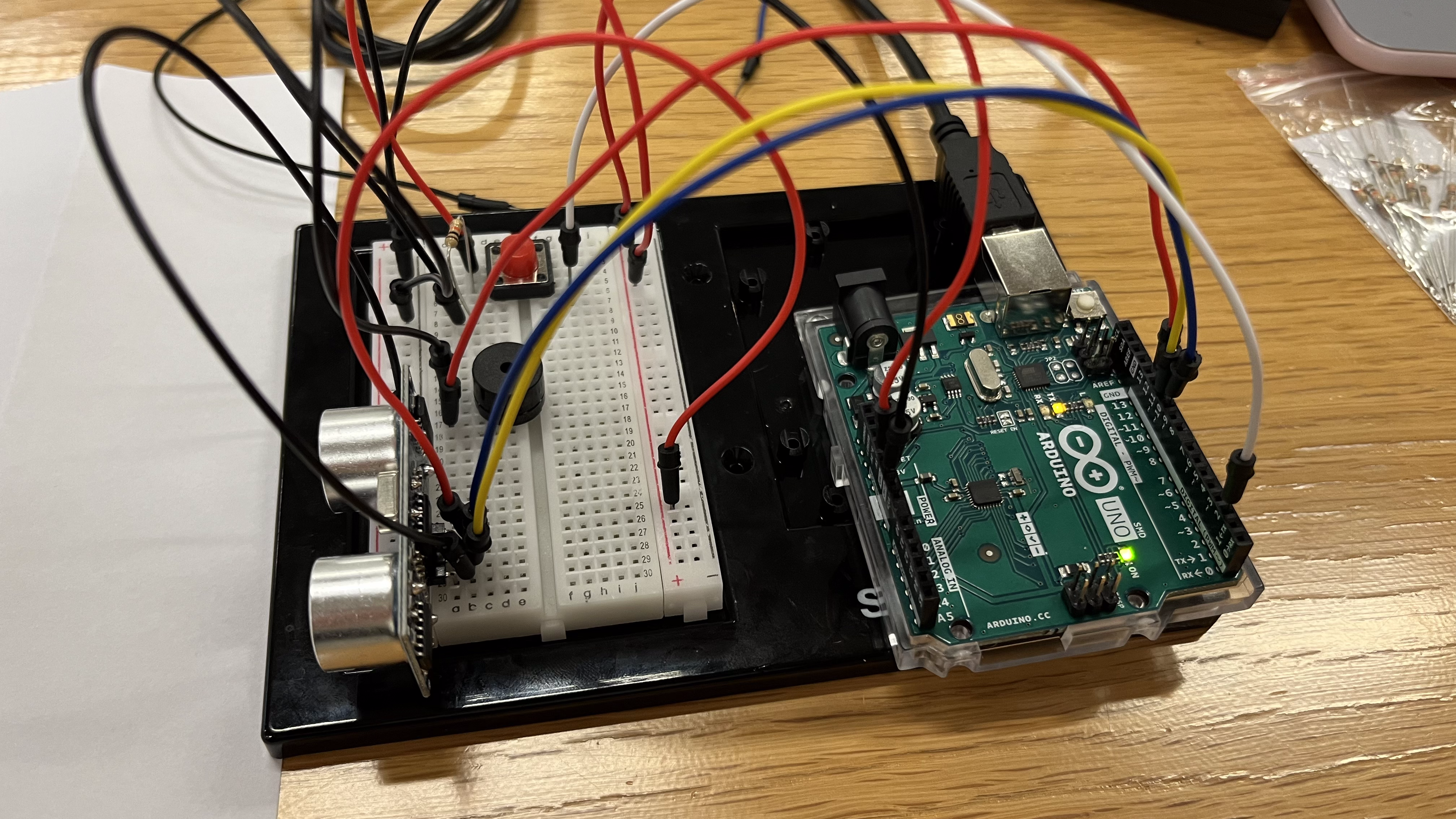
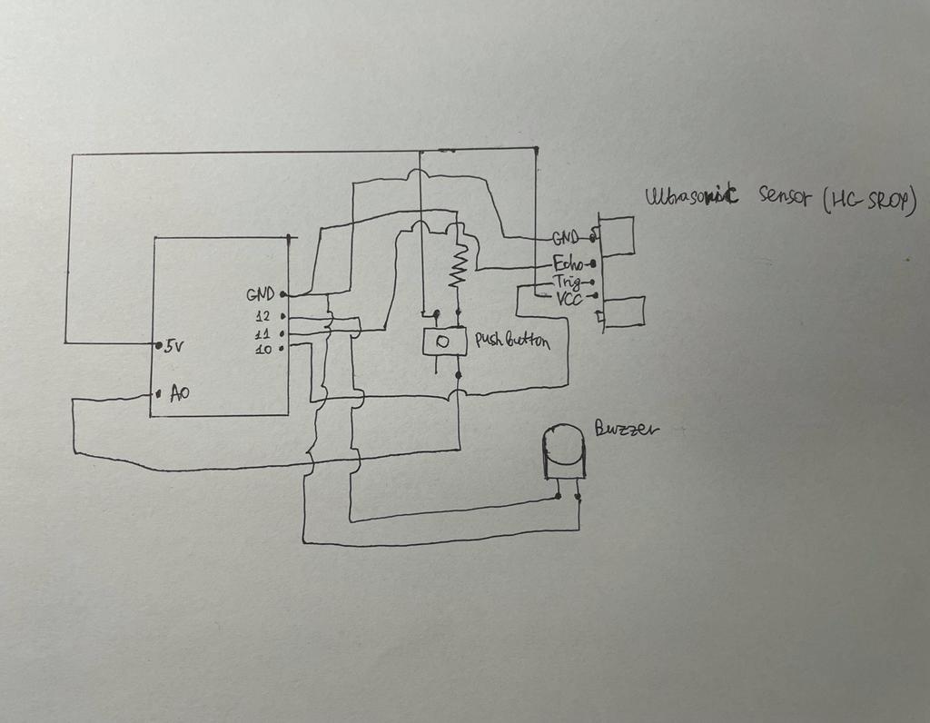
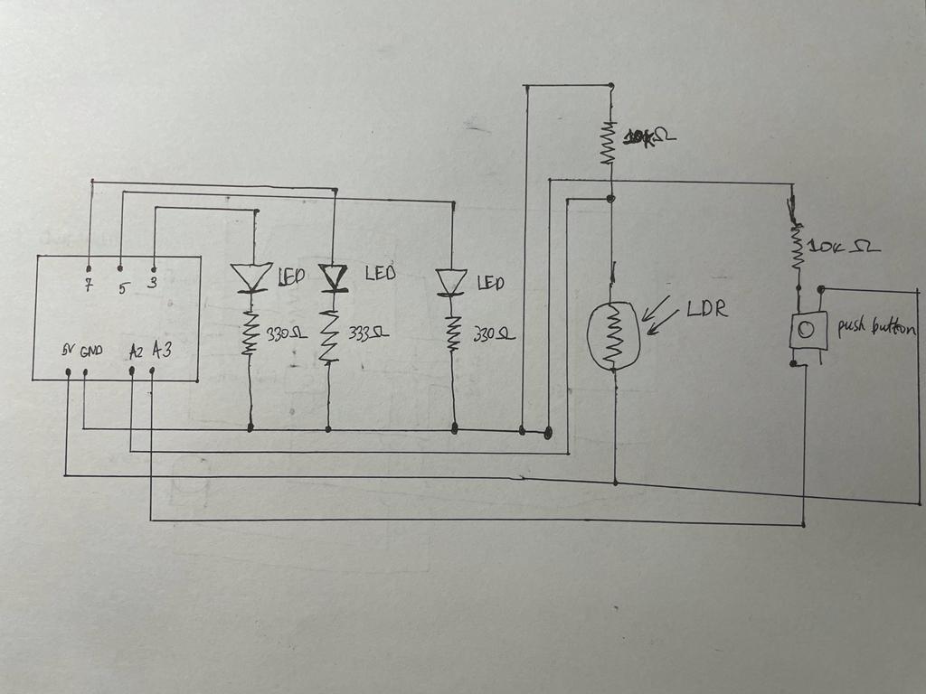
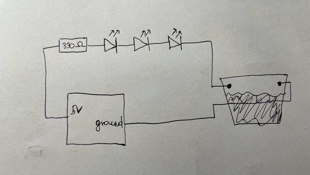
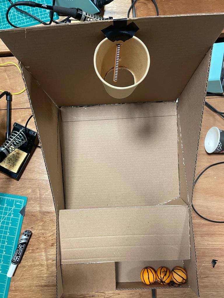
The Arduino program will read the sensor input to determine when the ball has been shot and passed through the hoop. The circuit will consist of a flex sensor and a resistor, with the flex sensor connected to an analog input on the Arduino board. The Arduino program will read the analog input to determine the current value of the flex sensor, which will change whenever a basketball passes through the hoop and contacts the sensor.
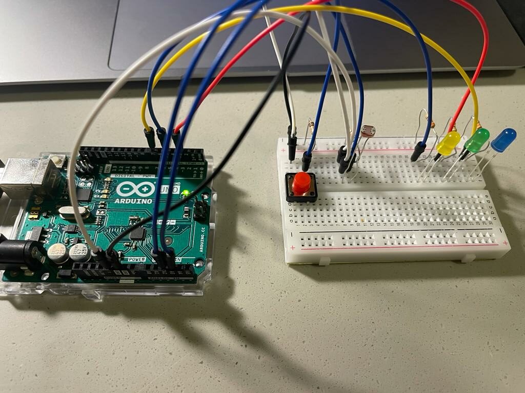
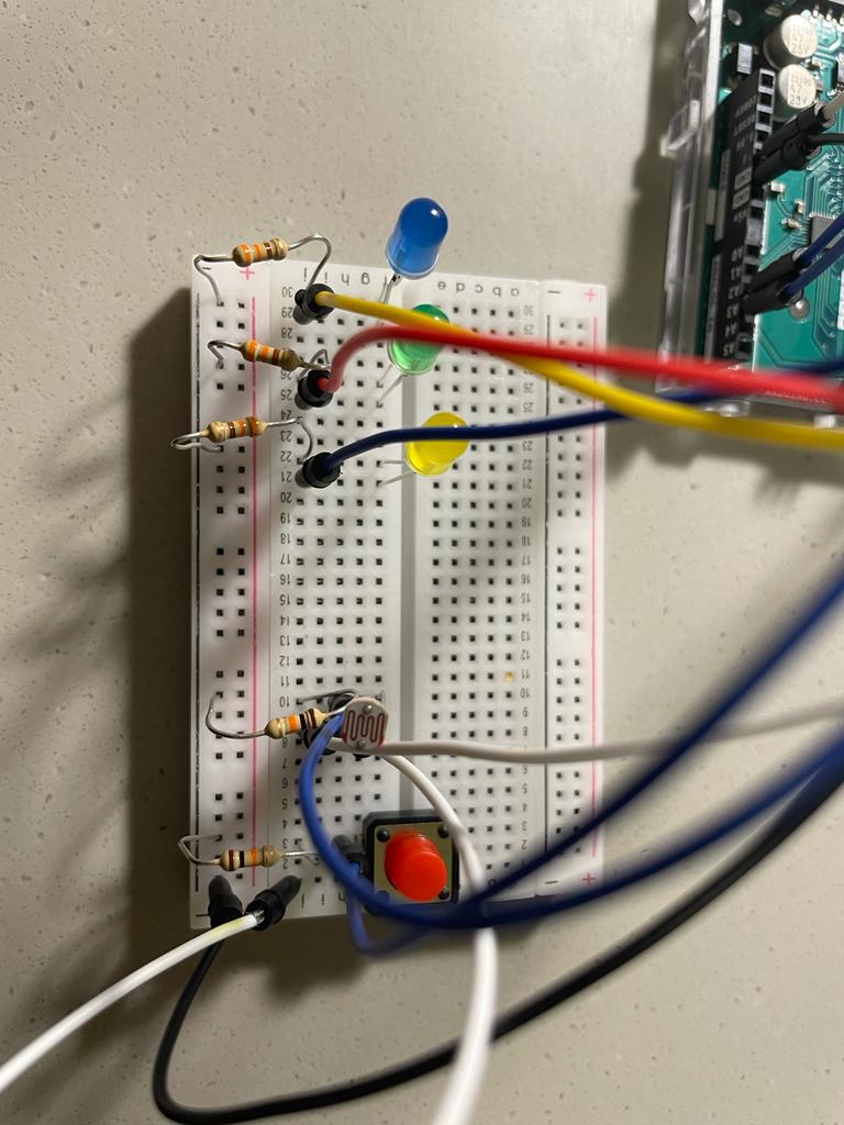
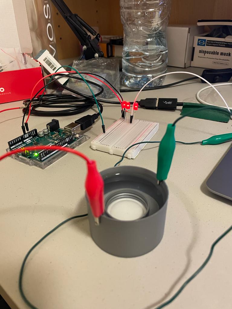
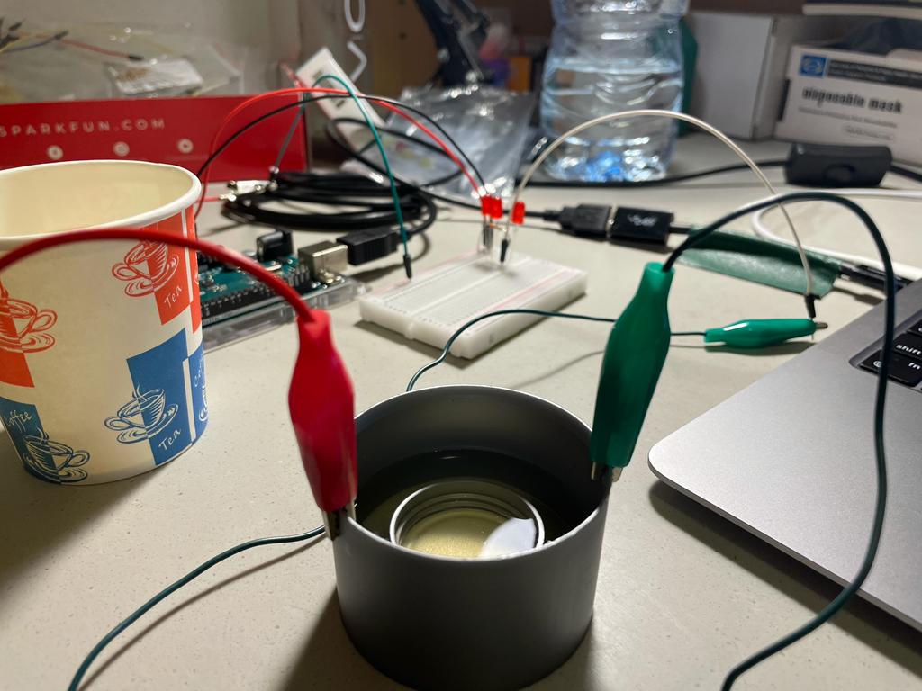
This Arduino code is designed to read analog input from a flex sensor connected to pin A0. In this case I built a sample circuit with LED to monitor if the flex sensor is working properly. The code begins by declaring constants for the LED pin (3) and the flex sensor pin (A0), and a variable to store the analog input value. In the setup function, the LED pin is set as an output pin, and serial communication is initialized at a baud rate of 9600.
The loop function continuously reads the analog value from the flex sensor using analogRead(), and then prints this value to the serial monitor using Serial.println(). The analog value is then mapped from the range 700-900 to the range 0-255 using the map() function. The resulting value is then used to control the brightness of the LED using analogWrite(), which sends a PWM signal to the LED pin. Finally, there is a small delay of 100ms before the loop starts again.
//Constants:
const int ledPin = 3;   //pin 3 has PWM funtion
const int flexPin = A0; //pin A0 to read analog input
//Variables:
int value; //save analog value
void setup(){

  pinMode(ledPin, OUTPUT);  //Set pin 3 as 'output'
  Serial.begin(9600);       //Begin serial communication
  while(Serial.available() <= 0) {
     Serial.println("0,0");
    }
}
void loop(){

  value = analogRead(flexPin);         //Read and save analog value
  Serial.println(value);               //Print value
  value = map(value, 700, 900, 0, 255);//Map value 0-1023 to 0-255 (PWM)
  analogWrite(ledPin, value);          //Send PWM value to led
  delay(100);                          //Small delay

}
Additionally, I tested photoresistor and infrared distance measurer as potential types of sensors for detecting when the basketball passes through the hoop. Based on my testing I determined that flex sensor is the most accurate and well-designed option.
COMMUNICATION BETWEEN ARDUINO/ P5.JS
The communication between Arduino and P5.js in the Mini Basketball Arcade Game is crucial for the game to function properly. The Arduino program reads the analog input from the flex sensor, which detects when the basketball passes through the hoop. Once the flex sensor value changes, the Arduino program sends this data to the P5.js program for processing and display on the scoreboard.
In order to establish communication between the two programs, the Arduino program uses the Serial communication protocol to send the sensor data to the P5.js program. The data is transmitted as a series of bytes that represent the flex sensor value. The P5.js program receives this data using the Serial communication library, which provides a way for the P5.js program to listen to the serial port and read the incoming data.
Once the P5.js program receives the flex sensor data from the Arduino program, it uses this data to update the score on the scoreboard. When data is received, the P5.js program reads the data and stores it in a variable. The P5.js program then uses this variable to update the player’s score based on the successful shots made by the player. The P5.js program also keeps track of the time remaining in the game and displays this information on the scoreboard.
What are some aspects of the project that you’re particularly proud of?
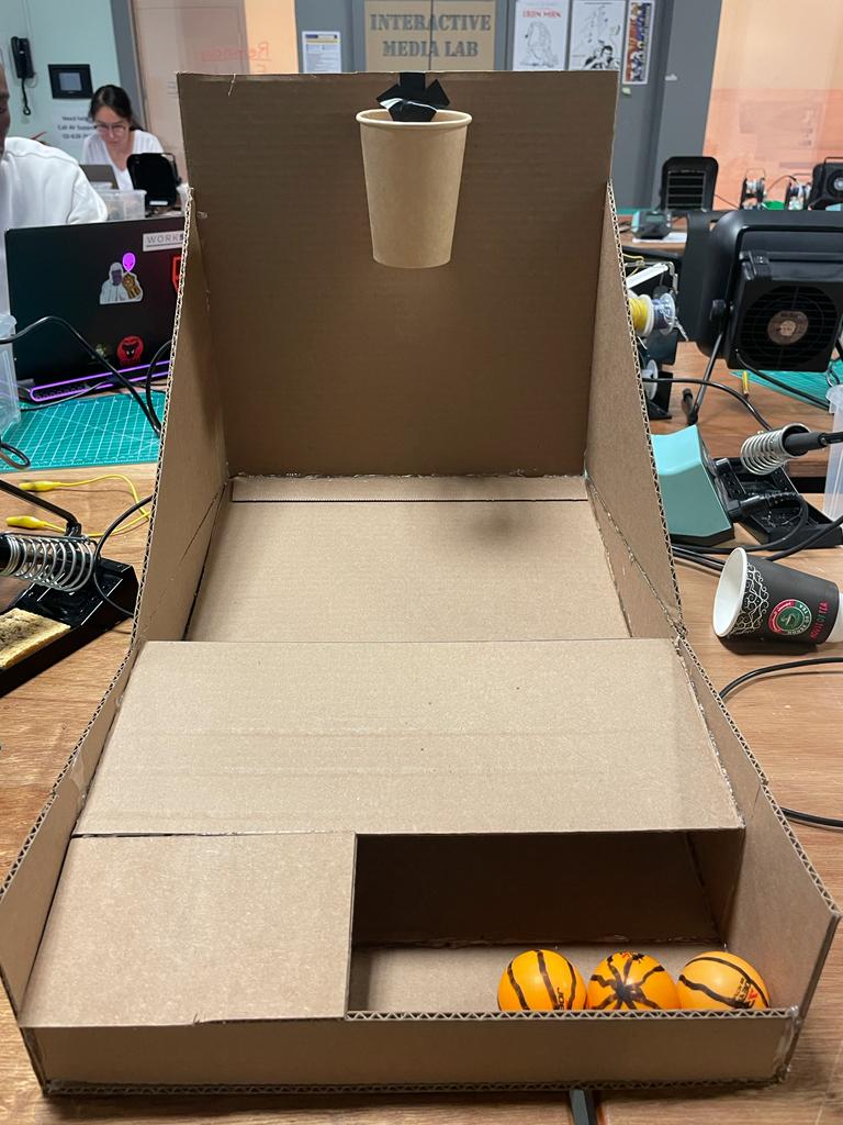
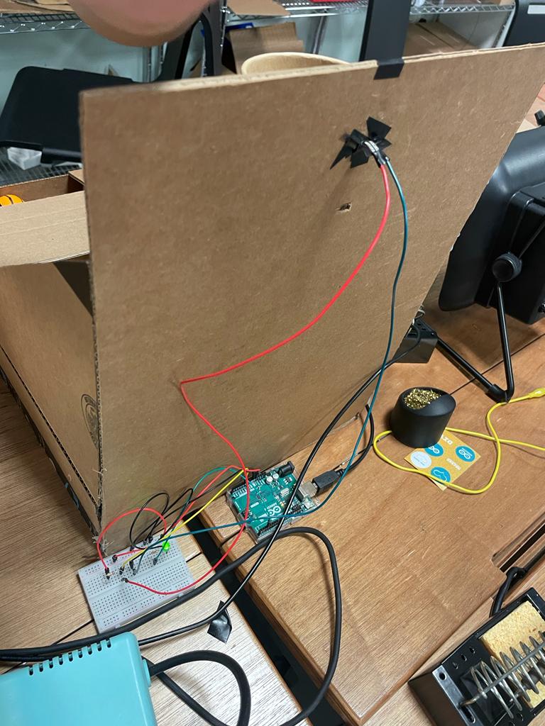
The main aspect I am very proud of in this project is the Mini Basketball Arcade Gaming Box that I created. I did not expect it to take so much time to build and design a game box, but I still enjoyed the process and came up with really user-friendly solution. I constructed a rectangular frame to support the basketball hoop, which also featured a ramp for the ball to return to the user, making it more convenient for the users to collect the balls after shooting. Following the initial user testing, I decided to enlarge the size of the frame, allowing more space for missed shots to fall onto the ramp and roll back to the user.
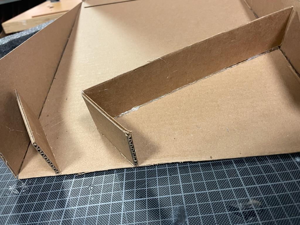
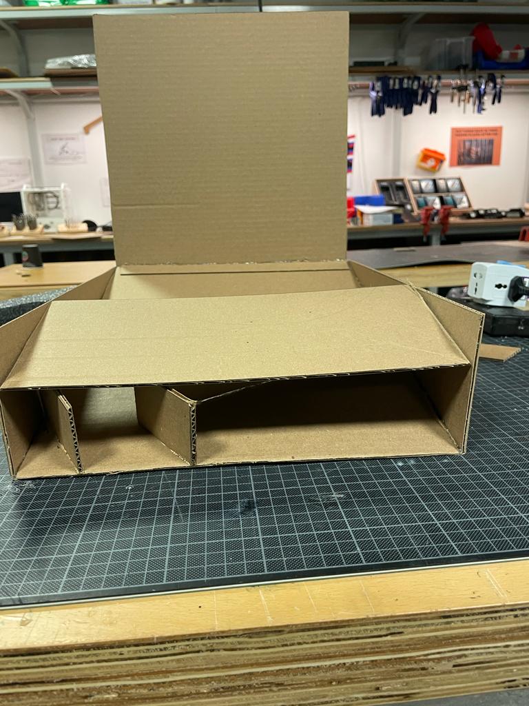
As you can observe from pictures above, I specifically created a path for the basketball to slide because in the first cases of user-testing I received a feedback about balls being stuck in the frame so I designed a path and additional section where used balls are stored.
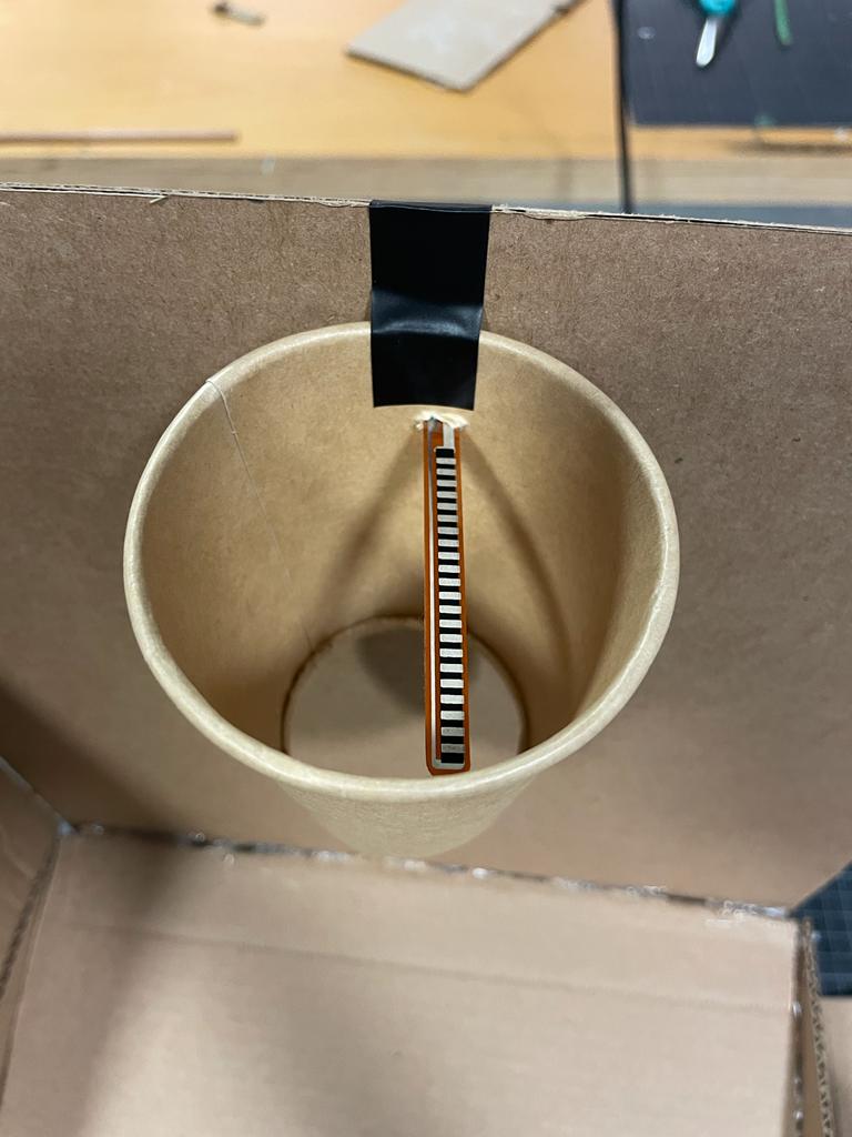
To create the hoop, I repurposed a paper coffee container, and the ball was a ping pong ball that I borrowed from the Fitness Center.
What are some areas for future improvement?
- One potential area is to improve the accuracy and precision of the flex sensor readings. The flex sensor used in the project is known to be sensitive to changes in temperature, humidity, and other environmental factors. Also the right positioning of the flex sensor is crucial because it needs to be centered so that it would 100% detect the falling ball. Because I used tennis balls the attachment to the hoop also caused substantial issues resulting in faulty detections.
- Another potential game level could involve increasing the difficulty of the shots required to score points. For example, the basket could be moved to different locations or the size of the basket could be decreased. To implement this, the code would need to randomly generate new positions for the basket and adjust the size of the basket accordingly. The code would also need to calculate the trajectory of the ball and determine whether it goes through the basket.
User Testing
For the final user testing, I asked Aaron and Symbat to test my game without giving them any prompts/instructions . User testing was important to identifying what to work on in my project.
Are they able to figure it out? Where do they get confused and why? Do they understand the mapping between the controls and what happens in the experience?
It was very straightforward because I made the design of the game box and even tennis balls obviously basketball themed and there was not any confusion in figuring out the interaction design. They both immediately understood how to play the game and the mapping between the controls and what happens in the experience. Physical act of shooting a miniature basketball into the hoop, which is the primary user input was well implemented and tested.
What parts of the experience are working well? What areas could be improved?
The whole interaction design part is working surprisingly well. P5.js program offers an interactive and immersive basketball game, featuring a visually appealing interface with a scoreboard showing the current score and time remaining. Users can shoot basketballs through the hoop, and the program responds with feedback sounds and updates the score. The game also includes a time limit, adding an extra layer of excitement and challenge. A buzzer sounds when the time runs out, and the user can view their final score and compare it with the highest score achieved.
As mentioned before, one potential area is to improve the accuracy and precision of the flex sensor readings because sometimes when the flex sensor is tilted from its position it might count faulty results. Additionally, because I am using very light tennis ball it compromises the best positioning of sensor by getting a bit heavier ball of same size the accuracy would be perfect.
What parts of your project did you feel the need to explain? How could you make these areas more clear to someone that is experiencing your project for the first time?
I received some questions about how the shoots are detected and what sensors I used. I could provide more information about the different types of sensors being tested (photoresistor and infrared distance measurer) and how they work. This would help the user understand the reasoning behind using a flex sensor and how it compares to other potential sensor options. I can also explain about the materials and components required to build the physical arcade machine. This would give the user a better understanding of the physical aspects of the project and how they fit together.