Introduction
Our task in this report is to get information from at least one analog sensor and at least one digital sensor (switch), and use this information to control at least two LEDs, one in a digital fashion and the other in an analog fashion, in some creative way.
I will use the Arduino prototyping board for the digital and analog input and output for the interaction.
For the digital input I will use a push button.
For the digital output a LED is used.
For the analog input a sound sensor is used.
For the analog LED output an RGB LED is used.
Challenged Faced
The first challenge faced is to identify the needed input and output devices.
After researching the available simple devices, I decided on using buttons, sound sensor, LED and RGB LED.
The pins used for digital are the integer pins in the Arduino. The analog pins are pin A0 to A5 on the Arduino.
The second challenge was to do the circuit and connection required. I used tutorials from Arduino forums in order to connect the circuit.
The third challenge was to code the Arduino , using the Arduino IDE I wrote a code in C to program the Arduino.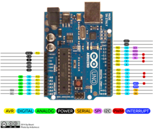
Video:
Procedure
Step 1 : Button with LED output
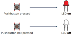
Digital input controlling a digital input button.
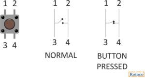
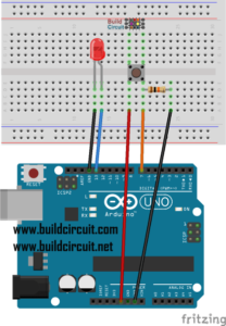
Connecting the button:
The button is connected to pin 7 through a resistor of 1 kohm.
Step 2 : LED Digital
The connection of the LED is to the digital pin 13.
Code for connecting the button and the led:
int ledPin = 13; // The LED is connected to pin 13
int button = 7; // The button is connected to pin 7
int val = 0;
void setup () {
   pinMode (ledPin, OUTPUT); // The LED pin is an output
   pinMode (button, INPUT); // The pin of the button is an entry
   }
void loop () {

   val = digitalRead (button); // Reading the button

   if (val == 1) {// If the value of the button is 1
     digitalWrite (ledPin, HIGH); // Turn on the LED
   }
   else {// Otherwise:
     digitalWrite (ledPin, LOW); // Turn off the LED
   }
}
Step 3 : Input analog
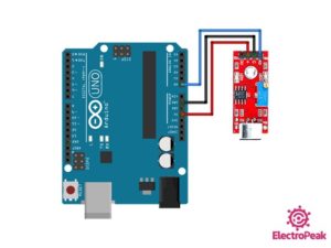
The analog input I are using is a sound sensor KY-037
It is connected to A0 analog pin on Arduino.
Step 4: Analog output
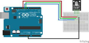
As analog output I will use the 4 pin RGB LED.
In order to make it easier to connect it, I will use a module of RGB light: KY-016 RGB FULL COLOR LED MODULE.
The module is an RGB 4 pin LED connected to 3 resistor each of 150ohm to protect the pins.
This module uses PWM in order to send analog signals to the LED to turn on in different colors.
The connection is done as per the table below:
| Pins | Arduino Pin |
| R | Pin 11 |
| B | Pin 10 |
| G | Pin 9 |
| GND | GND |
The code to control the RGB light is first to write in the setup:
pinMode(redpin, OUTPUT);
  pinMode(bluepin, OUTPUT);
  pinMode(greenpin, OUTPUT);
  Serial.begin(9600);
Then I need to add in the function setcolor:
void setColor(int red, int green, int blue)
{
  //use PWM to controlt the brightness of the RGB LED
  analogWrite(redPin, red);
  analogWrite(greenPin, green);
  analogWrite(bluePin, blue);
}
Now I can use the setcolor function in the Arduino loop code to change the color depending on different functions.
I programmed it depending on the sound of the sensor:
sound lower than 25 : no color
sound between 25 and 30 : yellow color
sound higher than 30 : red color
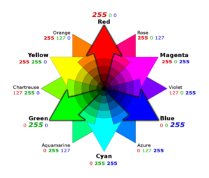
Using the code for colors:
setColor(255, 0, 0);  // red
setColor(0, 255, 0);  // green
setColor(255, 255, 0);  // yellow
Final Outcome:
The circuit is built now and all inputs and outputs are working.
In order to give it a mission, I designed the code as the following:
SQUID GAME green and red light
Rule of the game: the player should press the button when the red light is on
Winner: blue lights turns on
When squid game starts, the sound sensor detects it and start a sequence:
-Green light is on
-Green is off and Red light is on for a short time: in this time the player should press the button
-if the player pressed the button while the red light was on, he will win
-if the player wins both lights will be blue indicating a win
-if the player doesn’t press in time, no blue light is on, so he lost.
Rule of the game: the player should press the button when the red light is on
Winner: blue lights turns on
Song for quid game: https://www.youtube.com/watch?v=9jcHItQvKIQ
Conclusion
As I completed this project I learned about different inputs and outputs and how the Arduino could be used to have different applications.
Squid Game Code
int ledPin = 13; // The LED is connected to pin 13
int button = 7; // The button is connected to pin 7
int val = 0;
int redpin =11;
int bluepin=10;
int greenpin=9;

void setup () {
   pinMode (ledPin, OUTPUT); // The LED pin is an output
   pinMode (button, INPUT); // The pin of the button is an entry
   pinMode(redpin, OUTPUT);
  pinMode(bluepin, OUTPUT);
  pinMode(greenpin, OUTPUT);
  Serial.begin(9600);
setColor(0, 0, 0);
   }
void loop () {

   int sound = analogRead(A0);

Serial.print(sound); Serial.println(" Sound");

//if (sound<40) setColor(, 0, 0);//green
//else if (sound<42) setColor(255, 255, 0);  //yellow
//else if (sound>42) setColor(255, 0, 0);  //red
if (sound>42)
{ setColor(255, 255, 0);
delay(5000);
setColor(255, 0, 0);
delay(2000);
val = digitalRead (button); // Reading the button

   if (val == 1) {// If the value of the button is 1
     digitalWrite (ledPin, HIGH); // Turn on the LED
     setColor(0, 0, 255);
     delay(2000);
     digitalWrite (ledPin, LOW);
   }
   else {// Otherwise:
     digitalWrite (ledPin, LOW); // Turn off the LED
     delay(2000);
   }}

else setColor(0, 0, 0);

}
void setColor(int red, int green, int blue)
{
  //use PWM to controlt the brightness of the RGB LED
  analogWrite(redpin, red);
  analogWrite(greenpin, green);
  analogWrite(bluepin, blue);
}

