
Concept & Inspiration
For this assignment, my aim was to create a simple gamified experience that engaged the user. I used to play this intuition game with my sister where she would think of a random number and I would try to “read” her mind and guess what that number was. With context clues of how “warm” or “cold” my guess was, I would eventually be able to get to the correct answer. My circuit is effectively a realization of this in hardware form.
Implementation
The circuit is composed of one RGB LED, three LEDs, a potentiometer, and a momentary switch. The game starts with the user pressing on the momentary switch (the digital sensor), upon which the Arduino program initializes a random number to be guessed. Upon activating the circuit, the RGB LED lights up in a pink color, indicating that the game is underway. The user then has to guess the number by using the potentiometer (the analog sensor) to find the correct value. The blue LED is lit if the current guess is far away from the correct number. The red LED lights up if the user is within a close range of the answer (±100 in my implementation). Once the number is guessed, the green LED lights up and the game is won. If the game is won, the RGB LED light show starts to celebrate the win, with different colors illuminating in succession. The user can turn off all the LEDs and restart the game using the momentary switch.
Code Snippets
The function setColor controls the color of the RGB LED in an analog fashion. This function is called when the game is started using the switch to set the color of the RGB LED to pink, and when the game is won, transitioning the RGB LED from having a static color to a dynamic light show (implementation below). The principle of blinking without delay is used to ensure the RGB LED seamlessly transitions from one color to the next and that the user is able to turn off all the lights without lags using the momentary switch.
void setColor(int redValue, int greenValue, int blueValue) {
  analogWrite(redRGBPin, redValue);
  analogWrite(greenRGBPin, greenValue);
  analogWrite(blueRGBPin, blueValue);
}
if (won && gameState){
  if (millis()>timer){
    timer = millis()+interval;
    i = (i+1)%5;
  }
  if (i == 0){
    setColor(255, 0, 0); // red
  }
  else if (i==1){
    setColor(0, 255, 0); // green
  }
  else if (i==2){
    setColor(0, 0, 255); // blue
  }
  else if (i==3){
    setColor(255, 255, 255); // white
  }
  else if (i==4){
    setColor(170, 0, 255); // purple
  }
}
The game logic occurs inside the loop function, where the potentiometer value is read and compared against the number to be guessed. The potentiometer controls which LED lights up based on its value’s distance from the correct number (blue if the guess is far away from the correct answer, red if the guess is close, and green if it is correct).
if (gameState && !won){
    setColor(227,50,121); // pink
    if (abs(pentSensorVal - randNum) == 0){ // if number is guessed correctly
      digitalWrite(greenPin, HIGH);
      digitalWrite(bluePin, LOW);
      digitalWrite(redPin, LOW);
      won = true;
    }
    else if (abs(pentSensorVal - randNum) < 100){ // getting warmer
      digitalWrite(greenPin, LOW);
      digitalWrite(bluePin, LOW);
      digitalWrite(redPin, HIGH);
    }
    else{ // you are way off
      digitalWrite(greenPin, LOW);
      digitalWrite(bluePin, HIGH);
      digitalWrite(redPin, LOW);
    }
  }
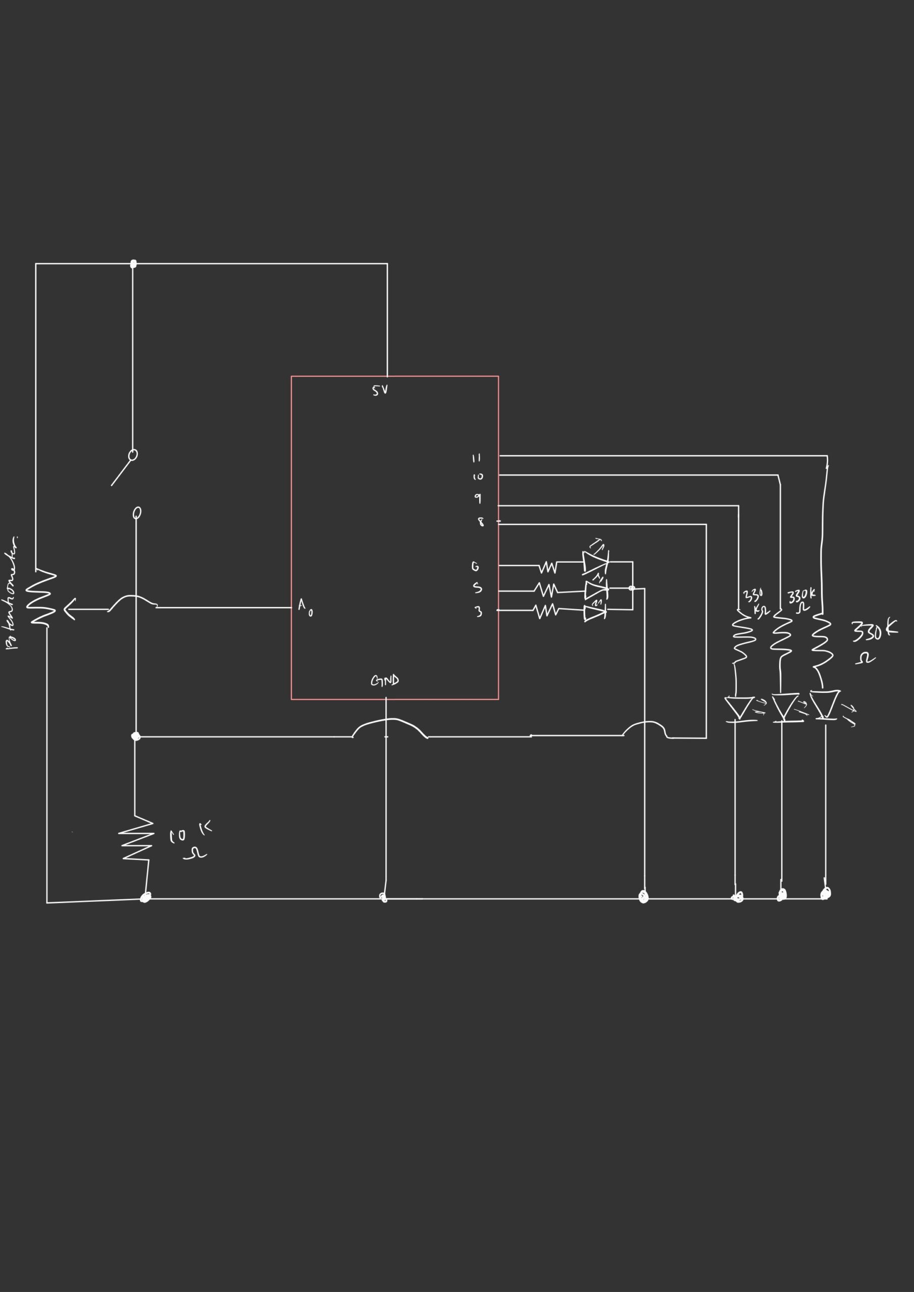
Circuit Schematic
Here’s the schematic of the wiring of the hardware components:
Demo
Reflections and Extensions
After last week’s reading, I wanted to focus more on the creative idea than the technical complexity of the hardware components. It proved to be quite challenging to think of building something creative with the input sensors and output devices that we have been using in class. I spent a lot of time ideating and the implementation portion was not as time-consuming, especially since I made sure to diagram the schematic and outline the software logic prior to wiring the circuit and connecting the Arduino. One thing that I should have anticipated, however, is how easy the game would be due to the limited directionality of the potentiometer. If you know that your guess is not correct by dialing the potentiometer all the way to the left, for example, the answer must be found by dialing it all the way to the right. To make the game a little harder, I made the trivial modification of adding a second potentiometer. The guess is considered correct if the sum of the potentiometer readings is within 50 of the number to be guessed. I increased the “warm” range from ±100 to ±500 as it was getting extremely difficult to play the game.
sum = pentSensorVal1 + pentSensorVal2;
if (abs(sum - randNum) < 50){
  digitalWrite(greenPin, HIGH);
  digitalWrite(bluePin, LOW);
  digitalWrite(redPin, LOW);
  won = true;
}
else if (abs(sum - randNum) < 500){
  digitalWrite(greenPin, LOW);
  digitalWrite(bluePin, LOW);
  digitalWrite(redPin, HIGH);
}
else{
  digitalWrite(greenPin, LOW);
  digitalWrite(bluePin, HIGH);
  digitalWrite(redPin, LOW);
}
Admittedly, adding a second analog sensor introduced complexity that came at the expense of interpretability. It becomes harder to strategize one’s guesses, partly due to the nature of the potentiometer values being hard to track. Perhaps using a display, like an LCD, to reveal the current potentiometer values would be helpful.