Concept
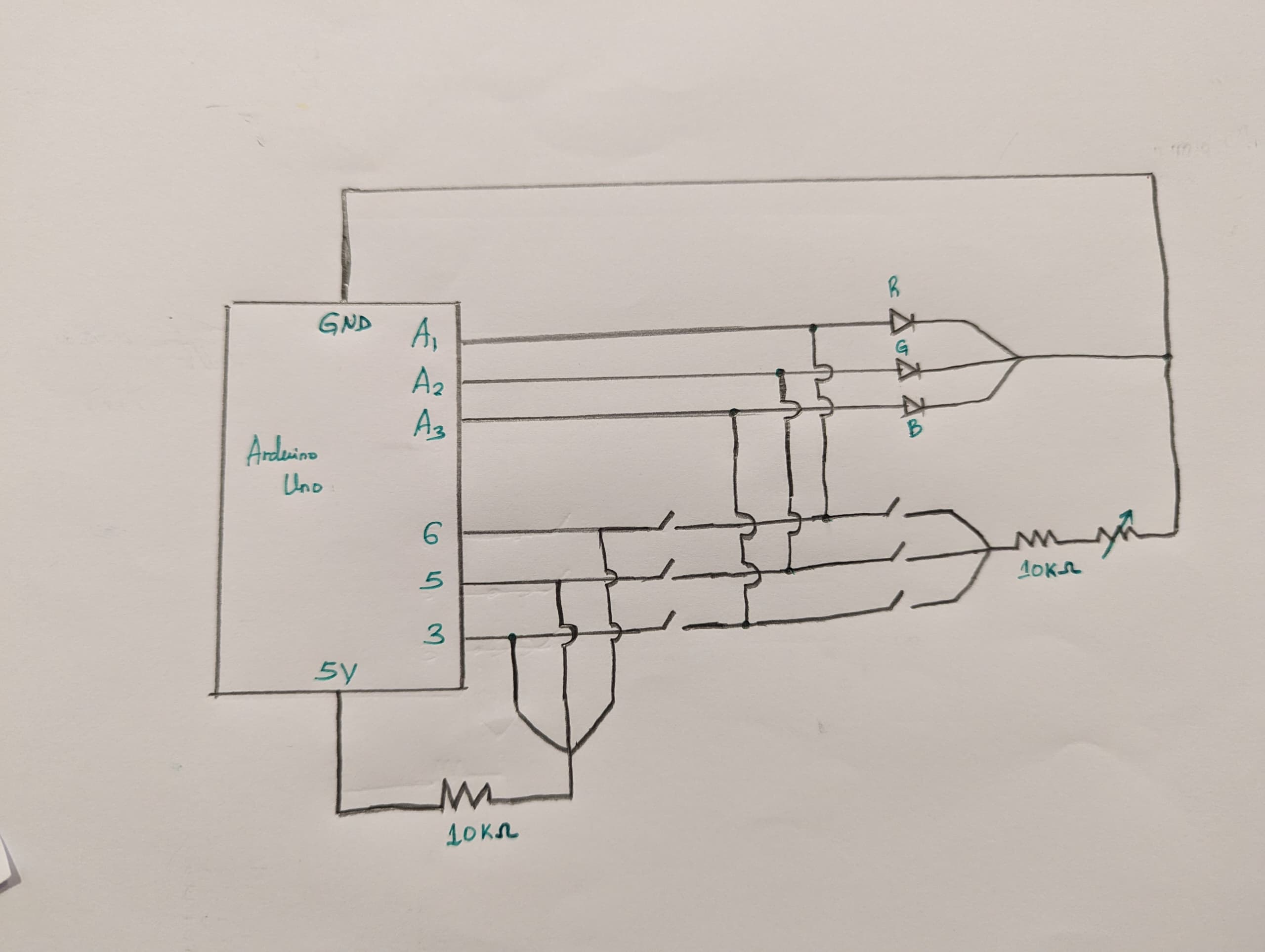
This week, I created a simple switch to control the lights of LEDs both digitally and in an analog way. For the digital control, I used basic switches, and for the analog control, I used a potentiometer. The potentiometer detects and measures the voltage based on how much the knob or slider is turned.
Schematic Diagram
Code
// Pin definitions for the RGB LED
const int redPin = 6;
const int greenPin = 5;
const int bluePin = 3;
// Analog input pins for potentiometers
const int redControl = A1;
const int greenControl = A2;
const int blueControl = A3;
void setup() {
// Set RGB LED pins as outputs
pinMode(redPin, OUTPUT);
pinMode(greenPin, OUTPUT);
pinMode(bluePin, OUTPUT);
// Initialize serial communication for debugging
Serial.begin(9600);
}
void loop() {
// Read values from potentiometers (0-1023 range)
int redValue = analogRead(redControl);
int greenValue = analogRead(greenControl);
int blueValue = analogRead(blueControl);
// Map potentiometer values to PWM range (0-255)
int redBrightness = map(redValue, 0, 1023, 0, 255);
int greenBrightness = map(greenValue, 0, 1023, 0, 255);
int blueBrightness = map(blueValue, 0, 1023, 0, 255);
// Set the brightness of each color channel
analogWrite(redPin, redBrightness);
analogWrite(greenPin, greenBrightness);
analogWrite(bluePin, blueBrightness);
// Print the brightness values to the Serial Monitor
Serial.print("Red: ");
Serial.print(redBrightness);
Serial.print("\tGreen: ");
Serial.print(greenBrightness);
Serial.print("\tBlue: ");
Serial.println(blueBrightness);
// Short delay to make output more readable
delay(100);
}
// Pin definitions for the RGB LED const int redPin = 6; const int greenPin = 5; const int bluePin = 3; // Analog input pins for potentiometers const int redControl = A1; const int greenControl = A2; const int blueControl = A3; void setup() { // Set RGB LED pins as outputs pinMode(redPin, OUTPUT); pinMode(greenPin, OUTPUT); pinMode(bluePin, OUTPUT); // Initialize serial communication for debugging Serial.begin(9600); } void loop() { // Read values from potentiometers (0-1023 range) int redValue = analogRead(redControl); int greenValue = analogRead(greenControl); int blueValue = analogRead(blueControl); // Map potentiometer values to PWM range (0-255) int redBrightness = map(redValue, 0, 1023, 0, 255); int greenBrightness = map(greenValue, 0, 1023, 0, 255); int blueBrightness = map(blueValue, 0, 1023, 0, 255); // Set the brightness of each color channel analogWrite(redPin, redBrightness); analogWrite(greenPin, greenBrightness); analogWrite(bluePin, blueBrightness); // Print the brightness values to the Serial Monitor Serial.print("Red: "); Serial.print(redBrightness); Serial.print("\tGreen: "); Serial.print(greenBrightness); Serial.print("\tBlue: "); Serial.println(blueBrightness); // Short delay to make output more readable delay(100); }
Video Demonstration of my design can be seen below:
Reflection for future works
I am proud of the progress I made in designing and implementing the analog and digital switch controls for the LEDs. This simple project has greatly enhanced my understanding of how these systems work. I look forward to taking on more challenging tasks, particularly those that involve further manipulation of analog signals.